cc/td/doc/product/access/sc/rel7/soln/das22
hometocprevnextglossaryfeedbacksearchhelp
PDF

Table Of Contents

Cisco SS7 Interconnect for Access Servers Solution Introduction

Overview

Cisco Signaling Controller Product Information

Understanding Terminology

Architecture

Benefits

Features

Scalability and Performance

System Redundancy

Cisco Signaling Controller Management

Network Access Server Management

Cisco Signaling Link Terminal Management

Cisco Media Gateway Controller Node Manager

Cisco Gateway Control Protocol Design

Cisco SS7 Interconnect for Access Servers Solution Introduction


Overview

The Cisco SS7 Interconnect for Access Servers Solution is a distributed system that interconnects Cisco network access servers (NASs) to a circuit-switched TDM network using the Signaling System 7 (SS7) protocol. The interconnections are achieved using a protocol conversion platform called the Cisco SC2200 combined with the Cisco Signaling Link Terminal (SLT). The Cisco SC2200 consists of a hardware and software package that provides the signaling controller function in the Cisco SS7 Interconnect for Access Servers Solution. It provides high availability, high performance, and key scaling.

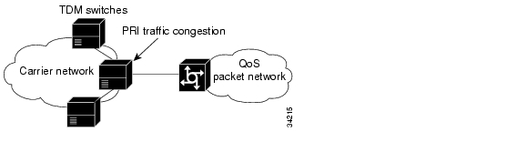
When large points of presence (POPs) receive calls from the Public Switched Telephone Network (PSTN), the traffic runs over legacy architectures that use in-band signaling (such as Integrated Services Digital Network Primary Rate Interfaces (ISDN PRIs), in-band channel-associated signaling (CAS), or single analog lines) rather than out-of-band signaling like SS7. With both signaling and bearer traffic running over the lines, these legacy switches become congested with modem traffic and limited circuits. Cisco offers the Cisco SS7 Interconnect for Access Servers Solution that offloads the signaling to an out-of-band network so that available bandwidth increases.

The Cisco SS7 Interconnect for Access Servers Solution is a distributed system that adds SS7 signaling interfaces to large ISP POPs. SS7 interfaces are connected to the PSTN by using the same signaling technology as a PSTN switch. The Cisco SS7 Interconnect for Access Servers Solution consists of the Cisco SC2200, the Cisco SLT, and the NASs. The Cisco SS7 Interconnect for Access Servers Solution turns a POP into an end-office switching system in the PSTN, allowing direct peer-to-peer signaling connectivity. The POP, as a switch, connects directly to the rest of the network as a peer. After connections to the Internet are aggregated at a POP, streams of user packets are statistically multiplexed for efficient transport over the backbone network.

Figure 1-1 illustrates the PSTN-to-POP network without a Cisco SS7 Interconnect for Access Servers Solution. Because of Internet and additional data calls with hold times that average 30 minutes, the PSTN network experiences more busy signals and overloads network resources.

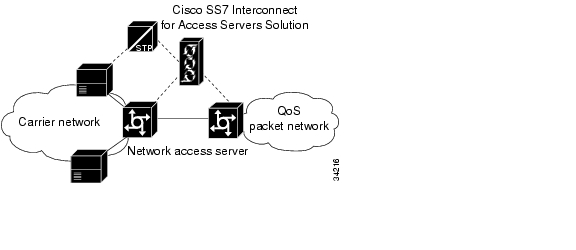
Quality of Service (QoS) packet network in both Figure 1-1 and Figure 1-2 refers to a packet network in which both bandwidth control and latency control are achieved for the particular application.

Figure 1-1 Without the Cisco SS7 Interconnect for Access Servers Solution

Figure 1-2 illustrates where the Cisco SS7 Interconnect for Access Servers Solution is located when it is dropped into a PSTN to offload calls. Note that the NASs are connected with a Cisco SC2200. By placing the Cisco SS7 Interconnect for Access Servers Solution as close to the ingress switch as possible, data traffic ties up fewer PSTN resources. The direct connection of the Cisco SS7 Interconnect for Access Servers Solution to the SS7 network provides advantages such as faster call setups and teardowns, as well as SS7's look-ahead capabilities for rerouting to avoid downed network nodes and links.

Figure 1-2 With the Cisco SS7 Interconnect for Access Servers Solution

Cisco Signaling Controller Product Information

The Cisco SC2200 is a signaling controller (SC) that converts telephony signals from one format to another. For example, the Cisco SC2200 converts SS7 signaling information from the PSTN to the signaling format required to establish calls between the PSTN and a packet data network.

The Cisco SC2200 is part of the Cisco Media Gateway Controller (MGC) product line. The Cisco MGC product line consists of hardware and software packages that you can use to connect your packet data network to the PSTN. Cisco MGC products manage call signaling conversion between the PSTN and the packet data network, and depending on the product, Cisco MGC products can control the routing of calls across the PSTN or packet data network.


Note Your Cisco SS7 Interconnect for Access Servers Solution documentation suite includes Cisco MGC reference books.


Note Some product labels and packaging might use the term telephony controller. Any references to the telephony controller apply to the Cisco MGC.


Understanding Terminology

The following key terms are used in this document to describe the Cisco SS7 Interconnect for Access Servers Solution architecture:

Cisco SC2200—A hardware and software package that provides the signaling controller function. Typically this includes two SC hosts in a redundant configuration for continuous-service.

SC host—A Sun host that runs signaling controller software.

SC node—The combination of hardware (Sun servers and Cisco SLTs) and software that provides the signaling controller function and transports the signaling traffic between the SC hosts and the SS7 signaling network.

SC zone—The combination of an SC node and the Cisco NASs that are provided with signaling services.

Architecture

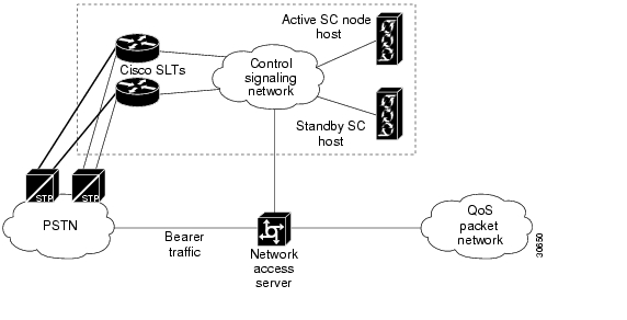
The architecture of the Cisco SS7 Interconnect for Access Servers Solution, shown in Figure 1-3, enables a NAS to operate in an environment where SS7 is used to establish calls on the bearer channels connected to the NAS.

Table 1-1 lists the components required by the Cisco SS7 Interconnect for Access Servers Solution. These components are described in greater detail in the "Cisco SS7 Interconnect for Access Servers Solution Components" section.

Table 1-1 Components for the Cisco SS7 Interconnect for Access Servers Solution

Component
Description

Cisco Signaling Controller Host (Cisco SC2200)

At MTP3 and higher layers, operates as an SS7 to ISDN protocol converter front-end to the NASs.

Cisco Signaling Link Terminal (Cisco SLT)

Used for physical SS7 link termination and MTP1 and MTP2 termination.


Note The Cisco SLT is designed to be colocated with the Cisco SC2200 and interconnected with a local area IP network. Remote connectivity between the Cisco SLT and the Cisco SC2200 is currently not supported.


Cisco Network Access Server (Cisco AS5200, Cisco AS5300, Cisco AS5350, Cisco AS5400, and Cisco AS5800)

Used for data ISDN User Part (ISUP) trunk termination.


Note The Cisco AS5200 can no longer be ordered. Cisco supports the existing installation base only.


LAN Switch (Cisco Catalyst Switch Family)

Provides infrastructure for the redundant and reliable Cisco SC2200 architecture. Connects multiple Cisco SLTs to the active and standby hosts within the Cisco SC2200 node. Connects the NASs with their controlling Cisco SC2200 node. Connects the originating Cisco SC2200 zone to the terminating Cisco SC2200 node between Cisco SC2200 zones.


Note The switch is customer premises equipment and is not provided with the Cisco SC2200.


Cisco Media Gateway Controller Node Manager (CMNM)

Integrates the management interfaces and management functionality of the Cisco MGC node components into a comprehensive human interface and data repository.


Note CMNM is available with Release 2.2 of the Cisco SS7 Interconnect for Access Servers Solution.


Figure 1-3 Cisco SS7 Interconnect for Access Servers Architecture

Benefits

Using the Cisco SS7 Interconnect for Access Servers Solution provides the following benefits:

Provides wholesale dial services, dialup Virtual Private Networks (VPNs), Internet access, and voice services, while interconnecting as a carrier.

Addresses voice network congestion by using the SS7 interfaces to make features such as rerouting on overflow conditions and the use of Intelligent Network (IN) functions possible, which further drives down operating costs.

Replaces ISDN PRIs with bearer trunks and separates the signaling to increase bandwidth.

Installs an SS7 POP in a new location without the added expense of a switch.

Integrates the NASs directly into the SS7 network, using the Cisco SS7 Interconnect for Access Servers Solution and thus removes the need for two switch ports on the PSTN circuit switch for each NAS port installed.

Increases the signaling channel to bearer channel ratios, thus decreasing the number of signaling channels needed and the overall complexity of the system or network.

Provides economical reliability of SS7 link termination by using channelized E1/T1 software on the Cisco SLT.

Transparently passes individual and uncompressed T1 or E1 channels between T1 or E1 ports by using Drop and Insert interfaces.

Features

Table 1-2 briefly lists features that are provided with your Cisco SS7 Interconnect for Access Servers Solution. For an overview of scalability and performance, system redundancy, management, and software requirements, see subsequent sections of this document. For the most up-to-date list of the supported telephony protocols, refer to the Release Notes for Cisco Media Gateway Controller Software Release 7.

Table 1-2 Features for the Cisco SS7 Interconnect for Access Servers Solution 

Feature
Purpose

Directly connects access servers to PSTN in a peer-to-peer interconnect

Reduces network costs.

Interconnects with more favorable tariffs and rates.

Intelligent Network (IN) triggers

TCAP over IP.

TCAP local number portability (LNP) support.

800/900 number translation.

Provides a reliable IP link between signaling controllers and NASs with Redundant Link Manager (RLM)

No single point of failure in connection between NAS and signaling controller.

Dial outsourcing

The Cisco SC2200 and NASs can be provisioned by telephone service providers and local exchange carriers. Calls can be directed to NASs belonging to various ISPs.

Facility-associated signaling provided by the Cisco SLTs

Grooms off the bearer channels and then delivers them to the NASs.

Delivers MTP-3 to the signaling controller over Reliable User Data Protocol (RUDP).

Resource management

Shares modems across POPs among various wholesale customers.

Single point of management.

Introduces services such as wholesale dial, Virtual Private Dial-up Networks (VPDNs), and virtual modem pooling

Realizes new revenues.

Reduces PSTN congestion.

Supports colocated and distributed access servers

Cost savings; scalable and flexible.

Supports Cisco AS5200, Cisco AS5300, Cisco AS5350, Cisco 5400, and Cisco AS5800

Note The Cisco AS5200 can no longer be ordered. Cisco supports the existing installation base only.

Investment in Cisco equipment protected.

Terminates and originates switching-system functions

Enables new services.

Fast time to market.

Dial-out and dial-in.

Meets interconnect requirements.

Provides software upgrade of:

Cisco IOS software

MICA portware

Cisco SC2200 and Sun OS

Cisco SLTs

Protects investments.

Provides low-cost ownership.

Is part of a complete solution with Cisco IOS software.

VPDN with Layer2 Forwarding (L2F) and Layer 2 Tunneling Protocol (L2TP)

Dial-out for callback and dial-on-demand routing (DDR)

Current remote access servers data features

New revenue opportunities.

Complete services.

Investment protection.

Radius or TACACS+ AAA functions, including authentication based on calling or called number

Call detail records for PSTN billing

Radius Proxy (GRS)

Meet PSTN requirements to create new service opportunities.

SGCP 1.1+

Provides the general Internet Engineering Task Force (IETF) gateway control protocol function and the connection management statistics at the end of each connection in the call termination CDR.

See the "Cisco Gateway Control Protocol Design" section for details on SGCP 1.1+.

SS7 protocols

Support the International Telecommunication Union Telecommunication Standardization Sector (ITU-T) SS7 protocol and many regional or national variants.

For the most up-to-date list of the supported SS7 protocols, refer to the Release Notes for Cisco Media Gateway Controller Software Release 7.


Scalability and Performance

The Cisco SS7 Interconnect for Access Servers Solution includes the following scalability and performance features:

Support for up to 50,000 DS0 ports

Support for 250+ destination point codes (DPCs)

Support for 6 originating point codes (OPCs)

Support for up to 1500 simultaneous ISDN D-channels.

Support for up to 32 signaling links

Support for quasi-associated or fully associated signaling

Complete continuity check (two-wire and four-wire)

Compliance with NEBS Level 3 standards

System Redundancy

For maximum reliability and resilience, Cisco recommends the following options:

Deploying the Cisco SS7 Interconnect for Access Servers Solution continuous-service configuration at your site. The continuous-service configuration consists of an active server and a standby server, linked with one another by a heartbeat function. All configuration changes made to the active server are replicated on the standby server.

Using a minimum of two LAN switches from the Cisco Catalyst switch family that support the following features:

ISL trunking protocol configured between the two switches.

One Route-Switch Module (RSM), which routes traffic between the VLANs when necessary.

Using a minimum of two links per linkset if signaling links are connected to the Cisco SC2200. The links should be split across separate T1/E1 interface cards on the Cisco SLTs.

Cisco Signaling Controller Management

Table 1-3 provides an overview of the management components of the signaling controller.

Table 1-3 Management Components of the Cisco Signaling Controller 

Management Component
Description

Configuration Management

The Cisco MGC Manager (CMM) is a graphical user interface (GUI) that uses SNMP to configure and provision your Cisco SC2200. You can access the CMM remotely, using X terminals, and manage all the signaling controllers in your network with a single CMM system.

Dial Provisioning Plan (DPP) is used to format the dial plan and routing data for deployment on the signaling controller.

Fault Management

The signaling controller supports a comprehensive set of alarms:

Configuration

Resource

Operating system

I/O card

Signaling channel failure

Line interface loss of signal

You can customize the severity of alarm and thresholds to match your carrier's severity level definitions. You can also configure the system to generate real-time alarms to local or remote terminals. All alarms are written to a log file in an uncompressed format for easy retrieval. The Cisco SC2200 is Simple Network Management Protocol (SNMP) capable, and MIBs are available.

Performance Management

You can get a variety of usage statistics from the signaling controller. The data is recorded realtime and is written to a file. You can specify the statistics to be collected and the time intervals for collection and writing to the file. The signalling controller is SNMP capable, and MIBs are available. Each performance measurement record includes:

Start time

Duration (START-STOP)

Measured value

Category

Element measured

Accounting Management

Every call that passes through the signaling controller produces call detail records (CDRs), which include:

CLI pretranslated

CLI posttranslated

Dialed number pretranslated

Dialed number posttranslated

Start, seizure, supervision, and disconnect time stamps

Call duration

Circuit path information

CDRs are written to a spool file that is automatically closed at defined intervals or when the file exceeds a specified size. You can also specify when to retrieve or send closed files to processing systems.


Network Access Server Management

The Cisco IOS software installed on the NASs provides an array of network management components (described in Table 1-4). These management features do the following:

Reduce network bandwidth and processing overhead

Offload management servers

Conserve resources

Ease system configuration tasks

Cisco integrated management simplifies administrative procedures and shortens the time required to diagnose and fix geographically dispersed networks with a small, centrally located staff of experts. Configuration services reduce the cost of installing, upgrading, and reconfiguring network equipment.

Table 1-4 Network Management Components 

Management Component
Description

SNMP and RMON Support

The NASs are fully manageable by using the SNMP and embedded Remote Monitoring (RMON) capabilities:

SNMP provides for the collection of information about each server, which can be polled through any SNMP-compatible network management system.

RMON acts as a remote protocol analyzer and LAN probe.

By using the Alarm RMON group, you can set a threshold on any integer-valued Management Information Base (MIB) variable. When the threshold is crossed, an event, defined in the Event RMON group, is triggered. With these capabilities, the system can detect and analyze overloaded conditions and congestion in real time.

Network Management Systems

The NASs both support CLI and the CiscoView graphical user interface (GUI) for comprehensive, flexible network management.

CiscoView provides dynamic status, statistics, and comprehensive configuration information for Cisco switches, routers, NASs, Cisco SLTs, concentrators, and adapters. It displays a graphical view of Cisco devices, provides configuring and monitoring functions, and offers basic troubleshooting.

Modem Management

Modem management offers superior reporting and statistics in the CiscoView application, including troubleshooting and monitoring modem connections on individual or groups of modems, while calls are in progress.

You can manage modems using the same tools used to manage the rest of the network. In addition, managed modems provide an out-of-band management feature that allows you to reduce problem detection and resolution time from a remote site.

Through out-of-band management, you can view real-time information (for current or previous calls) such as modem modulation scheme, modem protocol, modem EIA/TIA-232 signal states, modem transmit and receive states, and analog signal-to-noise ratio.


Cisco Signaling Link Terminal Management

The Session Manager software, running on the Cisco SLT, manages the communication sessions between the Cisco SLT and the Cisco SC host.

The Session Manager:

Maintains separate communication sessions with each SC host in the pair.

Uses RUDP to communicate between the Cisco SLT and the SC host.

Handles the additional, fail-over traffic if a single Cisco SLT fails in a continuous-service configuration.


Note The Cisco SLT is designed to be colocated with the Cisco SC2200 and interconnected with a local IP network. Remote connectivity between the Cisco SLT and Cisco SC2200 is not currently supported.


Cisco Media Gateway Controller Node Manager

CMNM provides the element-specific management features for the Cisco MGC node. It blends the management framework features of the Cisco Element Management Framework (CEMF) with the individual interfaces and object structures of each managed element to produce an integrated management application.

The key features of CMNM are:

Performance monitoring

Fault management

Security

Configuration

Troubleshooting

Cisco Gateway Control Protocol Design

Starting with Release 2.2, the Cisco SC2200 platform simultaneously supports the following versions of the IETF gateway control protocols:

SGCP 1.0: For details, refer to Media Gateway Control Protocol for the Cisco AS5300 Voice/Gateway. Available with the Cisco SC2200 Release 2.1 and earlier.

SGCP 1.1+: This Cisco-proprietary extension of SGCP 1.1 includes the management of connections to the NASs, the parsing and building of messages, the tracking of network connection addresses, timers and retries. The protocol also supports the same set of CLI command verbs and parameters as supported in MGCP 0.1. Available with the Cisco SC2200 Release 2.2 and later.

MGCP 0.1: For details, refer to Media Gateway Control Protocol for the Cisco AS5300 Voice/Gateway. Available with the Cisco SC2200 Release 2.2 and later.

The primary differences between SGCP 1.1+ and MGCP 0.1 are as follows:

The two protocols use different protocol IDs.

SGCP 1.1+ does not support the audit endpoint (AUEP) command to determine if connections exist for a given endpoint as supported by MGCP 0.1. Note that in SGCP 1.1+, the AUEP command is only used for the heartbeat function. To determine active connections for endpoints in SGCP 1.1+, the Cisco SC2200 uses SGCP 1.1+ DLCX message instead.


Note All three protocols are set, by default, to use the same UDP port. If your Cisco SC2200 platform is simultaneously supporting any of these protocol combinations: SGCP 1.0 and SGCP 1.1+; SGCP 1.0 and MGCP 0.1; or, SGCP 1.0, MGCP 0.1 and SGCP 1.1+, only SGCP 1.0 and MGCP 0.1 can be supported on the same UDP port. You need to change the default UDP port setting for SGCP1.1+ as it cannot use the same UDP port as SGCP 1.0 and MGCP 0.1.


The connection management statistics collected using the SGCP 1.1+ and MGCP 0.1 protocols are presented in the CDB TLV (Time, Length, Value) data elements. Table 1-6 summarizes the symbols used in those data elements:

Table 1-5 CDB Symbols and Descriptions

Symbol
Description

PS

Total packets sent by the gateway

PR

Total packets received by the gateway

OS

Octets sent by the gateway

OR

Octets received by the gateway

PL

Total packets lost by the gateway

JI

Jitter (average interpacket arrival jitter)

LA

Average latency

Rsrvd1

Reserved for future QoS information

Rsrvd2

Reserved for future QoS information


hometocprevnextglossaryfeedbacksearchhelp

Posted: Wed Oct 20 10:06:45 PDT 2004
All contents are Copyright © 1992--2004 Cisco Systems, Inc. All rights reserved.
Important Notices and Privacy Statement.