|
|

Table Of Contents
Cisco SS7 Interconnect for Access Servers Configuration Options and Components
Cisco SS7 Interconnect for Access Servers Solution Configurations
Simplex and Redundancy Options
Control Signaling Network Options
Cisco SS7 Interconnect for Access Servers Solution Components
Cisco SS7 Interconnect for Access Servers Configuration Options and Components
This chapter briefly describes the various Cisco SS7 Interconnect for Access Servers Solution configuration options and the required and optional components:
•
Cisco SS7 Interconnect for Access Servers Solution Configurations
•
Cisco SS7 Interconnect for Access Servers Solution Configurations
The Cisco SS7 Interconnect for Access Servers Solution provides the following configuration options:
•
•
•
Simplex and Redundancy Options
You can deploy the Cisco SS7 Interconnect for Access Servers Solution in one of three ways:
•
•
Simplex Configuration
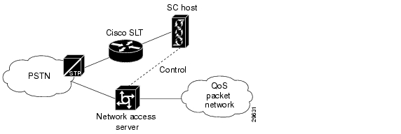
A simplex configuration is an SC node that consists of a single SC host (Sun Netra t 112x) operating with one or more Cisco SLTs. The SC application is run on the SC host and the SS7 signaling links are terminated on the Cisco SLT. An IP control LAN is used to interconnect the host server with the Cisco SLTs. One or more network access servers provide bearer channel termination. See Figure 2-1.
Note
Figure 2-1 Simplex Configuration Example
Fault-Tolerant Configuration
A fault-tolerant configuration is similar to a simplex configuration; however, the SC host must be a Sun Netra t 1400 server, a platform with redundant components. If a redundant component fails, the backup component takes over; established calls are maintained.
Continuous-Service Configuration
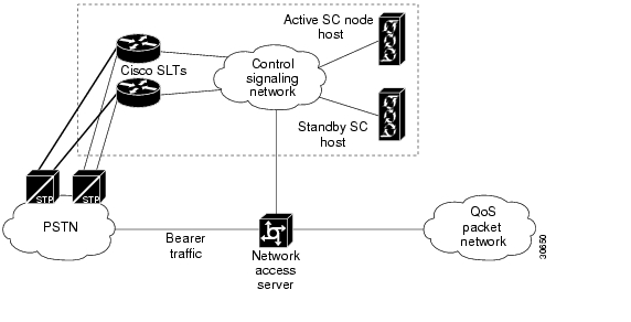
A continuous-service configuration is an SC zone that consists of a pair of SC hosts running in active mode and standby mode, operating with one or more network access servers and two or more Cisco SLTs. A heartbeat function runs continuously between the two SC hosts. When the function detects an error condition on the primary SC host, responsibility for call processing is switched to the secondary SC host. The secondary SC host becomes the primary host, and call preservation is maintained.
Figure 2-2 shows an example of a continuous-service configuration with redundant signaling links terminating on a pair of Cisco SLTs with bearer traffic terminating on the NAS.
Figure 2-2 Continuous-Service Configuration Example
Signaling Network Connections
The Cisco SS7 Interconnect for Access Servers Solution exchanges telephone control messages among the following components:
Cisco Signaling Controller—Provides signaling protocol conversion and Q.931 call control to communicate with the NASs. One signaling controller might provide signaling and call-processing services for multiple NASs in geographically distributed locations.
Cisco SLT—Handles incoming and outgoing SS7 messages (MTP layer 1 and 2) from the A-links connected to Signal Transfer Points (STPs) or F-links connected to other service switching points (SSPs). Also, when used in Drop and Insert mode, the Cisco SLT grooms off the terminating signaling link from F-links (fully associated links) and then sends the bearer channels to the NAS.
Cisco Network Access Server—Provides termination for bearer trunks. A NAS functions as a server to the bearer links. The NAS has at least two IP network interfaces: one to carry IP packet data onto one or more backbones and another to connect to the ISP's secure management, signaling, and Q.931 control network.
Your Cisco SS7 Interconnect for Access Servers Solution can be deployed with the following SS7 signaling network connections:
•
A-Link with Cisco SLT
In the A-link SLT signaling configuration, the Cisco SLT processes the two lowest-layer SS7 signaling protocols, MTP1 and MTP2. The upper layer protocols are then forwarded to the Cisco MGC host over the control signaling network. Each SLT supports two signaling network connections, and multiple SLTs can be used to support additional signaling channels or provide redundant signal paths between the signaling network and the control signaling network.
The A-link SLT signaling configuration supports V.35, T1, and E1 interfaces. The A-link SLT configuration can be used with simplex and continuous-service configurations. Each interface supports a single DS0 signaling channel.
F-Link with Cisco SLT
F-link SLT signaling configurations are similar to A-link SLT configurations. The SS7 network connection is made through fully associated links that connect an SSP or SCP to the Cisco SLT.
The F-link SLT signaling configuration supports V.35, T1, and E1 interfaces. The F-link SLT configuration can be used with simplex and continuous-service host configurations. Each interface supports a single DS0 signaling channel.
A-Link or F-Link with Cisco SLT (Drop and Insert)
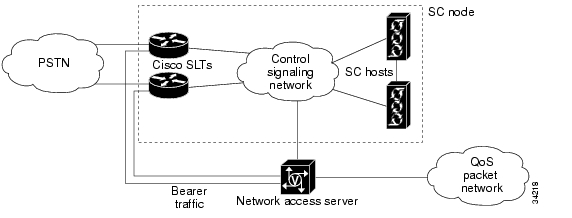
An A-link or F-link with Cisco SLT (Drop and Insert) signaling connection is similar, respectively, to an A-Link or F-link SLT signaling connection. Fully associated links directly connect an SSP or SCP to the Cisco SLT. The difference is that A-link and F-link Drop and Insert configurations support a single DS0 signaling channel per link and additional bearer traffic channels up to the capacity of the T1 or E1 link, as shown in Figure 2-3.
Note
Figure 2-3 F-Link Drop and Insert Configuration
The F-link drop and insert signaling configuration supports T1 and E1 interfaces. The Drop and Insert cards are special two-port cards designed for this application and installed in the Cisco SLT. Signal and bearer traffic enter one port together. The Cisco SLT grooms the bearer traffic and then routes it out the second port.
The F-link Drop and Insert configuration can be used with simplex and continuous-service host configurations. Each interface card supports a single DS0 signaling channel.
Control Signaling Network Options
Designing your network to handle control signaling is a complex and sophisticated task beyond the scope of this document. This section briefly describes what control signaling network options are available and some network engineering guidelines to consider.
Customer-Provided Equipment
Your control network consists of a number of hubs, switches, or routers configured together to support the number of ports in your point of presence (POP), the traffic characteristics of incoming calls, the geographic location of the Cisco SS7 Interconnect for Access Servers Solution components and the level of redundancy that you require. Other factors to consider are:
•
•
•
•
•
Control traffic (signaling) should be segregated from the bearer traffic on the QoS packet network (towards the Internet/intranet). This optimizes control traffic latency and provides added security. Redundancy in your control network can be provided by duplicating your Cisco SS7 Interconnect for Access Servers Solution components. In the event that the control network fails or connectivity to it fails, the QoS packet network is used for signaling.
In the simplest case, your Cisco SS7 Interconnect for Access Servers Solution components are co-located, and a pair of LAN switches serves as your control network. Cisco Systems recommends that the Cisco SLT not be deployed remotely from the Cisco SC2200. Remote configurations include, but are not limited to, those based on dedicated ATM connections or other similar dedicated facilities. Installing the Cisco SLT remotely from the Cisco SC2200 compromises the SS7 link stability and can eventually cause the SS7 link to fail during high traffic.
IP Connectivity with LAN
Figure 2-2 shows a sample continuous-service configuration with a mated Cisco SLT pair (for redundancy) on the control signaling network. Redundant signaling controllers support two or four Fast Ethernet connections each.
In this continuous-service configuration example, the control signaling network functions are:
•
•
•
•
•
The QoS packet network functions are:
•
•
•
IP Connectivity with WAN
Distributed IP control networks operating over a WAN is necessary when:
•
•
Note
IP Control Network Combinations
The following IP control network combinations are recommended:
•
•
•
•
•
Note
Engineering Considerations
When engineering your network, you must consider the following issues:
•
•
•
•
Cisco SS7 Interconnect for Access Servers Solution Components
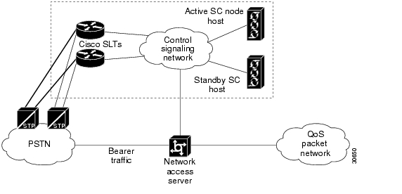
Figure 2-4 shows the components of the Cisco SS7 Interconnect for Access Servers Solution.
See the "SS7 Technology Overview" appendix for information about how the Cisco SS7 Interconnect for Access Servers Solution components operate within the SS7 hierarchy.
Figure 2-4 Cisco SS7 Interconnect for Access Servers Solution Components
SC Node Products
The SC node is the combination of hardware and software that provides the signaling controller function and transports the signaling traffic between the SC hosts and the SS7 signaling network. The SC node in the Cisco SS7 Interconnect for Access Servers Solution consists of one or more SC hosts, one or more Cisco SLTs, the signaling controller software, and ancillary equipment.
This section describes the SC hosts, signaling and Ethernet interface options, and the ancillary hardware requirements. For details on software requirements, refer to the Cisco SS7 Interconnect for Access Servers Upgrade Guide at the following location:
http://www.cisco.com/univercd/cc/td/doc/product/access/sc/rel7/soln/das/upgrade/index.htm
SC Hosts
An SC host is a Sun hardware platform running signaling controller software.
Table 2-1 lists supported SC hosts for the Cisco SC2200 product.
.
SC Host Features
The primary functions of the signaling controller is performing protocol conversion and call screening. The signaling controller is responsible for:
•
•
•
•
•
•
Table 2-2 lists the features for the SC host.
.
Signaling and Ethernet Interface Options
Table 2-3 shows the signaling and Ethernet interface options for the Cisco SC2200.
Table 2-3 SC Signaling and Ethernet Interface Options
ITK T1/E1 card
Supported
Not supported
Not supported
Supported
PTI V3.5 card
Supported
Not supported
Not supported
Supported
Sun Ethernet 1-port card
Required
Required
Not supported
Required
Cisco SLT
Supported
Supported
Supported
Supported
1 Starting with Release 2.1, Sun E450 can no longer be ordered. Cisco supports the existing installation base only.
Note
Ancillary Hardware Requirements
Table 2-4 shows the ancillary hardware requirements for the Cisco SC2200.
Table 2-4 SC Ancillary Hardware Requirements
Dataprobe Alarm Relay Unit (ARU)
Supported2
Not supported
Not supported
Supported and required only for alarm functions
Dataprobe A/B Switch
Required with use of ITK T1/E1 or PTI V.35 cards3
Not supported
Not supported
Required with use of ITK T1/E1 or PTI V.35 cards 3
Asynch Extension
Optional for simplex configurations; required with use of Dataprobe A/B switch
Not supported
Not supported
Optional for simplex configurations; required with use of Dataprobe A/B switch
1 Starting with Release 2.1, Sun E450 can no longer be ordered. Cisco supports the existing installation base only.
2 Cisco does not recommend using Dataprobe ARU. You should use the built-in alarm card and software.
3 Call preservation upon switchover or failover is not supported with the A/B switch.
Cisco SLTs
The Cisco SLT handles the incoming and outgoing SS7 messages (MTP layer 1 and 2) that arrive from the PSTN Signal Transfer Points (STPs) or Service Switching Points (SSPs). When used in the proper configurations, the Cisco SLTs improve fault tolerance by providing for multiple communications paths between the SS7 signaling network and multiple SC hosts.
Cisco SLT Features
Table 2-5 lists the features for the Cisco SLT.
Cisco Media Gateway Controller Node Manager
CMNM provides the element-specific management features for the SC node. It blends the management framework features of the Cisco Element Management Framework (CEMF) with the individual interfaces and object structures of each managed element to produce an integrated management application. Table 2-6 lists the features of CMNM.
Network Access Servers
The NAS terminates the PSTN trunks, also referred to as bearer channels, that carry the call traffic. The PSTN trunks are T1 or E1 PRI interfaces.
Note
Table 2-7 lists the features for the Cisco AS5x00 series.
LAN Switches (Optional)
The control signaling network for the Cisco SS7 Interconnect for Access Servers Solution often consists of a LAN switch and the cabling required to interconnect the solution components in an SC zone. The Cisco SS7 Interconnect for Access Servers Solution supports a LAN switch from the Cisco Catalyst switch family. This switch can extend VLANs across platforms through backbone Fast Ethernet, Gigabit, or ATM connections, when necessary.
Note
![]()
![]()
![]()
![]()
![]()
![]()
![]()
![]()
Posted: Wed Oct 20 10:07:52 PDT 2004
All contents are Copyright © 1992--2004 Cisco Systems, Inc. All rights reserved.
Important Notices and Privacy Statement.