|
|

Table Of Contents
Reference Sell Component Overview
Mobile Access Router Card Combination Cable
Serial Mobile Interface Card Cable
Fast Ethernet Switch Mobile Interface Card LED Cable
Wireless Mobile Interface Card Ethernet Jumper Cable
SSIO or SSB to DB-9 (EIA/TIA-232 DTE) Cable
Power Card, Adapter and Components
Reference Sell Component Overview
This chapter provides high-level overviews of the components that are reference sold for the Cisco 3200 Mobile Access Router. For more detailed information, including part numbers, detailed illustrations of each component, and specifications, see the Cisco 3200 Series Mobile Access Router Technical Reference. You can obtain a copy of this document through your Cisco marketing representative.
This chapter contains the following sections:
•
Mobile Access Router Card Combination Cable
•
•
•
•
•
•
•
•
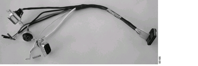
Mobile Access Router Card Combination Cable
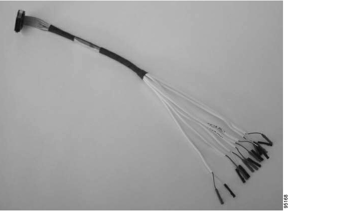
The Mobile Access Router Card (MARC) combination cable connects to the MARC through a 34-pin MARC receptacle. The design provides the following contacts, connectors, and hardware:
•
•
•
•
•
•
Figure 2-1 shows the MARC combination cable.
Figure 2-1 MARC Combination Cable
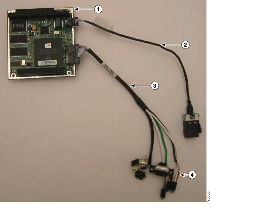
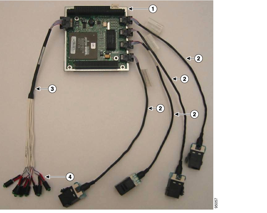
Figure 2-2 shows the MARC with the MARC combination cable, a standard Ethernet cable, and LEDs (sold separately) attached. For information on the Ethernet cable, see the "Ethernet Cable" section.
Figure 2-2 MARC with Cables
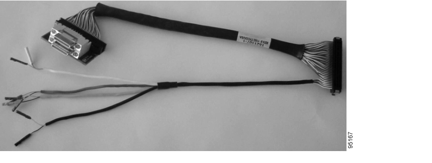
Serial Mobile Interface Card Cable
The Serial Mobile Interface Card (SMIC) cable connects to the SMIC by means of a 60-pin receptacle. The design provides the following contacts and connectors:
•
•
•
Figure 2-3 shows the SMIC cable.
Figure 2-3 SMIC Cable
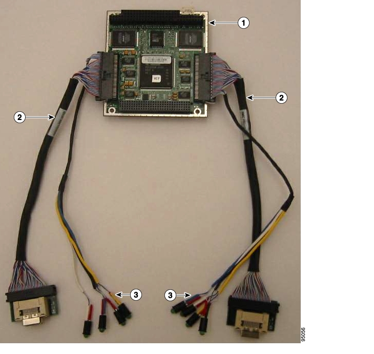
Figure 2-4 shows a SMIC with two SMIC cables and LEDs (sold separately) attached to it.
Figure 2-4 SMIC with Cables
Fast Ethernet Switch Mobile Interface Card LED Cable
The Fast Ethernet Switch Mobile Interface Card (FESMIC) LED cable connects to the FESMIC by means of a 20-pin receptacle. The design provides eight sets of contacts for the LEDs (a link and an activity LED for each Ethernet port).
Figure 2-5 shows the FESMIC LED cable.
Figure 2-5 FESMIC LED Cable
Figure 2-6 shows a 4-port FESMIC with a FESMIC LED cable, four standard Ethernet cables, and LEDs (sold separately) attached. For information on the Ethernet cables, see the "Ethernet Cable" section.
Figure 2-6 4-Port FESMIC with Cables
Ethernet Cable
This section describes the standard (non-IP67-rated) Ethernet cable.
The standard Ethernet cables connect to the MARC and FESMIC by means of a 10-pin receptacle. It provides a snap-fit, panel-mount RJ-45 receptacle with housing.
Figure 2-7 shows a standard Ethernet cable.
Figure 2-7 Standard Ethernet Cable
One Ethernet cable (standard or IP67-rated) is required per MARC while four to two Ethernet cables are required per FESMIC. Figure 2-2 shows a MARC configured with Ethernet cables. Figure 2-6 shows a 4-port FESMIC configured with Ethernet cables.
IP67-Rated Ethernet Cable
This section describes the IP67-rated Ethernet cable.
Note
The IP67-rated Ethernet cables connect to the MARC and FESMIC by means of a 10-pin receptacle. It provides a panel-mount RJ-45 receptacle with housing.
Figure 2-8 shows an Ethernet (IP67-rated) cable.
Figure 2-8 Ethernet (IP67-Rated) Cable
One Ethernet (IP67-rated or standard) cable is required per MARC while four to two Ethernet cables are required per FESMIC. Figure 2-2 shows a MARC configured with Ethernet cables. Figure 2-6 shows a 4-port FESMIC configured with Ethernet cables.
Wireless Mobile Interface Card Ethernet Jumper Cable
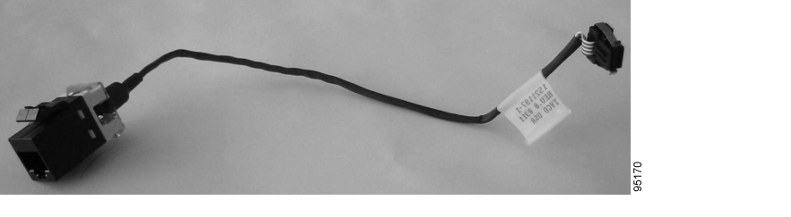
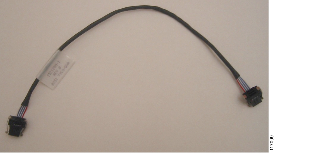
The Wireless Mobile Interface Card (WMIC) Ethernet jumper cable connects the WMIC 10-pin Ethernet header to another 10-pin Ethernet header. For best performance, connect the cable to the MARC when the WMIC is being used as an uplink.
Figure 2-9 shows the WMIC Ethernet jumper cable.
Figure 2-9 WMIC Ethernet Jumper Cable
Note
WMIC Console and LED Cable
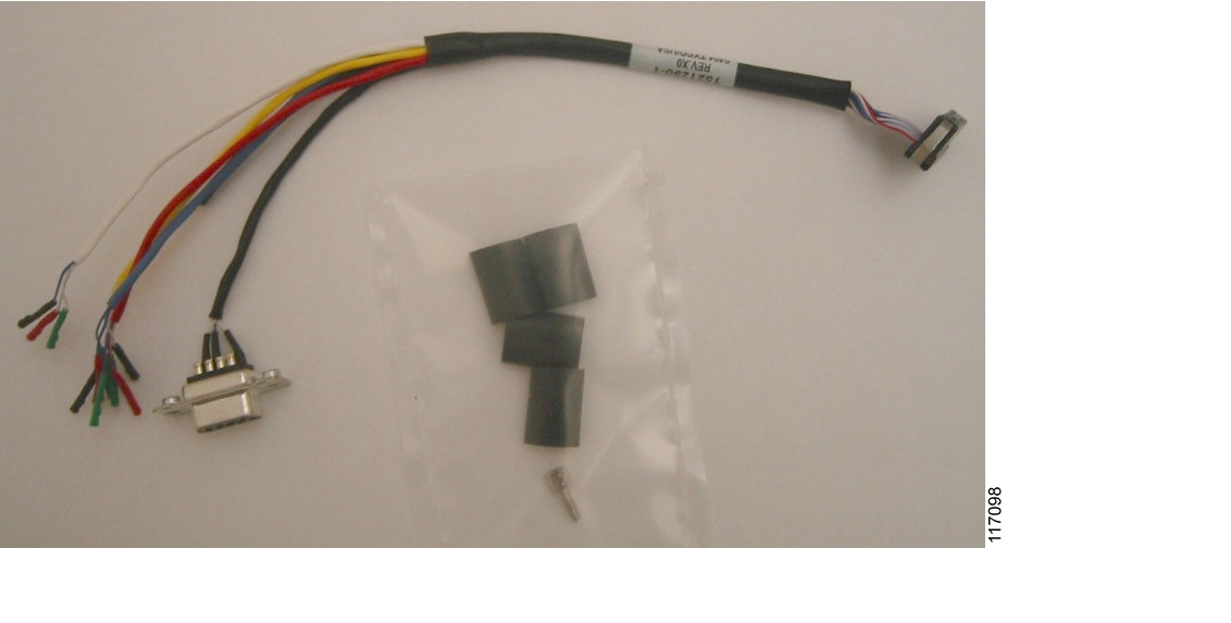
The WMIC console and LED cable assembly connects to the WMIC 24-pin multifunction header through a mating receptacle. It also provides a panel mount DB-9 for the WMIC console connector and four sets of contacts for tri-color LEDs. Typical mounting hardware for the DB-9 and heat shrink sleeves for the LEDs are included, as depicted in Figure 2-10.
Figure 2-10 shows the WMIC console and LED cable assembly.
Figure 2-10 WMIC Console and LED Cable Assembly
Note
WMIC Antenna Cable
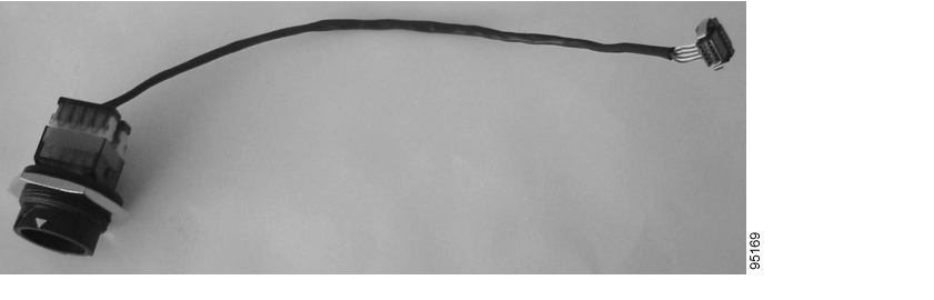
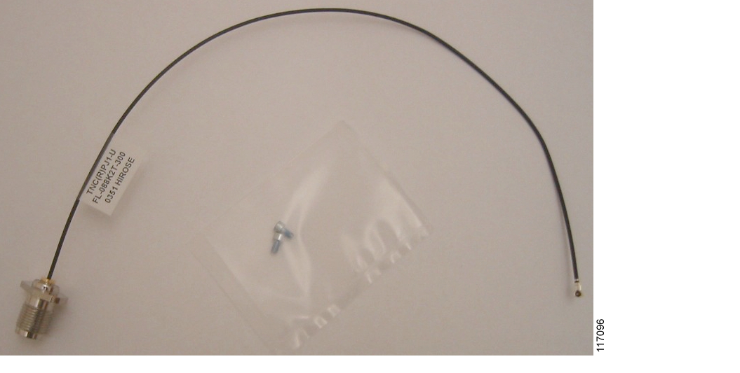
On one end, the WMIC antenna cable connects to the WMIC through a U.FL connector. The other end allows for a panel-mount connection to the end cap. This provides a reverse-polarity threaded BNC (TNC) connection for external antennas.
Figure 2-11 shows the antenna cable. Typical mounting hardware is included.
Figure 2-11 WMIC Antenna Cable
Note
WMIC with Cables
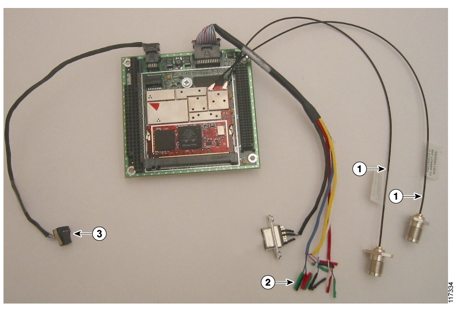
Figure 2-12 shows a WMIC with a WMIC Ethernet jumper cable, a WMIC console and LED cable, and two WMIC antenna cables are attached.
Figure 2-12 WMIC with Cables
WMIC antenna cables
WMIC console and LED cable
WMIC Ethernet jumper cable
WMIC Ethernet jumper cable
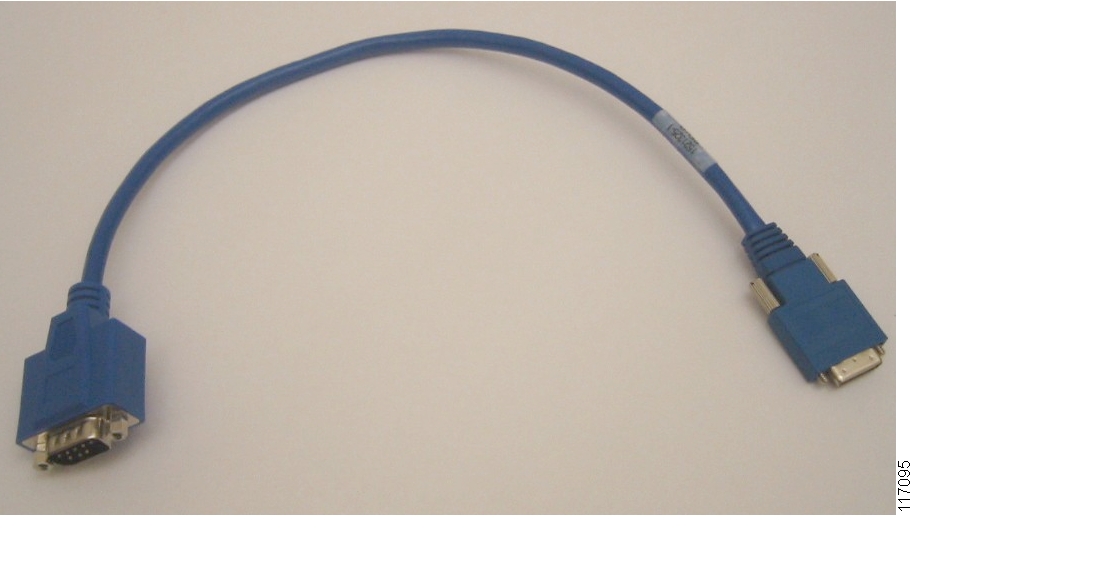
SSIO or SSB to DB-9 (EIA/TIA-232 DTE) Cable
The synchronous serial input/output (SSIO) or SSB to DB-9 (EIA/TIA-232 DTE) cable converts the SSIO or SSB connectors located on the SMIC cable to DB9 (EIA/TIA-232 DTE) for modem interfaces.
Figure 2-13 shows the SSIO or SSB to DB-9 (EIA/TIA-232 DTE) cable.
Figure 2-13 SSIO or SSB to DB-9 Cable
LEDs
Three types of LEDs are reference sold for the Cisco 3200 Mobile Access Router: IP67-rated LEDs, standard LEDs, and tri-color LEDs. Either the IP-67 rated LEDs or the standard LEDs can be used with the MARC combination cable, SMIC cable, and FESMIC LED cable. The tri-color LEDs can be used with the WMIC console and LED cable.
These LEDs have been tested for use with Cisco 3200 Mobile Access Router cable assemblies.
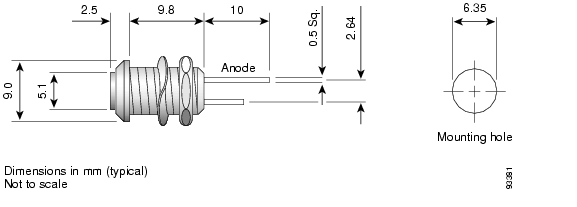
The IP67-rated green LED is panel mountable (hardware provided), and ruggedized, and it has a low profile. Figure 2-14 shows an IP67-rated LED.
Figure 2-14 IP67-Rated LED
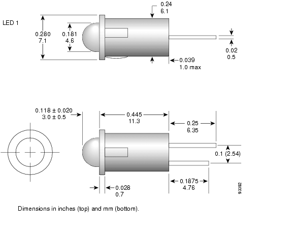
The standard LED is panel mountable (friction fit). Figure 2-15 shows a standard LED.
Figure 2-15 Standard LED
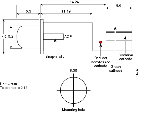
The tri-color LEDs are for use with the WMIC console and LED cable. The three colors are red, amber, and green. The tri-color LED is panel mountable (Friction fit). It is not IP-67 rated.
Figure 2-16 shows a tri-color LED.
Figure 2-16 Tri-Color LED
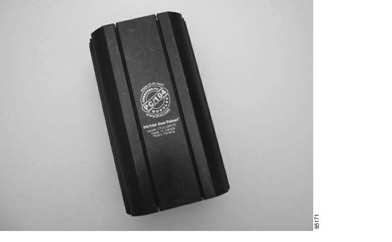
Enclosure
The 11-inch enclosure is made of extruded aluminum, and is PC/104 compatible. The enclosure has internal stack vibration mounts, supports input/output (I/O) end caps, and is on external vibration mount. Figure 2-17 shows the enclosure.
Figure 2-17 Enclosure
End Caps
The following end caps are being reference sold for the Cisco 3200 Mobile Access Router:
•
•
The end caps can be modified for the appropriate Cisco card stack configuration. SIs should work directly with the third-party vendor to obtain end caps for other configurations.
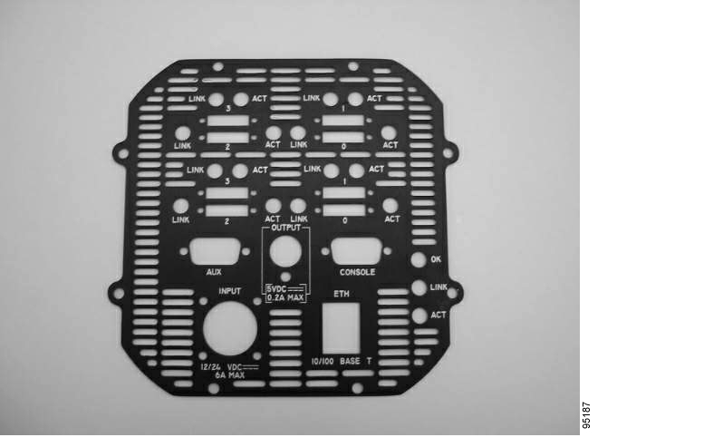
Figure 2-18 shows the 8-port serial end cap that is to be used with the MARC and 4-port SMIC. The 8-port serial end cap is vented, labeled, and made of aluminum. It is designed to be used with the enclosure referenced in this document. The end cap provides panel openings for all the connectors and LEDs associated with one power card, one MARC, and two 4-port SMICs.
Figure 2-18 MARC and Two SMICs End Cap
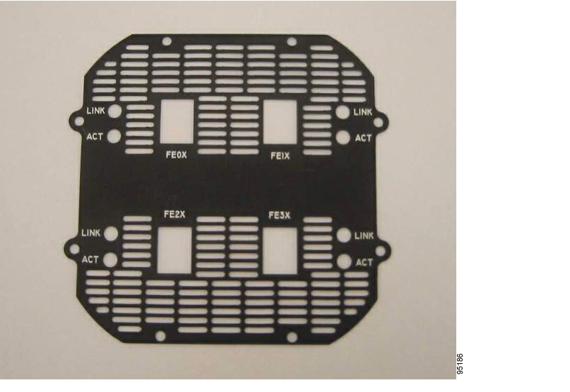
Figure 2-19 shows the 4-port end cap to be used with the 4-port FESMIC. The aluminum 4-port FESMIC end cap is vented and labeled and was designed for use with the enclosure referenced in this document. The end cap provides panel openings for all the connectors and LEDs associated with one 4-port FESMIC.
Figure 2-19 Four-Port FESMIC End Cap
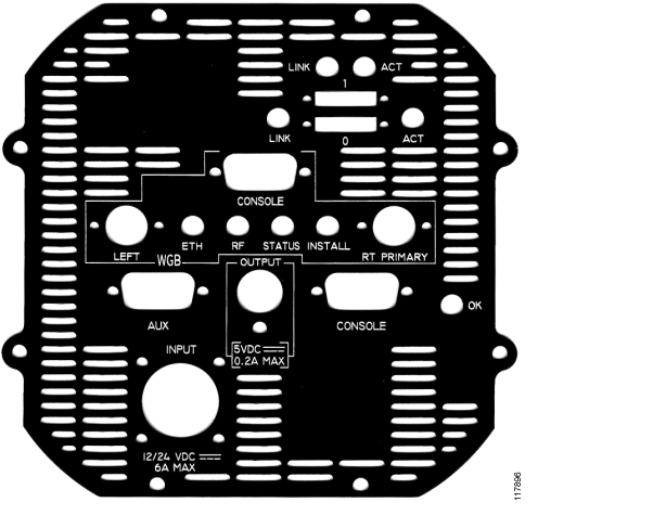
Figure 2-20 shows the 2-port serial, MARC and WMIC-WGB (workgroup bridge) end cap. The aluminum end cap is vented, labeled, and was designed to be used with the enclosure referenced in this document. It provides panel openings for all connectors and LEDs associated with one power card, one MARC, two 4-port SMICs, and one WMIC
Figure 2-20 2-Port Serial, MARC, and WMIC-WGB (Workgroup Bridge) End Cap
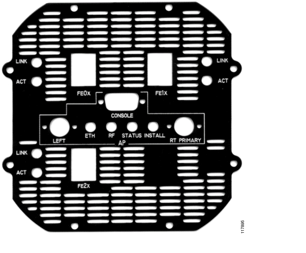
Figure 2-21 shows the 3-port Fast Ethernet and WMIC-AP (access point) end cap. The aluminum end cap is vented and labeled. It was designed for use with the enclosure described in this document. The end cap provides panel openings for all connectors and LEDs associated with one FESMIC and one WMIC that is being used as an AP.
Figure 2-21 3-Port Fast Ethernet and WMIC-AP End Cap
Power Card, Adapter and Components
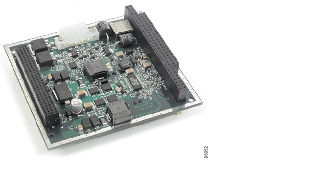
The DC/DC power card is a ruggedized, application-specific, triple-output, PC/104—Plus-compatible converter. It accepts 12-VDC or 24-VDC inputs from a vehicle battery system and provides fully protected 3.3V, 5V, and 12V outputs. The AC/DC power adapter provides a compatible DC input when not being used in a 12-VDC or 24-VDC application.
Figure 2-22 shows the DC/DC power card.
Figure 2-22 DC/DC Power Card
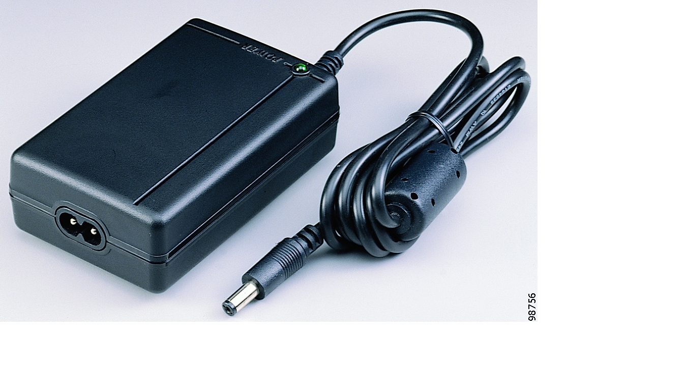
Other power components that are being reference sold include a power adapter, internal power cables, external power cables, and an external power adapter. Figure 2-23 shows the power adapter.Figure 2-23 AC/DC Power Adapter
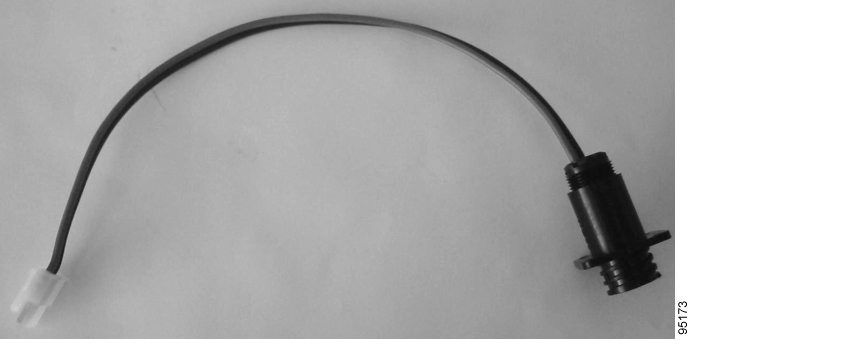
Figure 2-24 shows the internal power cable.
Figure 2-24 Internal Power Cable
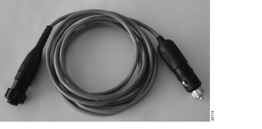
Figure 2-25 shows the external power cable.
Figure 2-25 External Power Cable
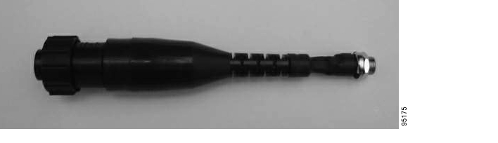
Figure 2-26 shows the external power adapter.
Figure 2-26 External Power Adapter
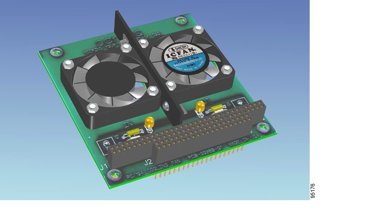
Fan Card
The fan card referenced in this document has been tested on each end of the Cisco 3200 Mobile Access Router. It helps to circulate air over the cards and to remove heat from the enclosure. For more information on recommended fan card use, refer to the Cisco 3200 Series Mobile Access Router Technical Reference.
Figure 2-27 shows the fan card.
Figure 2-27 Fan Card
Configuration Examples
This section provides configuration examples for the Cisco 3200 Mobile Access Router.
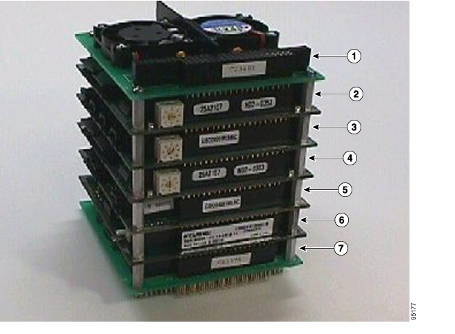
Figure 2-28 shows an example of a configuration with one 4-port FESMIC, one 4-port SMIC, one MARC, two fan cards, and one power card. No enclosure is shown in the figure.
Figure 2-28 Configuration Example with One 4-Port FESMIC, One 4-Port SMIC, and One MARC
Figure 2-29 shows an example of a configuration with two 4-port SMICs, one 4-port FESMIC, one MARC, two fan cards, and one power card. No enclosure is shown in the figure.Figure 2-29 Configuration Example With Two Four-port SMICs, One Four-port FESMIC, and One MARC
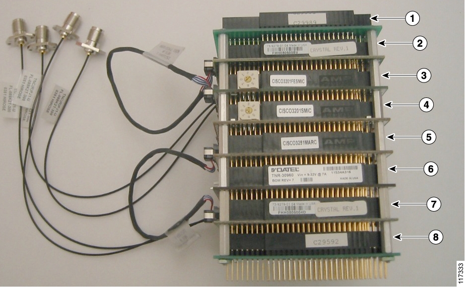
Figure 2-30 shows an example of a configuration with two WMICs, one 4-port FESMIC, one 4-port SMIC, MARC, two fan cards, and one power card. No enclosure is shown in the figure.
Note
Figure 2-30 Configuration Example with Two WMICs, One 4-Port FESMIC, One 4-Port SMIC, and One MARC
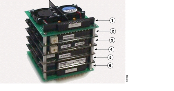
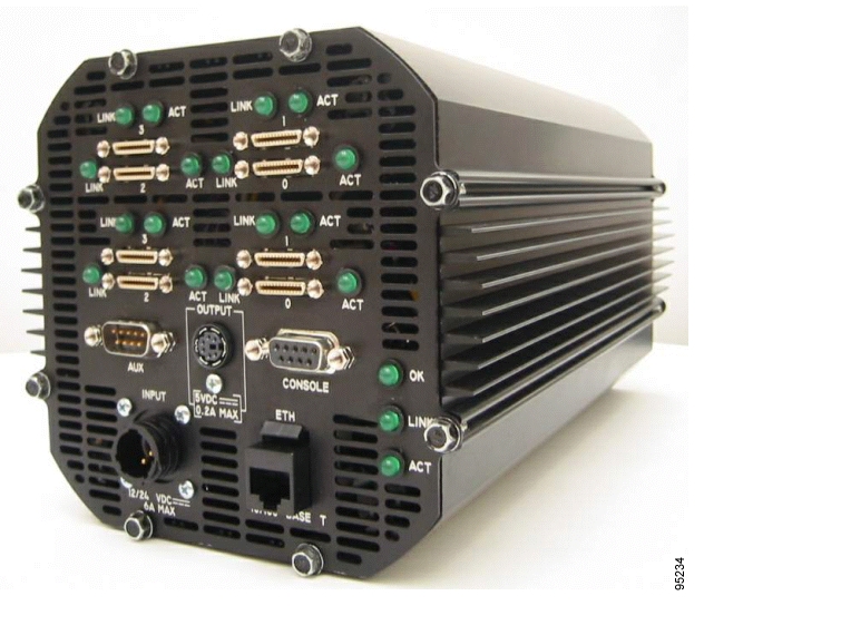
Figure 2-31 shows a configuration with one MARC and two 4-port SMICs in an enclosure.Figure 2-31 Example of a Configured Cisco 3200 Mobile Access Router with one MARC, two 4-port SMICs, and one 4-port FESMIC
Figure 2-32 shows a configuration with one MARC, two 4-port SMICs and one 4-port FESMIC in an enclosure.
Figure 2-32 Example of a Configured Cisco 3200 Mobile Access Router with one MARC and two 4-port SMICs, and one 4-port FESMIC
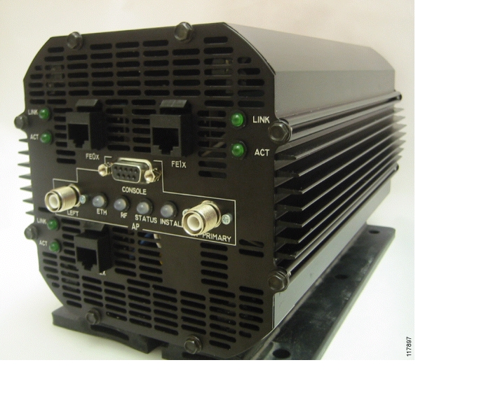
Figure 2-33 shows a configuration with one MARC, three FESMIC ports, and one WMIC port in an enclosure.
Figure 2-33 Example of a Configured Cisco 3200 Mobile Access Router with one MARC, Three FESMIC Ports, and One WMIC Port
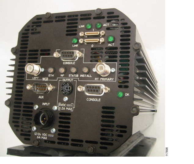
Figure 2-34 shows a configuration with one MARC, two SMIC ports, and one WMIC port in an enclosure.
Figure 2-34 Example of a Configured Cisco 3200 Mobile Access Router with one MARC, Two SMIC Ports, and One WMIC Port
![]()
![]()
![]()
![]()
![]()
![]()
![]()
![]()
Posted: Mon Oct 31 10:19:00 PST 2005
All contents are Copyright © 1992--2005 Cisco Systems, Inc. All rights reserved.
Important Notices and Privacy Statement.