|
|

Table Of Contents
Configuring Spanning Tree Protocol
Understanding Spanning Tree Protocol
Election of the Spanning-Tree Root
Creating the Spanning-Tree Topology
Spanning-Tree Interface States
Displaying Spanning-Tree Status
Configuring Spanning Tree Protocol
This chapter descibes how to configure Spanning Tree Protocol (STP) on the Cisco wireless mobile interface card (WMIC).
Note
For complete syntax and usage information for the commands used in this chapter, refer to the Cisco IOS Command Reference for Access Points and Bridges for this release.
Understanding Spanning Tree Protocol
This section describes how spanning-tree features work.
STP Overview
STP is a Layer 2 link management protocol that provides path redundancy while preventing loops in the network. For a Layer 2 network to function properly, only one active path can exist between any two stations. Spanning-tree operation is transparent to end stations, which cannot detect whether they are connected to a single LAN segment or to a LAN of multiple segments.
When you create fault-tolerant internetworks, you must have a loop-free path between all nodes in a network. The spanning-tree algorithm calculates the best loop-free path throughout a Layer 2 network. Infrastructure devices such as wireless bridges and switches send and receive spanning-tree frames, called bridge protocol data units (BPDUs), at regular intervals. The devices do not forward these frames but use them to construct a loop-free path.
Multiple active paths among end stations cause loops in the network. If a loop exists in the network, end stations might receive duplicate messages. Infrastructure devices might also learn end-station MAC addresses on multiple Layer 2 interfaces. These conditions result in an insecure network.
STP defines a tree with a root device and a loop-free path from the root to all infrastructure devices in the Layer 2 network.
Note
STP forces redundant data paths into a standby (blocked) state. If a network segment in the spanning tree fails and a redundant path exists, the spanning-tree algorithm recalculates the spanning-tree topology and activates the standby path.
When two interfaces are part of a loop, the spanning-tree port priority and path cost settings determine which interface is put in the forwarding state and which is put in the blocking state. The port priority value represents the location of an interface in the network topology and how well it is located to pass traffic. The path cost value represents media speed.
The bridge supports both per-VLAN spanning tree (PVST) and a single 802.1q spanning tree without VLANs. The bridge cannot run 802.1s multiple spanning tree (MST) or 802.1d Common Spanning Tree, which map multiple VLANs into a one-instance spanning tree.
The bridge maintains a separate spanning-tree instance for each active VLAN configured on it. A bridge ID, consisting of the bridge priority and the MAC address, is associated with each instance. For each VLAN, the bridge with the lowest bridge ID becomes the spanning-tree root for that VLAN.
Bridge Interoperability
Cisco bridges are interoperable when STP is enabled and no VLANs are configured. This configuration is the only one possible, for the following reasons:
•
•
•
Therefore, the best configuration for STP interoperability is to have the bridge STP feature enabled and VLANs not configured.
Note
Bridge Protocol Data Units
The stable, active spanning-tree topology of a network is determined by the following factors:
•
•
•
When the bridges in a network are powered up, each bridge functions as the STP root. The bridges send configuration BPDUs through the Ethernet and radio ports. The BPDUs communicate and compute the spanning-tree topology. Each configuration BPDU contains this information:
•
•
•
•
•
•
When a bridge receives a configuration BPDU that contains information superior (lower bridge ID, lower path cost, and so forth), it stores the information for that port. If this BPDU is received on the root port of the bridge, the bridge also forwards it with an updated message to all attached LANs for which it is the designated bridge.
If a bridge receives a configuration BPDU that contains inferior information to that currently stored for that port, it discards the BPDU. If the bridge is a designated bridge for the LAN from which the inferior BPDU was received, it sends that LAN a BPDU containing the up-to-date information stored for that port. In this way, inferior information is discarded, and superior information is propagated on the network.
A BPDU exchange results in these actions:
•
•
•
•
•
•
Election of the Spanning-Tree Root
All bridges in the Layer 2 network that are participating in STP gather information about other bridges in the network by exchanging BPDU data messages. This message exchange results in these actions:
•
•
•
For each VLAN, the bridge with the highest bridge priority (the lowest numerical priority value) is elected as the spanning-tree root. If all bridges are configured with the default priority (32768), the bridge with the lowest MAC address in the VLAN becomes the spanning-tree root. The bridge priority value occupies the most significant bits of the bridge ID.
When you change the bridge priority value, you change the probability that the bridge will be elected as the root device. Configuring a higher value decreases the probability; a lower value increases the probability.
The spanning-tree root is the logical center of the spanning-tree topology. Paths that are not needed to reach the spanning-tree root from anywhere in the network are placed in the spanning-tree blocking mode.
BPDUs contain information about the sending bridge and its ports, including bridge and MAC addresses, bridge priority, port priority, and path cost. STP uses this information to elect the spanning-tree root and root port for the network and the root port and designated port for each LAN segment.
Spanning-Tree Timers
Table 7-1 describes the timers that affect the entire spanning-tree performance.
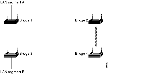
Creating the Spanning-Tree Topology
In Figure 7-1, bridge 4 is elected as the spanning-tree root, under the assumption that the priority of all the bridges is set to the default (32768) and bridge 4 has the lowest MAC address. However, because of traffic patterns, number of forwarding interfaces, or link types, bridge 4 might not be the ideal spanning-tree root. By increasing the priority (lowering the numerical value) of the ideal bridge so that it becomes the spanning-tree root, you force a spanning-tree recalculation to form a new topology with the ideal bridge as the spanning-tree root.
Figure 7-1 Spanning-Tree Topology
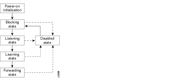
Spanning-Tree Interface States
Propagation delays can occur when protocol information passes through a wireless LAN. As a result, topology changes can take place at different times and at different places in the network. When an interface transitions directly from nonparticipation in the spanning-tree topology to the forwarding state, it can create temporary data loops. Interfaces must wait for new topology information to propagate through the LAN before starting to forward frames. They must allow the frame lifetime to expire for forwarded frames that have used the old topology.
Each interface on a bridge using spanning tree exists in one of these states:
•
•
•
•
•
An interface moves through these states:
•
•
•
•
•
Figure 7-2 illustrates how an interface moves through the states.
Figure 7-2 Spanning-Tree Interface States
When you enable STP on the bridge, the Ethernet and radio interfaces go through the blocking state and the transitory states of listening and learning. STP stabilizes each interface at the forwarding or blocking state.
When the spanning-tree algorithm places a Layer 2 interface in the forwarding state, this process occurs:
1.
2.
3.
4.
Blocking State
An interface in the blocking state does not participate in frame forwarding. After initialization, a BPDU is sent to the bridge's Ethernet and radio ports. A bridge initially functions as the spanning-tree root until it exchanges BPDUs with other bridges. This exchange establishes which bridge in the network is the spanning-tree root. If there is only one bridge in the network, no exchange occurs, the forward-delay timer expires, and the interfaces move to the listening state. An interface always enters the blocking state when you enable STP.
An interface in the blocking state performs as follows:
•
•
•
Note
Listening State
The listening state is the first state an interface enters after the blocking state. The interface enters this state when STP determines that the interface should participate in frame forwarding.
An interface in the listening state performs as follows:
•
•
•
Learning State
An interface in the learning state prepares to participate in frame forwarding. The interface enters the learning state from the listening state.
An interface in the learning state performs as follows:
•
•
•
Forwarding State
An interface in the forwarding state forwards frames. The interface enters the forwarding state from the learning state.
An interface in the forwarding state performs as follows:
•
•
•
Disabled State
An interface in the disabled state does not participate in frame forwarding or in the spanning tree. An interface in the disabled state is nonoperational.
A disabled interface performs as follows:
•
•
•
Configuring STP Features
You complete three major steps to configure STP on the WMIC:
1.
2.
3.
These sections provide information on STP configuration:
Default STP Configuration
STP is disabled by default. Table 7-2 lists the default STP settings when you enable STP.
The radio and Ethernet interfaces and the native VLAN on the bridge are assigned to bridge group 1 by default. When you enable STP and assign a priority on bridge group 1, STP is enabled on the radio and Ethernet interfaces and on the primary VLAN, and those interfaces adopt the priority assigned to bridge group 1. You can create bridge groups for subinterfaces and assign different STP settings to those bridge groups.
Configuring STP Settings
To configure STP on the WMIC, follow these steps, beginning in privileged EXEC mode:
STP Configuration Examples
These configuration examples show how to enable STP on root and non-root bridges with and without VLANs:
•
Root Device Without VLANs
This example shows the configuration of a root device with no VLANs configured and with STP enabled:
hostname master-bridge-southip subnet-zero!bridge irb!interface Dot11Radio0no ip addressno ip route-cache!ssid tsunamiauthentication openguest-mode!speed basic-6.0 9.0 12.0 18.0 24.0 36.0 48.0 54.0rts threshold 2312station-role rootno cdp enableinfrastructure-clientbridge-group 1!interface FastEthernet0no ip addressno ip route-cacheduplex autospeed autobridge-group 1!interface BVI1ip address 1.4.64.23 255.255.0.0no ip route-cache!ip default-gateway 1.4.0.1bridge 1 protocol ieeebridge 1 route ipbridge 1 priority 9000!line con 0exec-timeout 0 0line vty 0 4loginline vty 5 15login!endNon-Root Bridge Without VLANs
This example shows the configuration of a non-root bridge with STP enabled and no VLANs configured:
hostname client-bridge-northip subnet-zero!bridge irb!interface Dot11Radio0no ip addressno ip route-cache!ssid tsunamiauthentication openguest-mode!speed basic-6.0 9.0 12.0 18.0 24.0 36.0 48.0 54.0rts threshold 2312station-role non-rootno cdp enablebridge-group 1!interface FastEthernet0no ip addressno ip route-cacheduplex autospeed autobridge-group 1 path-cost 40!interface BVI1ip address 1.4.64.24 255.255.0.0no ip route-cache!bridge 1 protocol ieeebridge 1 route ipbridge 1 priority 10000!line con 0line vty 0 4loginline vty 5 15login!endRoot Device with VLANs
This example shows the configuration of a root device with VLANs configured with STP enabled:
hostname master-bridge-hq!ip subnet-zero!ip ssh time-out 120ip ssh authentication-retries 3!bridge irb!interface Dot11Radio0no ip addressno ip route-cache!ssid vlan1vlan 1infrastructure-ssidauthentication open!speed basic-6.0 9.0 12.0 18.0 24.0 36.0 48.0 54.0rts threshold 2312station-role rootno cdp enableinfrastructure-client!interface Dot11Radio0.1encapsulation dot1Q 1 nativeno ip route-cacheno cdp enablebridge-group 1!interface Dot11Radio0.2encapsulation dot1Q 2no ip route-cacheno cdp enablebridge-group 2!interface Dot11Radio0.3encapsulation dot1Q 3no ip route-cachebridge-group 3bridge-group 3 path-cost 500!interface FastEthernet0no ip addressno ip route-cacheduplex autospeed auto!interface FastEthernet0.1encapsulation dot1Q 1 nativeno ip route-cachebridge-group 1!interface FastEthernet0.2encapsulation dot1Q 2no ip route-cachebridge-group 2!interface FastEthernet0.3encapsulation dot1Q 3no ip route-cachebridge-group 3!interface BVI1ip address 1.4.64.23 255.255.0.0no ip route-cache!ip default-gateway 1.4.0.1bridge 1 protocol ieeebridge 1 route ipbridge 1 priority 9000bridge 2 protocol ieeebridge 2 priority 10000bridge 3 protocol ieeebridge 3 priority 3100!line con 0exec-timeout 0 0line vty 5 15!endNon-Root Bridge with VLANs
This example shows the configuration of a non-root bridge with VLANs configured with STP enabled:
hostname client-bridge-remote!ip subnet-zero!ip ssh time-out 120ip ssh authentication-retries 3!bridge irb!interface Dot11Radio0no ip addressno ip route-cache!ssid vlan1vlan 1authentication openinfrastructure-ssid!speed basic-6.0 9.0 12.0 18.0 24.0 36.0 48.0 54.0rts threshold 2312station-role non-rootno cdp enable!interface Dot11Radio0.1encapsulation dot1Q 1 nativeno ip route-cacheno cdp enablebridge-group 1!interface Dot11Radio0.2encapsulation dot1Q 2no ip route-cacheno cdp enablebridge-group 2!interface Dot11Radio0.3encapsulation dot1Q 3no ip route-cacheno cdp enablebridge-group 3!interface FastEthernet0no ip addressno ip route-cacheduplex autospeed auto!interface FastEthernet0.1encapsulation dot1Q 1 nativeno ip route-cachebridge-group 1!interface FastEthernet0.2encapsulation dot1Q 2no ip route-cachebridge-group 2!interface FastEthernet0.3encapsulation dot1Q 3no ip route-cachebridge-group 3bridge-group 3 path-cost 400!interface BVI1ip address 1.4.64.24 255.255.0.0no ip route-cache!bridge 1 protocol ieeebridge 1 route ipbridge 1 priority 10000bridge 2 protocol ieeebridge 2 priority 12000bridge 3 protocol ieeebridge 3 priority 2900!line con 0line vty 5 15!endDisplaying Spanning-Tree Status
To display the spanning-tree status, use one or more of the commands in Table 7-3 in privileged EXEC mode:
For information about other keywords for the show spanning-tree privileged EXEC command, refer to the Cisco IOS Command Reference for Cisco Access Points and Bridges.
![]()
![]()
![]()
![]()
![]()
![]()
![]()
![]()
Posted: Wed Feb 13 22:47:34 PST 2008
All contents are Copyright © 1992--2008 Cisco Systems, Inc. All rights reserved.
Important Notices and Privacy Statement.