|
|

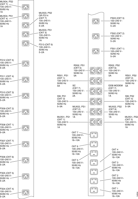
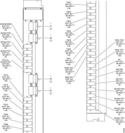
The illustrations and tables in this appendix show the locations of the AC power strip and DC busbar power outlets.
 | Caution You must connect each shelf's power cable only to that shelf's designated power outlet; outlets are designated to both distribute loads equally and create power redundancies where required. If you ignore Cisco's power designations, you risk overloading a circuit in your system or loosing power redundancies, thereby increasing risk of system inoperability during unstable power periods. |
Appendix B provides specifications for all Cisco AccessPath Model 531 system cables.


| Shelf or Module | Current Rating | Power Feed Circuit | Outlet Number |
|---|---|---|---|
OOB modem | 2A | A1 | 29 |
MUX04, PS2 | 2A | B2 | 28 |
MUX04, PS1 | 2A | A1 | 27 |
MUX03, PS1 | 2A | A1 | 26 |
FS14 | 10A | B2 | 25 |
FS13 | 10A | A2 | 24 |
FS12 | 10A | B2 | 23 |
FS11 | 10A | B1 | 22 |
FS10 | 10A | A2 | 21 |
FS09 | 10A | A1 | 20 |
FS08 | 10A | B2 | 19 |
FS07 | 10A | B1 | 18 |
FS06 | 10A | A2 | 17 |
FS05 | 10A | A1 | 16 |
FS04 | 10A | B2 | 15 |
FS03 | 10A | B1 | 14 |
FS02 | 10A | A2 | 13 |
FS01 | 10A | A1 | 12 |
RS02, PS2 | 14A | B2 | 11 |
RS02, PS1 | 14A | A2 | 10 |
RS01, PS2 | 14A | B1 | 9 |
RS01, PS1 | 14A | A1 | 8 |
SC | 5A | B1 | 7 |
SW, PS2 | 7A | B1 | 6 |
SW, PS1 | 7A | A1 | 5 |
MUX02, PS2 | 2A | B1 | 4 |
MUX02, PS1 | 2A | A1 | 3 |
MUX01, PS2 | 2A | B1 | 2 |
MUX01, PS1 | 2A | A1 | 1 |
![]()
![]()
![]()
![]()
![]()
![]()
![]()
![]()
Posted: Tue Jul 23 10:03:17 PDT 2002
All contents are Copyright © 1992--2002 Cisco Systems, Inc. All rights reserved.
Important Notices and Privacy Statement.