|
|

Your Cisco AccessPath Integrated Access System was configured as you requested before leaving the factory. If, however, you want to install or remove the front door of the AccessPath system or add or remove Access Server Shelves or Router Shelves later on, use the processes and procedures in this appendix.
The AccessPath system is scalable, which means you can expand the number of shelves in the stack as your network needs grow, or remove shelves (for use elsewhere) as you shift traffic to other network segments. For example, if you use the AccessPath system for single-channel calls only, you might want to remove the second Router Shelf, replacing it with two Access Server Shelves. Or you might want to swap out two Access Server Shelves for a second Router Shelf to accommodate a heavy ISDN load.
This appendix contains the following maintenance sections:
In addition, this appendix describes how to scale your AccessPath system to meet changing needs or newly assigned priorities, and includes the following sections on scaling:
Note This guide covers only the hardware aspects of the Cisco AccessPath Integrated Access System maintenance for software maintenance issues, refer to the Cisco AccessPath Integrated Access System Software Configuration Guide or the Installing Cisco AccessPath Manager document.
The AccessPath system ships with a door included in its crate. If you want to install the door, follow these steps:
Step 2 Hold the door in place where it will be installed.
Step 3 Have a second person squeeze together the pins on the hinges and move them into the slots that keep them open. See Figure A-1.
You may need to remove the AccessPath system door in order to improve ventillation for the shelves or to provide better access to port adapters on the shelves to remove or replace them.
Use the following steps to remove the Cisco AccessPath Integrated Access System door:
Step 2 Have a second person squeeze together the pins on the hinges and move them into the slots that keep them open. See Figure A-1.
This section guides you through the installation of an additional Access Server Shelf in the AccessPath rack and includes the following sections:
You need the following tools and parts to install the access server:
This section describes how to install an additional Access Server Shelf in the AccessPath system. The procedure includes the following steps:
This section describes how to install the Access Server Shelf in the AccessPath system.
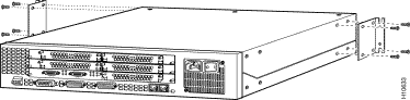
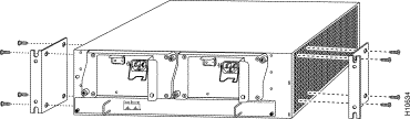
Step 2 Using the screws provided, attach the brackets to each side of the front of the Access Server Shelf, as shown in Figure A-3.
Note For correct cable alignment, the Access Server Shelf must be installed so that the rear panel (port adapter side) faces towards the front (cable harness side) of the AccessPath system.
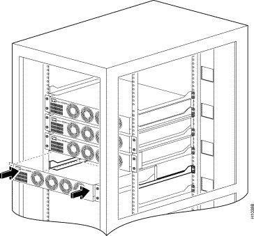
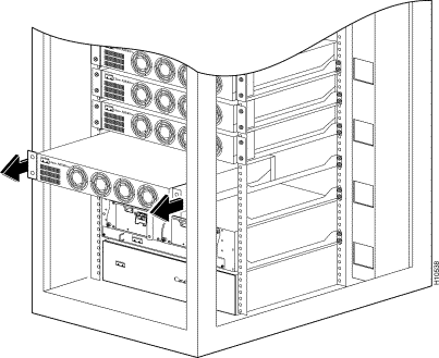
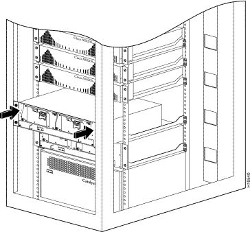
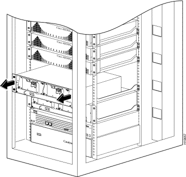
Step 3 Slide the Access Server Shelf into the rack using the preinstalled slide rails as guides. See Figure A-4.
Step 4 Secure the Access Server Shelf to the rack using screws you provide.
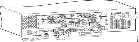
This section describes the connection of cables to the Access Server Shelf.
Each of the Access Server Shelves uses a Model BL50 10BaseT IEEE 802.3 Transceiver to connect from its Ethernet LAN port to the Router Shelf.
For information on the transceivers and their factory switch settings, diagnostic lights, and pinouts, refer to the section "10BaseT Transceivers" in the appendix "Cabling Specifications for the Cisco AccessPath Integrated Access System."
Note The transceivers have four switch settings and seven diagnostic lights. The switches should be kept at the factory settings, unless changes are recommended by Cisco-certified maintenance personnel.
| Connection Number | Cable Labeling | Access Server Shelf Connection |
|---|---|---|
Access Server Shelf, Ethernet LAN Port 0, through a Model BL50 10BaseT IEEE 802.3 Transceiver. |
||
Step 2 For AC power configurations, connect the Access Server Shelf's power supply to the power strip receptacle designated for that Access Server Shelf. See Table A-2 for a list of these connections.
| Access Server Shelf (From Top to Bottom) |
Power Receptacle (From Top to Bottom) |
|---|---|
Step 3 Turn ON power to the new Access Server Shelf.
You are now ready to configure the software on the new Access Server Shelf. For software configuration procedures, refer to the Cisco AccessPath Integrated Access System Software Configuration Guide or the Installing Cisco AccessPath Manager document.
This section guides you through the removal of an Access Server Shelf from the AccessPath rack and includes the following sections:
You need the following tools and parts to install the access server:
In order to remove an Access Server Shelf, follow these steps.
Step 2 From the front of the AccessPath system, uncable the Access Server Shelf. Remove all data connection and power cables where they enter the Access Server Shelf. Secure the loose data cables to the cable housing.
Step 3 From the back of the system, unbolt the Access Server Shelf from the rack.
Step 4 Remove the Access Server Shelf. See Figure A-6.
You are now ready to configure the software on the AccessPath system to account for the removal of the Access Server Shelf. For software configuration procedures, refer to the Cisco AccessPath Integrated Access System Software Configuration Guide or the Installing Cisco AccessPath Manager document.
This section guides you through the installation of an additional Router Shelf in the AccessPath rack and includes the following sections:
You need the following tools and parts to install the access server:
If your AccessPath system has 11 or 12 Access Server Shelves, you must remove the bottom two Access Server Shelves in order to make room for the Router Shelf.
The procedure for adding a Router Shelf includes the following steps:
Compare your system to the one shown in Figure A-7. If your configuration looks like this (that is, if there are more than 10 Access Server Shelves), use the procedure to remove the Access Server Shelves.
Step 2 From the front of the AccessPath system, uncable the Access Server Shelf. Remove all data connection and power cables where they enter the Access Server Shelf. Secure the loose data cables to the cable housing.
Step 3 From the back of the system, unbolt the Access Server Shelf from the rack.
Step 4 Remove the Access Server Shelf. See Figure A-8.
Step 5 If there is a twelfth Access Server Shelf, remove it using the procedure outlined in Step 1 through Step 4.
Step 6 Remove the shelf guides between the bottom two Access Server Shelves, so that there is enough space for the new Router Shelf. See Figure A-9.
This section describes how to install a Router Shelf in the AccessPath system.
Step 2 Using the screws provided, attach the brackets to each side of the back of the Router Shelf, as shown in Figure A-11.
Note For correct cable alignment, the Router Shelf must be installed so that the front panel (port adapter side) faces towards the front (cable harness side) of the AccessPath system.
Step 3 Slide the Router Shelf into the rack using the preinstalled slide rails as guides. See Figure A-12.
Step 4 Secure the Router Shelf to the rack using screws you provide.
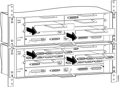
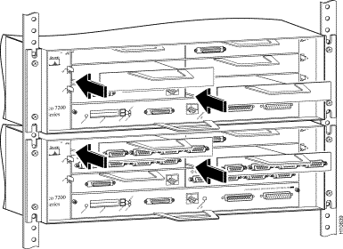
Step 2 Remove the Serial Port Adapters from slots 4 and 5 on the existing Router Shelf and the blank Port Adapter guards from slots 2 and 3 on the new Router Shelf. See Figure A-13.
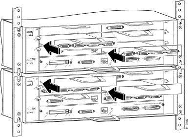
Step 3 Swap the Serial Port Adapters into slots 2 and 3 on the new Router Shelf and the blank Port Adapter guards into slots 4 and 5 on the existing Router Shelf. See Figure A-14.
The steps in this section describe the procedure for moving all of the serial lines to the proper port for a two Router Shelf configuration.
You will move the odd-numbered interface connections (to the even-numbered Access Server Shelves) to serial ports on the newly installed Router Shelf.
| Take the cable that was connected to | And connect it to |
|---|---|
Step 2 Add a cable to connect the Switch Shelf at port 1/2 to the second Router Shelf at its Fast Ethernet port 1/0. This cable was shipped with the AccessPath system and should be labeled "SW - 1/2" at one end and "RS2 - FE 1/0" at the other.
Step 3 AC power connection. Connect the second Router Shelf's first power supply to the third receptacle from the bottom on the first power strip from the bottom. Connect the second power supply to the third receptacle from the bottom on the second power strip from the bottom.
Step 4 Turn ON power to the new Router Shelf.
Now you are ready to configure the software on the new Router Shelf. For software configuration procedures, refer to the Cisco AccessPath Integrated Access System Software Configuration Guide or the Installing Cisco AccessPath Manager document.
This section describes how to remove a second Router Shelf from the Cisco AccessPath Integrated Access System.
Removal of the second Router Shelf entails removal of the physical device, and modifications to the configuration files on all Access Server Shelves in the stack and to the remaining Router Shelf.
This procedure requires that you make modifications to the Access Server Shelves before you physically remove the second Router Shelf from the stack. After the Router Shelf device is physically removed, you will modify the configuration of the remaining Router Shelf to accommodate the Access Server Shelves that were connected to it.
Topics in this section include the following:
You need the following tools and parts to install the Router Shelf:
To remove the second Router Shelf from the AccessPath system, use the procedure described below. This procedure includes the following steps:
Before physically removing the second Router Shelf device, you need to modify the AccessPath system's Stack Group Bidding Protocol (SGBP) configuration, and the system clock synchronization configuration on all Access Server shelves.
Before physically removing the second Router Shelf device, Telnet to each Access Server Shelf in the AccessPath system and perform the following tasks:
In this example, the user enters configuration mode on Access Server Shelf number 6 (nas06), removes the SGBP configuration for the second Router Shelf (offload02), and exits configuration mode.
Step 2 Disable the ntp server configuration on each of the Access Server Shelves.
In the following example, the user enters configuration mode on Access Server Shelf number 6 (nas06), removes the ntp server configuration and exits configuration mode.
Note If the second Router Shelf was used to provide a redundant backhaul connection, that backhaul connection should be removed from service at this time. It will also be necessary to change routing configurations on other routers to accommodate this change.
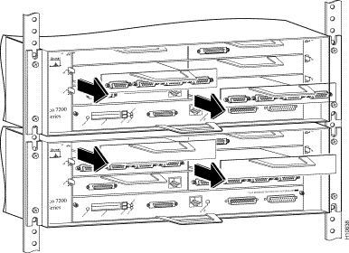
Step 2 Remove the Serial Port Adapters from slots 2 and 3 on the second (top) Router Shelf and the blank Port Adapter guards from slots 4 and 5 on the first (bottom) Router Shelf. See Figure A-15.
Step 3 Swap the Serial Port Adapters into slots 4 and 5 on the first Router Shelf and the blank Port Adapter guards into slots 2 and 3 on the second Router Shelf. See Figure A-16.
The steps in this section describe the procedure for moving all of the serial lines to the proper port for a single Router Shelf configuration.
You will move all of the connections to the Access Server Shelves to serial ports on the remaining Router Shelf.
| Take the cable that was connected to | And connect it to |
|---|---|
Step 2 Remove the cable that is connected to the Switch Shelf at port 1/2.
Step 3 Remove the cable and transceivers that connect the Router Shelves to each other.
Step 2 From the front of the AccessPath system, uncable the Router Shelf. Remove all data connection and power cables where they enter the Router Shelf. Secure the loose data cables to the cable housing.
Step 3 From the back of the system, unbolt the Router Shelf from the rack.
Step 4 Remove the Router Shelf. See Figure A-17.
After recabling the Router Shelf, you must initialize its serial ports 4/0 through 5/3 to accommodate the Access Server Shelves that you have switched over from the removed Router Shelf.
In this example, the user enters configuration mode on Router Shelf number 1 (offload01) and turns on serial interface 4/0.
Change the comments on each serial line to reflect the assignments used with a single-offload AccessPath system, where, for example, nas01 is connected to Serial 2/0, nas02 to 2/1, nas03 to 2/2, nas04 to 2/3, nas05 to 3/0.
You have completed the removal of the second Router Shelf on the AccessPath system. If you have questions or need assistance, see the section "Cisco Connection Online" in the chapter "About This Guide."
![]()
![]()
![]()
![]()
![]()
![]()
![]()
![]()
Posted: Tue Jan 21 03:52:34 PST 2003
All contents are Copyright © 1992--2002 Cisco Systems, Inc. All rights reserved.
Important Notices and Privacy Statement.