cc/td/doc/product/access/ap
hometocprevnextglossaryfeedbacksearchhelp
PDF

Table of Contents

Cisco AccessPath-LS3 Integrated Access System Software Configuration
Related and Referenced Documents
Configuring the AccessPath-LS3 System
Understanding IP Addressing on the AccessPath-LS3 System
Booting the Console Router Shelf for the First Time
Configuring the Console Router Shelf for the First Time
Configuring AccessPath-LS3 Components from a TFTP Server
Configuring the Access Server Shelves
Configuring Security and the Backhaul Network
Cisco Connection Online

Cisco AccessPath-LS3 Integrated Access System Software Configuration


This document provides instructions for installing the Cisco AccessPath-LS3 Integrated Access System. The system consists of a number of individual components and a set of cables. The instructions are for the integrated system, for additional information about the individual system components, see the documents listed in "Related and Referenced Documents."

This document contains the following sections:

Related and Referenced Documents

Timesaver   Make sure that you have access to the following documents. These documents are available in print, on CD-ROM, and on the World Wide Web. If you need further assistance, see the last section, "Cisco Connection Online."

Table 1   Related and Referenced Documents

Cisco Product Document Title

Cisco AccessPath-LS3 Integrated Access System1

  • Cisco AccessPath-LS3 Integrated Access System Hardware Installation and Configuration
  • Regulatory Compliance and Safety Information for the Cisco AccessPath-LS3 Integrated Access System
  • Cisco AccessPath Manager 1.1 CD-ROM Booklet

Access Server Shelves1, 2

  • Cisco AS5300 Universal Access Server Software Configuration Guide
  • Cisco AS5300 Universal Access Server Hardware Installation Guide

Router Shelf1, 2

  • Cisco 3640 Router Installation and Configuration Guide

Switch Shelf1, 2

  • FastHub 216T Configuration Guide

Cisco IOS Software2

  • Configuration Fundamentals Configuration Guide

In addition, refer to the applicable configuration guide, command reference, and associated publications (e.g., feature guides, release notes, configuration notes, updates).

Cisco Marketing Tools

  • Cisco Information Packet
  • Cisco Product Catalog
1See also any applicable configuration notes, updates, and release notes.

2These documents are not shipped in printed format with the Cisco AccessPath-LS3 Integrated Access System. They are, however, available on the Documentation CD-ROM, the World Wide Web, or you can order them (see the section "Cisco Connection Online" for ordering information).

Configuring the AccessPath-LS3 System

Before you can configure the AccessPath-LS3 software, use the instructions in the document Cisco AccessPath-LS3 Integrated Access System Hardware Installationand Configuration to install the hardware.

Configuring the AccessPath-LS3 system requires the following steps:

After you complete these tasks, you can use the AccessPath-LS3 system to provide network access.

Understanding IP Addressing on the AccessPath-LS3 System

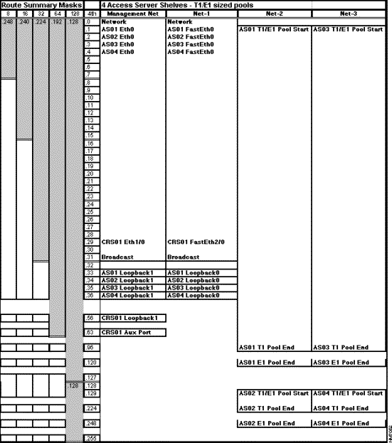
The Cisco IP addressing spreadsheet that follows (Figure 1) can help you set IP addresses for your AccessPath-LS3 system. Use the spreadsheet along with the following explanation to plan IP addressing for your AccessPath-LS3 system.


Note      The private network numbers shown in the sample configuration files later in this document use addresses assigned directly from the IP addressing spreadsheets. These exact addresses may be used for internal networks but should never be made available over the Internet.


Figure 1   IP Addressing Spreadsheet for a T1/E1 Network


Using the IP Addressing Spreadsheets

The columns in the IP addressing spreadsheet are used as follows:

Double lines, are used to assist with aligning subnet boundaries.

Ethernet and Fast Ethernet Broadcast Network Addresses

Each stack member's Ethernet and Fast Ethernet interfaces require an IP address assignment. Because Ethernet is broadcast, these IP assignments must come from a contiguous block that begins and ends at some power of 2 boundary. In addition, this block must be big enough to accommodate all possible interfaces in the biggest AccessPath configuration (21 Access Server Shelves).


Note      The addressing scheme was developed to accommodate the AccessPath system, which can have up to 21 Access Server Shelves. The spreadsheet shown in Figure 1 has been scaled down for the AccessPath-LS3 system, which can have up to 4 Access Server Shelves.


For the AccessPath System, a block of 32 addresses is needed, of which the first and last are not usable for IP assignments, so 30 usable IP addresses remain. The Ethernet group addresses are at the beginning of the management network, and the Fast Ethernet addresses are at the beginning of the first network (Net-1).

Access Server Address Pools

The remaining address space is required for the stack host-specific or 32-bit subnet addresses and could be anywhere on any network. They do not technically have to be contiguous; however, this addressing scheme tries to keep things uniform in order to simplify management and support.

The Loopback 0 interfaces need IP addresses, which are assigned in a block below the Fast Ethernet network addresses. Again, they do not have to be in a contiguous block, but we chose to do this to help reduce the number of routes.

Next, addresses are assigned to the Access Server Shelf pools. Pool assignments are kept within the defined 24-bit subnet addresses, starting and stopping on power of 2 boundaries. The resulting assignments allow for only 8 E1 interfaces per 24-bit subnet network. Because an Access Server Shelf can have a Quad E1 card, each pool should accommodate up to 120 addresses. This fits nicely in a 25-bit network, therefore each 24-bit subnet network would have 2 pools. In a T1 configuration, the pool consists of only 96 addresses in each range, but the ranges are the same, only 2 per 24-bit network. See the spreadsheet for details.

Optional Management/Failover Network Addresses

A block of 64 contiguous addresses is assigned as management or failover network addresses. The first 32 addresses comprise a 26-bit subnet which is used for the Ethernet (broadcast) interfaces inside the stack. The remaining IP numbers in this group are host-specific or 32-bit subnet addresses and are used for nonbroadcast interfaces for management traffic, such as Loopback 1 interfaces or AUX port peer IP assignments.

This group of management addresses is assigned based on the starting address. This starting address can take on any value in its first three octets but the fourth octet must be 0, 64, 128, or 192. The spreadsheet shows the group that starts at .0. If another value for the fourth octet is chosen, simply add it to the value indicated on the spreadsheet to arrive at the actual address. For example, starting at 64 would mean that the peer address for the Eth1/0 port on the Cisco 3640 would become xxx.xxx.xxx.93 (xxx.xxx.xxx.64 + xxx.xxx.xxx.29).


Note      The use of management/failover network addresses requires an additional 10-Mbps segment with a hub or switch.


Summary Masks

In order to minimize the number of data broadcasts with each routing update, we implemented summary address statements on each interface. Each pool is summarized as a 25-bit subnet network. For example, if you transcribe this into Cisco IOS configuration commands using an EIGRP process number of 4000 and a network address of 172.21.107.0, the command becomes:

ip summary-address eigrp 4000 172.21.107.0 255.255.255.128

This addressing scheme uses Variable Length Subnet Masking (VLSM) to conserve IP address space, and therefore limits our choice of internal routing protocols to those with VLSM support. OSPF, static routes, and IS-IS support variable-length subnet masks (VLSMs).

Booting the Console Router Shelf for the First Time

Each time you power on the router, it goes through the following boot sequence:

1. The router goes through power-on self-test diagnostics to verify basic operation of the CPU, memory, and interfaces.

2. The system bootstrap software executes and searches for a valid Cisco IOS image (router operating system software). The source of the Cisco IOS image (Flash memory or a Trivial File Transfer Protocol [TFTP] server) is determined by the configuration register setting. The factory-default setting for the configuration register is 0x2102, which indicates that the router should attempt to load a Cisco IOS image from Flash memory.

3. If after five attempts a valid Cisco IOS image is not found in Flash memory, the router reverts to boot ROM mode (which is used to install or upgrade a Cisco IOS image).

4. If a valid Cisco IOS image is found, then the router searches for a valid configuration file.

5. If a valid configuration file is not found in NVRAM, the router runs the System Configuration Dialog so you can configure it manually. For normal router operation, there must be a valid Cisco IOS image in Flash memory and a configuration file in NVRAM.

The first time you boot your router, you will need to configure the router interfaces and then save the configuration to a file in NVRAM. See the next section "Configuring the Console Router Shelf for the First Time" for interface configuration information. See the section "Saving Configuration Changes" later in this document for information on how to save the router configuration to NVRAM.

Configuring the Console Router Shelf for the First Time

You can configure the Console Router Shelf using one of the following procedures, which are described in this section:

This document instructs you to use the System Configuration Dialog and then the Configuration mode to configure the Console Router Shelf. You will then use the configuration mode to configure the Access Server Shelves.

Timesaver   Acquire the correct network addresses from your network plan before you begin to configure the router.

If you are not familiar with Cisco IOS software, refer to the Configuration Fundamentals Configuration Guide, which is on the Documentation CD-ROM, the web, or you can order the printed document for more information.

Using the System Configuration Dialog

If you do not plan to use AutoInstall, make sure all the WAN cables are disconnected from the router. The router will attempt to run AutoInstall whenever you power it on if there is a WAN connection on both ends and the router does not have a configuration file stored in NVRAM. It can take several minutes for the router to determine that AutoInstall is not connected to a remote Transmission Control Protocol/Internet Protocol (TCP/IP) host.

If your router does not have a configuration (setup) file and you are not using AutoInstall, the router will automatically start the setup command facility. An interactive dialog called the System Configuration Dialog appears on the console screen. This dialog helps you navigate through the configuration process by prompting you for the configuration information necessary for the router to operate.

Many prompts in the System Configuration Dialog include default answers, which are included in square brackets following the question. To accept a default answer, press Return; otherwise, enter your response.

This section gives an example configuration using the System Configuration Dialog. When you are configuring your router, respond as appropriate for your network.

At any time during the System Configuration Dialog, you can request help by typing a question mark (?) at a prompt.

Before proceeding with the System Configuration Dialog, obtain from your system administrator the node addresses and the number of bits in the subnet field (if applicable) of the router ports. For more information about IP addresses and subnets, refer to the Internetworking Technology Overview publication, which is on the documentation CD-ROM, the web, or you can order the printed document.


Note      You can run the Configuration Dialog any time you are at the privileged EXEC prompt (#) by entering the setup command.


Take the following steps to configure the router using the System Configuration Dialog:


Step 1   Connect a console terminal to the console port on the front panel of your Console Router Shelf, and then power ON the router.

(For more information, refer to the section "Connecting to the Console Port on the Console Router Shelf" in Cisco AccessPath-LS3 Integrated Access System Hardware Installation and Configuration document.

The default parameters for the console port are 9600 baud, 8 data bits, no parity, and 1 stop bits.

Step 2   After about 30 seconds, information similar to the following is displayed on the console screen.

The messages displayed vary, depending on the interfaces on the rear panel of the router and the Cisco IOS release and feature set you selected. The screen displays in this section are for reference only and may not exactly reflect the screen displays on your console.

System Bootstrap, Version X.X(X) [XXXXX XXX], RELEASE SOFTWARE
Copyright (c) 1994-199X by cisco Systems, Inc.
C3600 processor with 16384 Kbytes of main memory
Main memory is configured to 64 bit mode with parity disabled
program load complete, entry point: 0x80008000, size: 0x30277c
Self decompressing the image : #################################################
################################################################################
################################################################################
#################### [OK]
Restricted Rights Legend
Use, duplication, or disclosure by the Government is
subject to restrictions as set forth in subparagraph
(c) of the Commercial Computer Software - Restricted
Rights clause at FAR sec. 52.227-19 and subparagraph
(c) (1) (ii) of the Rights in Technical Data and Computer
Software clause at DFARS sec. 252.227-7013.
Cisco Systems, Inc.
170 West Tasman Drive
San Jose, California 95134-1706
Cisco Internetwork Operating System Software
IOS (tm) 3600 Software (XXXX-X-X), Version XX.X (XXX)_[XXXX XXX]
Copyright (c) 1986-199X by cisco Systems, Inc.
Compiled Mon 01-Jul-9X 21:38 by XXXXX
Image text-base: 0x60008890, data-base: 0x605CA000
cisco 3640 (R4700) processor (revision 0x00) with 12288K/4096K bytes of memory.
Processor board ID 00000000
R4700 processor, Implementation XX, Revision X.X
Bridging software.
SuperLAT software copyright 1990 by Meridian Technology Corp).
X.25 software, Version 2.0, NET2, BFE and GOSIP compliant.
TN3270 Emulation software (copyright 1994 by TGV Inc).
2 Ethernet/IEEE 802.3 interface.
2 Serial network interface(s).
DRAM configuration is 64 bits wide with parity disabled.
125K bytes of non-volatile configuration memory.
4096K bytes of processor board System flash (Read/Write)
Notice: NVRAM invalid, possibly due to write erase.
--- System Configuration Dialog ---
At any point you may enter a question mark '?' for help.
Use ctrl-c to abort configuration dialog at any prompt.
Default settings are in square brackets '[]'.
Would you like to enter the initial configuration dialog? [yes]:

Step 3   Press Return or enter yes to begin the configuration process.

Step 4   When the System Configuration Dialog asks whether you want to view the current configuration, press Return to accept the default entry (yes) in square brackets:

First, would you like to see the current interface summary? [yes]:
Any interface listed with OK? value "NO" does not have a valid configuration
Interface IP-Address OK? Method Status Protocol
Ethernet1/0 unassigned NO unset up down
Serial1/0 unassigned NO unset down down
Ethernet1/1 unassigned NO unset up down

Step 5   Configure the host name.

Enter host name [Router]: CRS01

Step 6   Enter an enable secret password:

The enable secret is a one-way cryptographic secret password used instead of the enable password when it exists.
Enter enable secret: secret123
The enable password is used when there is no enable secret password and when using older software and some boot images.

The enable password is used when the enable secret password does not exist. For maximum security, be sure the passwords are different. If you enter the same password for both, the router will accept your entry, but will display a warning message indicating that you should enter a different password.

Step 7   Enter the enable and virtual terminal passwords:

Enter enable password: cisco
Enter virtual terminal password: vterm1

Step 8   Press Return to accept Simple Network Management Protocol (SNMP) management, or enter no to refuse it:

Configure SNMP Network Management? [yes]: no

Step 9   In the following example, the router is configured for Internet Protocol (IP). Configure the appropriate protocols for your router using the example configuration that follows:

Configure LAT? [no]:
Configure AppleTalk? [no]:
Configure DECnet? [no]:
Configure IP? [yes]: yes
Configure IGRP routing? [yes]: no
Configure RIP routing? [no]:
Configure CLNS? [no]:
Configure IPX? [no]:
Configure Vines? [no]:
Configure XNS? [no]:
Configure Apollo? [no]:
Configure bridging? [no]:
Configure Async lines? [yes]: no

Configuring Ethernet Interfaces

The Ethernet interfaces are configured to allow connection to a LAN. To configure the interface parameters, you need to know the Ethernet interface network addresses.

Take the following steps to configure an Ethernet interface to allow communication over a LAN:


Step 1   Press Return or enter yes to configure the LAN interface:

Configuring interface parameters:
Configuring interface Ethernet1/0:
Is this interface in use? [yes]:

Step 2   Determine which protocols you want to support on the LAN interface and enter the appropriate responses. In the following example, the system is being configured for IP:

Configure IP on this interface? [yes]:
IP address for this interface: 172.21.105.29
Number of bits in subnet field [8]: 11
Class B network is 172.21.0.0, 11 subnet bits; mask is /27

Step 3   If there is more than one LAN interface on your router, repeat this procedure to configure the second and subsequent LAN interfaces.

Configuring the Fast Ethernet Interface

The Fast Ethernet interface is configured to allow connection to a 100BaseT LAN. To configure the interface parameters, you need to know the Fast Ethernet interface network addresses.

Take the following steps to configure a Fast Ethernet interface to allow communication over a LAN:


Step 1   Press Return or enter yes to configure the LAN interface:

Configuring interface FastEth2/0:
Is this interface in use? [yes]:

Step 2   Determine which protocols you want on the LAN interface and enter the appropriate responses. (You must have previously enabled these protocols as part of global configuration.) In the following example, the interface is being configured for IP:

Configure IP on this interface? [yes]:
IP address for this interface: 172.21.106.29
Number of bits in subnet field [8]: 11
Class B network is 172.21.106.29, 11 subnet bits; mask is /27

Step 3   If there is more than one LAN interface on your router, repeat this procedure to configure the second and subsequent LAN interfaces.

Configuring Serial Interfaces

The serial interfaces are configured to allow connection to WANs through a CSU/DSU. All serial ports are initially configured as synchronous ports. After the initial configuration is completed, configure the serial ports you plan to use as asynchronous ports using the physical-layer command in configuration mode.

Take the following steps to configure the serial port(s):


Step 1   Press Return or enter yes to configure serial port 0 in slot 1:

Configuring interface Serial1/0:
Is this interface in use? [yes]:

Step 2   Determine which protocols you want on the synchronous serial interface and enter the appropriate responses. In the following example, the system is being configured for IP:

Configure IP on this interface? [yes]:
Configure IP unnumbered on this interface? [no]:
IP address for this interface: 192.200.200.1
Number of bits in subnet field [0]:
Class B network is 192.200.200.1, 0 subnet bits; mask is /24

Step 3   If there is more than one serial interface on your router, repeat this procedure to configure the remaining serial interfaces.

Step 4   The configuration you entered is now displayed and you are asked if you want to use the displayed configuration. If you enter no, you will lose the configuration information you just entered and you can begin the configuration again. If you enter yes, the configuration will be entered and saved in the startup configuration:

Use this configuration? [yes/no]: yes
Building configuration...
Use the enabled mode 'configure' command to modify this configuration.
Press RETURN to get started!

You have now entered a basic configuration. You will use the command-line interface to enter the rest of the configuration file for the Console Router Shelf. Proceed to the next section for additional configuration instructions.

Additional Console Router Shelf Configuration Tasks

The asynchronous ports, logging, security, and aux port configurations still need to be set using the command-line interface.

The following steps provide an example of how to complete the configuration of the Router Shelf.


Step 1   Enter the config terminal command to enter configuration mode:

CRS01> enable
Password:
CRS01# config terminal
CRS01(config)#

The router enters global configuration mode, indicated by the CRS01(config)# prompt.

Step 2   Enter commands so that the resulting configuration file is similar to the one shown below. The user-defined parameters are shown in bold.

Timesaver   Use the Tab to perform command completion and use the ? to see the command options.

no service finger
service timestamps debug datetime msec localtime show-timezone
service timestamps log datetime msec localtime show-timezone
!Put timestamps on the debugging and log messages, using localtime as set
!with the clock timezone command.
service password-encryption !Turn on encryption of the passwords.
no service udp-small-servers
no service tcp-small-servers !Disables a variety of services that can be
!exploited to cause service interruptions.
!
no service config !Disables automatic loading of config files from
!a network server.
hostname CRS01 !Shown for reference only, this is already configured.
!
!The following aaa commands are only used if you have a TACACS or RADIUS !server. This example shows RADIUS, the TACACS commands are similar.
aaa new-model
aaa authentication login CONSOLE none !aaa commands are case-sensitive
aaa authentication login ADMIN radius local
aaa authentication login USERS radius
aaa authentication ppp USERS&TUNNELS if-needed radius
radius-server host 172.22.23.47 auth-port 1645 acct-port 1646
radius-server key bananas
!
aaa authentication ppp ADMIN if-needed radius local
aaa authorization network radius if-authenticated
aaa accounting network start-stop radius
aaa accounting connection start-stop radius
aaa accounting exec start-stop radius
!
enable secret secret123 !Defines the password needed to enter
!enable mode.
enable password cisco
!
username justincase password doublesecret !The basic level username and password.
!
ip subnet-zero
no ip source-route !Enables the use of subnet zero for
!addressing to provide for additional
!addressing space
!For APM support only uncomment the following line
!ip rcmd rcp-enable !Enables host users to copy to and from
!the router.
!ip rcmd remote-username APMadmin !Validates remote users for remote copy.
ip name-server 172.22.5.253 172.22.5.254 !Address of your DNS server.
ip radius source-interface Loopback1 !Only use with RADIUS.
clock timezone GMT 0 !Set the system clock to timezone GMT
!with no offset. This timestamp is
!used for debug and log messages.
interface Loopback 1 !Specifies which interface is being
!configured.
description "Management SNMP AAA pseudo interface"
ip address 172.21.105.56 255.255.255.255 !Use the assigned host numbers
!from the spreadsheet with your
!own network value.
!
interface Ethernet1/0
description "Optional management and failover path"
ip address 172.21.105.29 255.255.255.224 !Address of management network.
no ip mroute-cache
no shutdown !Enables the Ethernet interface.
!
interface Ethernet1/1
description "Corp Net"
ip address 172.22.16.218 255.255.255.224 !Address of the "Corp Net" network.
no ip mroute-cache
no shutdown
!
interface Serial1/0
description "Data Backhaul"
ip address 192.200.200.1 255.255.255.0
!
interface FastEthernet2/0
description "To AS via FastHub"
ip address 172.21.106.29 255.255.255.224
no ip mroute-cache
!
!The following lines allow you to connect a modem to the AUX port.
!Uncomment them if you attach a modem to this device.
!interface Async 129
!description "OSS Modem Incoming Call"
!ip unnumbered Loopback1 !Use IP address of loopback interface.
!Allows a virtual IP address to be used on
!the ASYNC interface, which saves on
!address space.
!encapsulation ppp
!no ip mroute-cache
!async dynamic address
!async mode interactive
!peer default ip address 172.21.105.63
!no cdp enable
!no fair-queue
!ppp authentication chap callin ADMIN
!dialer-group 1 !Places Async 129 into dialer group 1. See
!dialer commands later in this config.
!
router eigrp 4000
redistribute connected
redistribute static !Set static route for all devices in stack.
passive-interface Ethernet1/1 !Keep routes from propagating to Corp Net.
passive-interface Serial1/0
network 192.200.200.0
network 172.21.0.0
network 172.22.0.0
no auto-summary
!
ip classless
ip route 0.0.0.0 0.0.0.0 172.22.16.193 !Address of Ethernet next hop router.
logging trap debugging
logging facility local7 !Writes syslog messages to local7
!facility on the loghost.
logging 172.22.23.47 !Address of network management station.
no access-list 10
access-list 10 permit 172.22.23.47 !Address of network management station.
!
snmp-server community public RO
snmp-server community private RW 10 !Access list 10 is defined above to
!permit NMS read/write SNMP commands.
snmp-server trap-source Loopback1
snmp-server location "NOC Center"
snmp-server contact "Network Administrator"
snmp-server system-shutdown
snmp-server host 172.22.23.47 CRS01 !Address of net mgt station, and trap
!community string (hostname).
dialer-list 1 protocol ip permit
!
line con 0
session-timeout 45
exec-timeout 45 0
login authentication CONSOLE !Console connections use no password
!and exec enable mode requires the
!secret password.
transport preferred none !Will not try to telnet on bad command.
!
!Uncomment the following lines if you have the 16-port asynchronous module
!installed in the Cisco 3640 router.
!line 1 16
!session-timeout 60
!no exec
!login authentication ADMIN
!modem InOut
!transport input all
!flowcontrol hardware
!The following interface is set to use a modem on the AUX port.
line aux 0
exec-timeout 15 0
autoselect during-login
autoselect ppp
login authentication ADMIN
modem InOut
transport preferred none
transport input all
speed 115200
flowcontrol hardware
line vty 0 4
session-timeout 45
exec-timeout 45 0
password cisco
login authentication ADMIN
!
ntp server 172.22.23.47 !Points to an NTP if available.
ntp source loopback 1

Step 3   After you complete the configuration, press Ctrl-z to exit configuration mode.

Step 4   Write the new configuration to memory, as follows:

CRS01# copy running-config startup-config

The system displays a confirmation message when the configuration is saved.

Step 5   Enter the disable command to return to the user level:

CRS01# disable
CRS01>

Step 6   Enter the show commands to check the configuration.

For more information about configuring the Console Router Shelf, refer to the Cisco 3640 Router Installation and Configuration Guide. If you need assistance, see the last section "Cisco Connection Online."

Configuring AccessPath-LS3 Components from a TFTP Server

Your AccessPath-LS3 system comes with a CD that contains sample configuration files for each of the AccessPath-LS3 components. You can copy these files to your TFTP server, edit them using a text editor and the configurations in the following sections as examples, and download them to each component using TFTP.


Note      This solution requires that the AccessPath-LS3 system have a functional connection to a network with a TFTP server.


To copy a configuration file from a TFTP server to NVRAM, perform the following steps (example uses a Cisco 3640):


Step 1   Enter the copy tftp startup-config command without the destination partition and destination filename options specified in the initial command line:

Router# copy tftp startup-config

Step 2   Enter or confirm the IP address of the remote TFTP server.

Address of remote host [255.255.255.255]? 171.69.91.126

Step 3   Specify the source filename. In this example, the UNIX filename crs01-confg is entered to copy the crs01-confg file:

Name of configuration file [router-confg]? crs01-confg
Configure using crs01-confg from 171.69.91.126? [confirm] y
Loading crs01-confg from 171.69.91.126 (via Ethernet1/0): !
[OK - 3147/128975 bytes]
[OK]
Router#
%SYS-5-CONFIG_NV: Non-volatile store configured from crs01-confg by console
tftp from 171.69.91.126

Step 4   Review the configuration to insure it is really what you want to load.

Router# show startup-config

The router displays the configuration loaded from the TFTP server and should look like the sample configuration on page 10.

Step 5   Reload the router, as follows:

Router# reload
Proceed with reload? [confirm] y
*Feb 28 16:00:46.507 PST: %SYS-5-RELOAD: Reload requested

The router displays the reload messages. Watch for error messages during the configuration load. The reload is done over a copy to prevent the configurations from merging. This ensures a clean reload and configuration.

Step 6   Repeat this procedure for each AccessPath-LS3 device.

Configuring the Access Server Shelves

This section describes how to connect to an Access Server Shelf, substitute your own IP addresses for the placeholder addresses in the configuration file, and configure interfaces. The instructions describe connecting to the console port on each Access Server Shelf using a Telnet connection through the Console Router Shelf. This is only possible if have the 16-port asynchronous module installed in the Console Router Shelf. If you do not have this module, you must connect a console to the console port on each Access Server, refer to the Cisco AS5300 Universal Access Server Hardware Installation Guide for detailed instructions.

This section also includes a sample configuration for each Access Server Shelf.


Step 1   Telnet to the Console Router Shelf and connect to the first Access Server Shelf, be sure that the Access Server Shelf is not powered on.

In the following example the Console Router Shelf, at IP address 172.21.105.56, connects to the Access Server Shelf AS01 on port 2001:

# telnet 172.21.105.56 2001
Trying 172.21.105.56...
Connected to 172.21.105.56.
Escape character is '^]'.

Step 2   Turn on the Access Server Shelf.

The access server automatically goes into setup mode. Type Ctrl-c to quit setup mode so you can manually enter the configuration.

Step 3   Enter enable mode.

In the following example, the user enters enable mode (without entering a password, because none is set yet).

router> enable
router#

Step 4   Write the Access Server Shelf configuration to the terminal to view it (and for reference when configuring IP addresses).

AS01# show running-config
Current configuration:
!
version 11.2
service timestamps debug datetime msec localtime show-timezone
service timestamps log datetime localtime show-timezone
service udp-small-servers
service tcp-small-servers
!
...

Step 5   Enter global configuration mode and enter the hostname, the IP address, and subnet mask for interface Ethernet 0, and enter exit.

router# configure term
router(config)# hostname AS01
AS01(config)# interface fastethernet 0
AS01(config-if)# ip address 172.21.106.1 255.255.255.224
!Use an address from Net-1.
AS01(config-if)# exit
AS01(config)#

Configure each of the Access Server Shelves similarly. See the following sections for additional configuration details.


Note      The previous procedure does not cover all of the steps required for an Access Server Shelf configuration. For more information, refer to the Cisco AS5300 Universal Access Server Software Configuration Guide.


Sample Configuration for Access Server Shelf 01 (AS01)

Use the sample configuration below to configure AS01. You will have to Telnet to AS01 using port 2001 (if you have the 16-port asynchronous module installed in the Console Router Shelf) or you must connect a console to the console port on the access server. Enter the configuration mode as described in the previous section. The user-defined parameters are shown in bold.

This configuration is for a typical United States PRI/T1 installation.


Note      The sample configuration file for Access Server Shelf 01 contains additional comment lines beyond those shown in the other Access Server Shelf sample files. Refer to the AS01 example if you need a better understanding of the basic design of the Access Server Shelf configurations.


no service finger
service timestamps debug datetime msec localtime show-timezone
service timestamps log datetime msec localtime show-timezone
!Put timestamps on the debugging and log messages, using localtime as set
!with the clock timezone command.
service password-encryption !Turn on encryption of the passwords.
no service udp-small-servers
no service tcp-small-servers !Disables a variety of services that can be
!exploited to cause service interruptions.
!
no service config !Disables automatic loading of config files from
!a network server.
!
hostname AS01
!
!Use the following commands only if you have a TACACS or RADIUS server.
aaa new-model
aaa authentication login CONSOLE none
aaa authentication login ADMIN radius local
aaa authentication login USERS radius
aaa authentication ppp USERS&TUNNELS if-needed radius
aaa authorization network radius if-authenticated
aaa accounting network start-stop radius
aaa accounting connection start-stop radius
aaa accounting exec start-stop radius
radius-server host 172.22.23.47 auth-port 1645 acct-port 1646
radius-server key bananas
enable secret secret123
enable password cisco
!
username stack1 password secret !The SGBP username and password needs
!to be the same for all access servers
!in the stack and must match the SGBP
!group name.
username justincase password doublesecret
ip subnet-zero !Enables the use of subnet zero for
!addressig to provide additional
!addressing space
no ip source-route !Prevents the router from accepting TCP
!packets with a modified source-route.
ip name-server 172.22.5.253 172.22.5.254
ip radius source-interface Loopback1
!
sgbp group stack1
sgbp member AS02 172.21.106.34 !106 subnet represents Net-1.
sgbp member AS03 172.21.106.35 !Loopback0 address of neighbor Access
!Servers.
sgbp member AS04 172.21.106.36
sgbp source-ip 172.21.106.33 !The Loopback0 interface.
async-bootp dns-server 172.22.5.253 172.22.5.254
isdn switch-type primary-5ess !Type of switch to which the ISDN lines
!are connected.
clock timezone GMT 0 !Set the system clock to timezone GMT with
!no offset. This is the timestamp used for
!debug and log messages.
!
controller T1 0
framing esf
fdl ansi
clock source line primary
linecode b8zs
pri-group timeslots 1-24
no shutdown
!
controller T1 1
framing esf
fdl ansi
clock source line secondary
linecode b8zs
pri-group timeslots 1-24
no shutdown
!
controller T1 2
framing esf
fdl ansi
clock source internal
linecode b8zs
pri-group timeslots 1-24
no shutdown
!
controller T1 3
framing esf
fdl ansi
clock source internal
linecode b8zs
pri-group timeslots 1-24
no shutdown
!
interface Loopback0 !Specifies the interface being configured.
description "L2F tunnel AS01 pseudo interface"
ip address 172.21.106.33 255.255.255.255
!
interface Loopback1
description "Management SNMP AAA AS01 pseudo interface"
ip address 172.21.105.33 255.255.255.255
!The Ethernet0 interface is optional in this configuration.
!interface Ethernet0
!description "Optional management and failover path"
!ip address 172.21.105.1 255.255.255.224
!no ip directed-broadcast
!ip summary-address eigrp 4000 172.21.107.0 255.255.255.96
!The 107 subnet is the equivalent of Net-2 in the IP spreadsheet and !starts the range of the address pool. The 96 in the subnet mask ends !the range for a T1 connection, it would be 128 for E1.
!no shutdown !Enables the Ethernet interface.
!ip route-cache
!ip mroute-cache
!default keepalive
!no fair-queue
!
interface FastEthernet0
description "Primary Data Path"
ip address 172.21.106.1 255.255.255.224
no ip directed-broadcast
ip summary-address eigrp 4000 172.21.107.0 255.255.255.96
!The 107 subnet is the equivalent of Net-2 in the IP spreadsheet and !starts the range of the address pool. The 96 in the subnet mask ends !the range for a T1 connection, it would be 128 for E1.
no shutdown !Enables the Fast Ethernet interface.
ip route-cache
ip mroute-cache
default keepalive
no fair-queue
!
interface Serial0:23
description "PRI D channel for T1 0"
ip unnumbered Loopback0
encapsulation ppp
isdn incoming-voice modem !For PRI T1 only
peer default ip address pool poolAS01
dialer rotary-group 1
no ip mroute-cache
no fair-queue
no keepalive
no cdp enable
no shutdown
dialer-group 1
!
interface Serial1:23
description "PRI D channel for T1 1"
ip unnumbered Loopback0
encapsulation ppp
isdn incoming-voice modem !For PRI T1 only
peer default ip address pool poolAS01
dialer rotary-group 1
no fair-queue
no cdp enable
no ip mroute-cache
no keepalive
no shutdown
dialer-group 1
!
interface Serial2:23
description "PRI D channel for T1 2"
ip unnumbered Loopback0
encapsulation ppp
isdn incoming-voice modem !For PRI T1 only
peer default ip address pool poolAS01
dialer rotary-group 1
no ip mroute-cache
no fair-queue
no cdp enable
no keepalive
no shutdown
dialer-group 1
!
interface Serial3:23
description "PRI D channel for T1 3"
ip unnumbered Loopback0
encapsulation ppp
isdn incoming-voice modem !For PRI T1 only
peer default ip address pool poolAS01
dialer rotary-group 1
no ip mroute-cache
no fair-queue
no cdp enable
no keepalive
no shutdown
dialer-group 1
!
interface Group-Async1
description "Async Incoming Modem Call"
ip unnumbered Loopback0
no ip mroute-cache
encapsulation ppp
async dynamic address
async mode interactive
no snmp trap link-status !Suppress link-up and link-down messages
!to the network management station for all
!modem calls.
peer default ip address pool poolAS01
ip tcp header-compression passive !Enables header compression only if both
!sides of the link support it.
default keepalive
no fair-queue
no cdp enable
ppp authentication chap callin USERS&TUNNELS
ppp chap hostname whatremotesees
group-range 1 96 !Range should match the number of
!modems, can be 96 for T1 or 120
!for E1.
!
interface Dialer1
ip unnumbered Loopback0
encapsulation ppp
no snmp trap link-status !Suppress link-up and link-down messages
!to the network management station for all
!ISDN calls.
no keepalive
peer default ip address pool poolAS01
ppp multilink !Enables Multichannel PPP
ppp authentication chap callin USERS&TUNNELS
ppp chap hostname whatremotesees
dialer-group 1
dialer in-band
no fair-queue
no cdp enable
!
router eigrp 4000
redistribute connected
passive-interface Loopback0
passive-interface Loopback1
passive-interface Serial0:23
passive-interface Serial1:23
passive-interface Serial2:23
passive-interface Serial3:23
network 172.21.0.0
no auto-summary
!
ip local pool poolAS01 172.21.107.1 172.21.107.96 !These addresses should !be from a registered network if you want users to have access to !anything beyond the local domain boundary.
ip classless
!
logging trap debugging
logging facility local7 !Write syslog messages to local7 facility
!on the loghost.
logging 172.22.23.47
!
!The following commands are only used for network management.
snmp-server community public RO
snmp-server community private RW 10
snmp-server trap-source Loopback1
snmp-server host 172.22.23.47 AS01
snmp-server location "NOC Center"
snmp-server contact "Network Administrator"
snmp-server system-shutdown
access-list 10 permit 172.22.23.47
!
dialer-list 1 protocol ip permit !Permits IP for all interfaces using the
! !Dialer1 interface settings.
line con 0
session-timeout 30
exec-timeout 15 0
logout-warning 60
login authentication CONSOLE
line 1 96 !Range should match the number of modems.
autoselect during-login
autoselect ppp
login authentication USERS
modem InOut
transport preferred none
line aux 0
line vty 0 4
session-timeout 45
exec-timeout 45 0
login authentication ADMIN
!
ntp server 172.21.105.56 !Loopback1 address of Cisco 3640.
end

Sample Configuration for Access Server Shelf 02 (AS02)

Use the sample configuration below to configure AS02. You will have to Telnet to AS02 using port 2002 (if you have the 16-port asynchronous module installed in the Console Router Shelf) or you must connect a console to the console port on the access server. Enter the configuration mode as described in the section, "Configuring the Access Server Shelves." The user-defined parameters are shown in bold.

This configuration is for a typical United States PRI/T1 installation.

no service finger
service timestamps debug datetime msec localtime show-timezone
service timestamps log datetime msec localtime show-timezone
service password-encryption
no service udp-small-servers
no service tcp-small-servers
!
hostname AS02
!
!Use the following commands only if you have a TACACS or RADIUS server.
aaa new-model
aaa authentication login CONSOLE none
aaa authentication login ADMIN radius local
aaa authentication login USERS radius
aaa authentication ppp USERS&TUNNELS if-needed radius
aaa authorization network radius if-authenticated
aaa accounting network start-stop radius
aaa accounting connection start-stop radius
aaa accounting exec start-stop radius
radius-server host 172.22.23.47 auth-port 1645 acct-port 1646
radius-server key bananas
!
enable secret secret123
enable password cisco
!
username stack1 password secret
username justincase password doublesecret
ip subnet-zero
no ip source-route
ip name-server 172.22.5.253 172.22.5.254
!
sgbp group stack1
sgbp member AS01 172.21.106.33 !106 address represents Net-1.
sgbp member AS03 172.21.106.35 !Loopback0 address of neighbor
sgbp member AS04 172.21.106.36 !Access Servers.
sgbp source-ip 172.21.106.34 !This is the Loopback0 interface.
async-bootp dns-server 172.22.5.253 172.22.5.254
isdn switch-type primary-5ess
clock timezone GMT 0
!
controller T1 0
framing esf
fdl ansi
clock source line primary
linecode b8zs
pri-group timeslots 1-24
no shutdown
!
controller T1 1
framing esf
fdl ansi
clock source line secondary
linecode b8zs
pri-group timeslots 1-24
no shutdown
!
controller T1 2
framing esf
fdl ansi
clock source internal
linecode b8zs
pri-group timeslots 1-24
no shutdown
!
controller T1 3
framing esf
fdl ansi
clock source internal
linecode b8zs
pri-group timeslots 1-24
no shutdown
!
interface Loopback0
description "L2F tunnel AS02 pseudo interface"
ip address 172.21.106.34 255.255.255.255
!
interface Loopback1
description "Management SNMP AAA AS02 pseudo interface"
ip address 172.21.105.34 255.255.255.255
!
!interface Ethernet0
!description "Optional management and failover path"
!ip address 172.21.105.2 255.255.255.224
!ip summary-address eigrp 4000 172.21.107.128 255.255.255.96
!The 107 subnet is the equivalent of Net-2 in the IP spreadsheet and !starts the range of the address pool. The 96 in the subnet mask ends the !range for an T1 connection, it would be 128 for E1.
!no ip directed-broadcast
!no shutdown
!ip route-cache
!ip mroute-cache
!default keepalive
!no fair-queue
!
interface FastEthernet0
description "Primary Data Path"
ip address 172.21.106.2 255.255.255.224
ip summary-address eigrp 4000 172.21.107.128 255.255.255.96
!The 107 subnet is the equivalent of Net-2 in the IP spreadsheet and !starts the range of the address pool. The 96 in the subnet mask ends the !range for an T1 connection, it would be 128 for E1.
speed auto
no shutdown
ip route-cache
ip mroute-cache
default keepalive
no fair-queue
!
interface Serial0:23
description "PRI D channel for T1 0"
ip unnumbered Loopback0
encapsulation ppp
isdn incoming-voice modem !For PRI T1 only
peer default ip address pool poolAS02
dialer rotary-group 1
no ip mroute-cache
no fair-queue
no cdp enable
no keepalive
no shutdown
dialer-group 1
!
interface Serial1:23
description "PRI D channel for T1 1"
ip unnumbered Loopback0
encapsulation ppp
isdn incoming-voice modem !For PRI T1 only
peer default ip address pool poolAS02
dialer rotary-group 1
no fair-queue
no cdp enable
no ip mroute-cache
no keepalive
no shutdown
dialer-group 1
!
interface Serial2:23
description "PRI D channel for T1 2"
ip unnumbered Loopback0
encapsulation ppp
isdn incoming-voice modem !For PRI T1 only
peer default ip address pool poolAS02
dialer rotary-group 1
no ip mroute-cache
no fair-queue
no cdp enable
no keepalive
no shutdown
dialer-group 1
!
interface Serial3:23
description "PRI D channel for T1 3"
ip unnumbered Loopback0
encapsulation ppp
isdn incoming-voice modem !For PRI T1 only
peer default ip address pool poolAS02
dialer rotary-group 1
no ip mroute-cache
no fair-queue
no cdp enable
no keepalive
no shutdown
dialer-group 1
!
interface Group-Async1
description "Async Incoming Modem Call"
ip unnumbered Loopback0
no ip mroute-cache
encapsulation ppp
async dynamic address
async mode interactive
no snmp trap link-status
peer default ip address pool poolAS02
ip tcp header-compression passive
default keepalive
no fair-queue
no cdp enable
ppp authentication chap callin USERS&TUNNELS
ppp chap hostname whatremotesees
group-range 1 96 !Range should match the number of
!modems, can be 96 for T1 or 120
!for E1.
!
interface Dialer1
ip unnumbered Loopback0
encapsulation ppp
no keepalive
peer default ip address pool poolAS02
ppp multilink !Enables Multichannel PPP
ppp authentication chap callin USERS&TUNNELS
ppp chap hostname whatremotesees
dialer-group 1
dialer in-band
no fair-queue
no cdp enable
!
router eigrp 4000
redistribute connected
passive-interface Loopback0
passive-interface Loopback1
passive-interface Serial0:23
passive-interface Serial1:23
passive-interface Serial2:23
passive-interface Serial3:23
network 172.21.0.0
no auto-summary
!
ip local pool poolAS02 172.21.107.129 172.21.107.224 !These addresses should !be from a registered network if you want users to have access to !anything beyond the local domain boundary.
ip classless
!
logging trap debugging
logging facility local7
logging 172.22.23.47
access-list 10 permit 172.22.23.47
!
!The following commands are only used for network management.
snmp-server community public RO
snmp-server community private RW 10
snmp-server trap-source Loopback1
snmp-server host 172.22.23.47 AS01
snmp-server location "NOC Center"
snmp-server contact "Network Administrato"
snmp-server system-shutdown
!
dialer-list 1 protocol ip permit
!
line con 0
session-timeout 30
exec-timeout 15 0
logout-warning 60
login authentication CONSOLE
!
line 1 96 !Range should match the number of modems.
autoselect during-login
autoselect ppp
login authentication USERS
modem InOut
transport preferred none
line aux 0
line vty 0 4
session-timeout 45
exec-timeout 45 0
login authentication ADMIN
!
ntp server 172.21.105.56 !Loopback1 address of Cisco 3640.
end

Sample Configuration for Access Server Shelf 03 (AS03)

Use the sample configuration below to configure AS03. You will have to Telnet to AS03 using port 2003 (if you have the 16-port asynchronous module installed in the Console Router Shelf) or you must connect a console to the console port on the access server. Enter the configuration mode as described in the section, "Configuring the Access Server Shelves." The user-defined parameters are shown in bold.

This configuration is for a typical United States PRI/T1 installation.

no service finger
service timestamps debug datetime msec localtime show-timezone
service timestamps log datetime msec localtime show-timezone
service password-encryption
no service udp-small-servers
no service tcp-small-servers
!
hostname AS03
!
!Use the following commands only if you have a TACACS or RADIUS server.
aaa new-model
aaa authentication login CONSOLE none
aaa authentication login ADMIN radius local
aaa authentication login USERS radius
aaa authentication ppp USERS&TUNNELS if-needed radius
aaa authorization network radius if-authenticated
aaa accounting network start-stop radius
aaa accounting connection start-stop radius
aaa accounting exec start-stop radius
radius-server host 172.22.23.47 auth-port 1645 acct-port 1646
radius-server key bananas
!
enable secret secret123
enable password cisco
!
username stack1 password secret
username justincase password doublesecret
ip subnet-zero
no ip source-route
ip name-server 172.22.5.253 172.22.5.254
ip radius source-interface Loopback1
!
sgbp group stack1
sgbp member AS01 172.21.106.33 !106 address represents Net-1.
sgbp member AS02 172.21.106.34 !Loopback0 address of neighbor
sgbp member AS04 172.21.106.36 !Access Servers.
sgbp source-ip 172.21.106.35 !This is the loopback0 interface
async-bootp dns-server 172.22.5.253 172.22.5.254
isdn switch-type primary-5ess
clock timezone GMT 0
!
controller T1 0
framing esf
fdl ansi
clock source line primary
linecode b8zs
pri-group timeslots 1-24
no shutdown
!
controller T1 1
framing esf
fdl ansi
clock source line secondary
linecode b8zs
pri-group timeslots 1-24
no shutdown
!
controller T1 2
framing esf
fdl ansi
clock source line primary
linecode b8zs
pri-group timeslots 1-24
no shutdown
!
controller T1 3
framing esf
fdl ansi
clock source internal
linecode b8zs
pri-group timeslots 1-24
no shutdown
!
interface Loopback0
description "L2F tunnel AS03 pseudo interface"
ip address 172.21.106.35 255.255.255.255
!
interface Loopback1
description "Management SNMP AAA AS03 pseudo interface"
ip address 172.21.105.35 255.255.255.255
!
!interface Ethernet0
!description "Optional management and failover path"
!ip address 172.21.105.3 255.255.255.224
!ip summary-address eigrp 4000 172.21.108.0 255.255.255.96
!The 108 subnet is the equivalent of Net-3 in the IP spreadsheet and !starts the range of the address pool. The 96 in the subnet mask ends !the range for an T1 connection, it would be 128 for E1.
!no ip directed-broadcast
!no shutdown
!ip route-cache
!ip mroute-cache
!default keepalive
!no fair-queue
!
interface FastEthernet0
description "Primary Data Path"
ip address 172.21.106.3 255.255.255.224
no ip directed-broadcast
ip summary-address eigrp 4000 172.21.108.0 255.255.255.96
!The 108 subnet is the equivalent of Net-3 in the IP spreadsheet and !starts the range of the address pool. The 96 in the subnet mask ends !the range for an T1 connection, it would be 128 for E1.
speed auto
no shutdown
ip route-cache
ip mroute-cache
default keepalive
no fair-queue
!
interface Serial0:23
description "PRI D channel for T1 0"
ip unnumbered Loopback0
encapsulation ppp
isdn incoming-voice modem !For PRI T1 only
peer default ip address pool poolAS03
dialer rotary-group 1
no fair-queue
no cdp enable
no keepalive
no shutdown
dialer-group 1
!
interface Serial1:23
description "PRI D channel for T1 1"
ip unnumbered Loopback0
encapsulation ppp
isdn incoming-voice modem !For PRI T1 only
peer default ip address pool poolAS03
dialer rotary-group 1
no fair-queue
no cdp enable
no ip mroute-cache
no keepalive
no shutdown
dialer-group 1
!
interface Serial2:23
description "PRI D channel for T1 2"
ip unnumbered Loopback0
encapsulation ppp
isdn incoming-voice modem !For PRI T1 only
peer default ip address pool poolAS03
dialer rotary-group 1
no ip mroute-cache
no fair-queue
no cdp enable
no keepalive
no shutdown
dialer-group 1
!
interface Serial3:23
description "PRI D channel for T1 3"
ip unnumbered Loopback0
encapsulation ppp
isdn incoming-voice modem !For PRI T1 only
peer default ip address pool poolAS03
dialer rotary-group 1
no ip mroute-cache
no fair-queue
no cdp enable
no keepalive
no shutdown
dialer-group 1
!
interface Group-Async1
description "Async Incoming Modem Call"
ip unnumbered Loopback0
no ip mroute-cache
encapsulation ppp
async dynamic address
async mode interactive
no snmp trap link-status
peer default ip address pool poolAS03
ip tcp header-compression passive
no fair-queue
no cdp enable
ppp authentication chap callin USERS&TUNNELS
ppp chap hostname whatremotesees
group-range 1 96 !Range should match the number of
!modems, can be 96 for T1 or 120
!for E1.
!
interface Dialer1
ip unnumbered Loopback0
encapsulation ppp
peer default ip address pool poolAS03
ppp multilink !Enables Multichannel PPP
ppp authentication chap callin USERS&TUNNELS
ppp chap hostname whatremotesees
dialer-group 1
dialer in-band
no fair-queue
no cdp enable
!
router eigrp 4000
redistribute connected
passive-interface Loopback0
passive-interface Loopback1
passive-interface Serial0:23
passive-interface Serial1:23
passive-interface Serial2:23
passive-interface Serial3:23
network 172.21.0.0
no auto-summary
!
ip local pool poolAS03 172.21.108.1 172.21.108.96 !These addresses should !be from a registered network if you want users to have access to !anything beyond the local domain boundary.
ip classless
!
logging trap debugging
logging facility local7
logging 172.22.23.47
access-list 10 permit 172.22.23.47
!
!The following commands are only used for network management.
snmp-server community public RO
snmp-server community private RW 10
snmp-server trap-source Loopback1
snmp-server host 172.22.23.47 AS03
snmp-server location "NOC Center"
snmp-server contact "Network Administrator"
snmp-server system-shutdown
!
dialer-list 1 protocol ip permit
!
line con 0
session-timeout 30
exec-timeout 15 0
logout-warning 60
login authentication CONSOLE
!
line 1 96 !Range should match the number of modems.
autoselect during-login
autoselect ppp
login authentication USERS
modem InOut
transport preferred none
line aux 0
line vty 0 4
session-timeout 45
exec-timeout 45 0
login authentication ADMIN
!
ntp server 172.21.105.56 !Loopback1 address of Cisco 3640.
end

Sample Configuration for Access Server Shelf 04 (AS04)

Use the sample configuration below to configure AS04. You will have to Telnet to AS04 using port 2004 (if you have the 16-port asynchronous module installed in the Console Router Shelf) or you must connect a console to the console port on the access server. Enter the configuration mode as described in the section, "Configuring the Access Server Shelves."

This configuration is for a typical United States PRI/T1 installation.

no service finger
service timestamps debug datetime msec localtime show-timezone
service timestamps log datetime msec localtime show-timezone
service password-encryption
no service udp-small-servers
no service tcp-small-servers
hostname AS04
!
!Use the following commands only if you have a TACACS or RADIUS server.
aaa new-model
aaa authentication login CONSOLE none
aaa authentication login ADMIN radius local
aaa authentication login USERS radius
aaa authentication ppp USERS&TUNNELS if-needed radius
aaa authorization network radius if-authenticated
aaa accounting network start-stop radius
aaa accounting connection start-stop radius
aaa accounting exec start-stop radius
radius-server host 172.22.23.47 auth-port 1645 acct-port 1646
radius-server key bananas
!
enable secret secret123
enable password cisco
!
username stack1 password secret
username justincase password doublesecret
ip subnet-zero
no ip source-route
ip name-server 172.22.5.253 172.22.5.254
ip radius source-interface Loopback1
!
sgbp group stack1
sgbp member AS02 172.21.106.34 !106 address represents Net-1.
sgbp member AS03 172.21.106.35 !Loopback0 address of neighbor
sgbp member AS01 172.21.106.33 !Access Servers.
sgbp source-ip 172.21.106.36 !This is the loopback0 interface
async-bootp dns-server 172.22.5.253 172.22.5.254
isdn switch-type primary-5ess
clock timezone GMT 0
!
controller T1 0
framing esf
fdl ansi
clock source line primary
linecode b8zs
pri-group timeslots 1-24
no shutdown
!
controller T1 1
framing esf
fdl ansi
clock source line secondary
linecode b8zs
pri-group timeslots 1-24
no shutdown
!
controller T1 2
framing esf
fdl ansi
clock source internal
linecode b8zs
pri-group timeslots 1-24
no shutdown
!
controller T1 3
framing esf
fdl ansi
clock source internal
linecode b8zs
pri-group timeslots 1-24
no shutdown
!
interface Loopback0
description "L2F tunnel AS04 pseudo interface"
ip address 172.21.106.36 255.255.255.255
!
interface Loopback1
description "Management SNMP AAA AS04 pseudo interface"
ip address 172.21.105.36 255.255.255.255
!
!interface Ethernet0
!description "Optional management and failover path"
!ip address 172.21.105.4 255.255.255.224
!ip summary-address eigrp 4000 172.21.108.128 255.255.255.96
!The 108 subnet is the equivalent of Net-3 in the IP spreadsheet and !starts the range of the address pool. The 96 in the subnet mask ends !the range for an T1 connection, it would be 128 for E1.
!no ip directed-broadcast
!no shutdown
!ip route-cache
!ip mroute-cache
!default keepalive
!no fair-queue
!
interface FastEthernet0
description "Primary Data Path"
ip address 172.21.106.4 255.255.255.224
ip summary-address eigrp 4000 172.21.108.128 255.255.255.96
!The 108 subnet is the equivalent of Net-3 in the IP spreadsheet and !starts the range of the address pool. The 96 in the subnet mask ends !the range for an T1 connection, it would be 128 for E1.
speed auto
no shutdown
ip route-cache
ip mroute-cache
default keepalive
no fair-queue
!
interface Serial0:23
description "PRI D channel for T1 0"
ip unnumbered Loopback0
encapsulation ppp
isdn incoming-voice modem !For PRI T1 only
peer default ip address pool poolAS04
dialer rotary-group 1
no fair-queue
no cdp enable
no keepalive
no shutdown
dialer-group 1
!
interface Serial1:23
description "PRI D channel for T1 1"
ip unnumbered Loopback0
encapsulation ppp
isdn incoming-voice modem !For PRI T1 only
peer default ip address pool poolAS04
dialer rotary-group 1
no fair-queue
no cdp enable
no ip mroute-cache
no keepalive
no shutdown
dialer-group 1
!
interface Serial2:23
description "PRI D channel for T1 2"
ip unnumbered Loopback0
encapsulation ppp
isdn incoming-voice modem !For PRI T1 only
peer default ip address pool poolAS04
dialer rotary-group 1
no ip mroute-cache
no fair-queue
no cdp enable
no keepalive
no shutdown
dialer-group 1
!
interface Serial3:23
description "PRI D channel for T1 3"
ip unnumbered Loopback0
encapsulation ppp
isdn incoming-voice modem !For PRI T1 only
peer default ip address pool poolAS04
dialer rotary-group 1
no ip mroute-cache
no fair-queue
no cdp enable
no keepalive
no shutdown
dialer-group 1
!
interface Group-Async1
description "Async Incoming Modem Call"
ip unnumbered Loopback0
no ip mroute-cache
encapsulation ppp
async dynamic address
async mode interactive
no snmp trap link-status
peer default ip address pool poolAS04
ip tcp header-compression passive
default keepalive
no fair-queue
no cdp enable
ppp authentication chap callin USERS&TUNNELS
ppp chap hostname whatremotesees
group-range 1 96 !Range should match the number of
!modems, can be 96 for T1 or 120
!for E1.
!
interface Dialer1
ip unnumbered Loopback0
encapsulation ppp
no keepalive
peer default ip address pool poolAS04
ppp multilink !Enables Multichannel PPP
ppp authentication chap callin USERS&TUNNELS
ppp chap hostname whatremotesees
dialer-group 1
dialer in-band
no fair-queue
no cdp enable
!
router eigrp 4000
redistribute connected
passive-interface Loopback0
passive-interface Loopback1
passive-interface Serial0:23
passive-interface Serial1:23
passive-interface Serial2:23
passive-interface Serial3:23
network 172.21.0.0
no auto-summary
!
ip local pool poolAS04 172.21.108.129 172.21.108.224 !These addresses should !be from a registered network for access beyond the local domain !boundary.
ip classless
no logging buffered
logging trap debugging
logging facility local7
logging 172.22.23.47
access-list 10 permit 172.22.23.47
!
!The following commands are only used for network management.
snmp-server community public RO
snmp-server community private RW 10
snmp-server trap-source Loopback1
snmp-server host 172.22.23.47 AS03
snmp-server location "NOC Center"
snmp-server contact "Network Administrator"
snmp-server system-shutdown
!
dialer-list 1 protocol ip permit
!
line con 0
session-timeout 30
exec-timeout 15 0
logout-warning 60
login authentication CONSOLE
!
line 1 96 !Range should match the number of modems.
autoselect during-login
autoselect ppp
login authentication USERS
modem InOut
transport preferred none
line aux 0
line vty 0 4
session-timeout 45
exec-timeout 45 0
login authentication ADMIN
!
ntp server 172.21.105.56 !Loopback1 address of Cisco 3640.
end

Configuring Security and the Backhaul Network

After each of the AccessPath-LS3 components is configured you must connect the system to a network and configure security. Making the network connection is discussed in the Cisco 3640 Router Installation and Configuration Guide and security is discussed in theCisco AccessPath Integrated Access System Software Configuration Guide. If you need assistance, see the next section "Cisco Connection Online."

Cisco Connection Online

Cisco Connection Online (CCO) is Cisco Systems' primary, real-time support channel. Maintenance customers and partners can self-register on CCO to obtain additional information and services.

Available 24 hours a day, 7 days a week, CCO provides a wealth of standard and value-added services to Cisco's customers and business partners. CCO services include product information, product documentation, software updates, release notes, technical tips, the Bug Navigator, configuration notes, brochures, descriptions of service offerings, and download access to public and authorized files.

CCO serves a wide variety of users through two interfaces that are updated and enhanced simultaneously: a character-based version and a multimedia version that resides on the World Wide Web (WWW). The character-based CCO supports Zmodem, Kermit, Xmodem, FTP, and Internet e-mail, and it is excellent for quick access to information over lower bandwidths. The WWW version of CCO provides richly formatted documents with photographs, figures, graphics, and video, as well as hyperlinks to related information.

You can access CCO in the following ways:

For a copy of CCO's Frequently Asked Questions (FAQ), contact cco-help@cisco.com. For additional information, contact cco-team@cisco.com.


Note      If you are a network administrator and need personal technical assistance with a Cisco product that is under warranty or covered by a maintenance contract, contact Cisco's Technical Assistance Center (TAC) at 800 553-2447, 408 526-7209, or tac@cisco.com. To obtain general information about Cisco Systems, Cisco products, or upgrades, contact 800 553-6387, 408 526-7208, or cs-rep@cisco.com.


hometocprevnextglossaryfeedbacksearchhelp
Posted: Tue Jan 21 00:51:33 PST 2003
All contents are Copyright © 1992--2002 Cisco Systems, Inc. All rights reserved.
Important Notices and Privacy Statement.