|
|

This document provides instructions for installing the Cisco AccessPath-LS3 Integrated Access System. The system consists of individual components and a set of cables. The instructions are for the integrated system, for additional information about the individual system components, see the documents listed in the "Related and Referenced Documents" section.
This document contains the following sections:
Timesaver Make sure that you have access to the following documents. These documents are available in print, on CD-ROM, and on the World Wide Web. If you need further assistance, see the section, "Cisco Connection Online." |
| 1See also any applicable configuration notes, updates, and release notes.
2These documents are not shipped in printed format with the Cisco AccessPath-LS3 Integrated Access System. They are, however, available on the Cisco Connection Documentation CD-ROM, the World Wide Web, or you can order printed manuals (see the section "Cisco Connection Online" for ordering information). |
The Cisco AccessPath-LS3 Integrated Access System is a scalable, high-density dial system designed to terminate a number of mixed digital and analog calls. The AccessPath-LS3 system provides dial access for service providers or an Enterprise deploying small to medium-scale hybrid access ports at a central or distributed site. It supports remote node or remote local-area network (LAN) applications using either asynchronous modem or Integrated Services Digital Network (ISDN) technology and includes the latest access server, switching, and high-end routing features available with Cisco IOS software.
The AccessPath-LS3 system integrates access servers and a high-end router that can be mounted in a single Electronic Industries Association (EIA)-standard rack cabinet. It can terminate either analog modem or digital ISDN for all of the incoming lines. Processing tasks—such as answering and terminating calls—are divided among several CPUs, increasing overall system call processing and throughput performance.
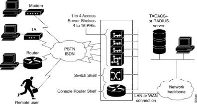
The Cisco AccessPath-LS3 Integrated Access System provides scalable dial-port counts and high-performance backbone routing in a distributed system architecture designed for the reliability and serviceability demanded by point-of-presence (POP) administrators who want to minimize downtime and service costs. Figure 1 shows the AccessPath-LS3 system with four access server shelves.
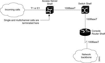
Figure 2 illustrates a typical AccessPath-LS3 stack environment.
T1 or E1 lines, supporting either ISDN Primary Rate Interface (PRI) or channel-associated signaling (CAS), feed into the AccessPath-LS3 system's Access Server Shelves. Each Access Server Shelf has four lines. With a maximum configuration of four Access Server Shelves, the AccessPath-LS3 system can accommodate up to 16 T1 or E1 connections.
For example, an Access Server Shelf has four lines. In a T1 Primary Rate Interface (PRI) configuration, each of these lines can handle 23 calls (23B+D). The maximum configuration of four Access Server Shelves provides a maximum capacity of 368 ISDN 1B+D BRI calls. The calls are terminated, aggregated, and multiplexed in the Access Server Shelf, then sent over a 100BaseT Fast Ethernet connection to the Console Router Shelf.
Figure 3 illustrates call pathways through the AccessPath-LS3 system.
The Cisco AccessPath-LS3 Integrated Access System supports the following features:
The AccessPath-LS3 system consists of the following components that can be mounted in your own rack system:
Each Access Server Shelf consists of the Cisco AS5300 universal access server, a versatile data communications platform that provides the functions of an access server, router, and digital modems in a single modular chassis. The access server is intended for Internet service providers (ISPs), telecommunications carriers, and other service providers that offer managed Internet connections, and also medium- to large-sized sites that provide both digital and analog access to users on an enterprise network. By terminating both analog and digital calls on the same chassis simultaneously, the access server provides you with a clear, simple, and easy migration path from today's analog dial access services to tomorrow's digital dial access services.
The access server consists of the following components:
The features of the Console Router Shelf (Cisco 3640) include:
The chassis includes four slots in which you can install modules. You can install any module into any available slot in the chassis. The slots are numbered from 0 to 3, as follows:
The Switch Shelf (FastHub 216T) is a managed 16-port 100BaseT Class II repeater for workgroups and server farms. It is a member of an extended network system of stackable, modular LAN and WAN products that increase LAN performance, connect remote offices and users, and provide secure access.
The Switch Shelf has 16 fixed 100BaseTX ports (with an alternative uplink port for connecting to other 100BaseTX hubs).
Before installing your Cisco AccessPath-LS3 Integrated Access System, you should consider the power and cabling requirements that must be in place at your installation site, the equipment you will need to install the system, and the environmental conditions your installation site must meet to maintain normal operation. This section guides you through the process of preparing for your Cisco AccessPath-LS3 Integrated Access System installation.
The following statements are general safety guidelines for use when working with the Cisco AccessPath-LS3 Integrated Access System.
Waarschuwing Dit waarschuwingssymbool betekent gevaar. U verkeert in een situatie die lichamelijk letsel kan veroorzaken. Voordat u aan enige apparatuur gaat werken, dient u zich bewust te zijn van de bij elektrische schakelingen betrokken risico's en dient u op de hoogte te zijn van standaard maatregelen om ongelukken te voorkomen. Voor vertalingen van de waarschuwingen die in deze publicatie verschijnen, kunt u het document Regulatory Compliance and Safety Information (Informatie over naleving van veiligheids- en andere voorschriften) raadplegen dat bij dit toestel is ingesloten.
Varoitus Tämä varoitusmerkki merkitsee vaaraa. Olet tilanteessa, joka voi johtaa ruumiinvammaan. Ennen kuin työskentelet minkään laitteiston parissa, ota selvää sähkökytkentöihin liittyvistä vaaroista ja tavanomaisista onnettomuuksien ehkäisykeinoista. Tässä julkaisussa esiintyvien varoitusten käännökset löydät laitteen mukana olevasta Regulatory Compliance and Safety Information -kirjasesta (määräysten noudattaminen ja tietoa turvallisuudesta).
Attention Ce symbole d'avertissement indique un danger. Vous vous trouvez dans une situation pouvant causer des blessures ou des dommages corporels. Avant de travailler sur un équipement, soyez conscient des dangers posés par les circuits électriques et familiarisez-vous avec les procédures couramment utilisées pour éviter les accidents. Pour prendre connaissance des traductions d'avertissements figurant dans cette publication, consultez le document Regulatory Compliance and Safety Information (Conformité aux règlements et consignes de sécurité) qui accompagne cet appareil.
Warnung Dieses Warnsymbol bedeutet Gefahr. Sie befinden sich in einer Situation, die zu einer Körperverletzung führen könnte. Bevor Sie mit der Arbeit an irgendeinem Gerät beginnen, seien Sie sich der mit elektrischen Stromkreisen verbundenen Gefahren und der Standardpraktiken zur Vermeidung von Unfällen bewußt. Übersetzungen der in dieser Veröffentlichung enthaltenen Warnhinweise finden Sie im Dokument Regulatory Compliance and Safety Information (Informationen zu behördlichen Vorschriften und Sicherheit), das zusammen mit diesem Gerät geliefert wurde.
Avvertenza Questo simbolo di avvertenza indica un pericolo. La situazione potrebbe causare infortuni alle persone. Prima di lavorare su qualsiasi apparecchiatura, occorre conoscere i pericoli relativi ai circuiti elettrici ed essere al corrente delle pratiche standard per la prevenzione di incidenti. La traduzione delle avvertenze riportate in questa pubblicazione si trova nel documento Regulatory Compliance and Safety Information (Conformità alle norme e informazioni sulla sicurezza) che accompagna questo dispositivo.
Advarsel Dette varselsymbolet betyr fare. Du befinner deg i en situasjon som kan føre til personskade. Før du utfører arbeid på utstyr, må du vare oppmerksom på de faremomentene som elektriske kretser innebærer, samt gjøre deg kjent med vanlig praksis når det gjelder å unngå ulykker. Hvis du vil se oversettelser av de advarslene som finnes i denne publikasjonen, kan du se i dokumentet Regulatory Compliance and Safety Information (Overholdelse av forskrifter og sikkerhetsinformasjon) som ble levert med denne enheten.
Aviso Este símbolo de aviso indica perigo. Encontra-se numa situação que lhe poderá causar danos físicos. Antes de começar a trabalhar com qualquer equipamento, familiarize-se com os perigos relacionados com circuitos eléctricos, e com quaisquer práticas comuns que possam prevenir possíveis acidentes. Para ver as traduções dos avisos que constam desta publicação, consulte o documento Regulatory Compliance and Safety Information (Informação de Segurança e Disposições Reguladoras) que acompanha este dispositivo.
¡Advertencia! Este símbolo de aviso significa peligro. Existe riesgo para su integridad física. Antes de manipular cualquier equipo, considerar los riesgos que entraña la corriente eléctrica y familiarizarse con los procedimientos estándar de prevención de accidentes. Para ver una traducción de las advertencias que aparecen en esta publicación, consultar el documento titulado Regulatory Compliance and Safety Information (Información sobre seguridad y conformidad con las disposiciones reglamentarias) que se acompaña con este dispositivo.
Varning! Denna varningssymbol signalerar fara. Du befinner dig i en situation som kan leda till personskada. Innan du utför arbete på någon utrustning måste du vara medveten om farorna med elkretsar och känna till vanligt förfarande för att förebygga skador. Se förklaringar av de varningar som förkommer i denna publikation i dokumentet Regulatory Compliance and Safety Information (Efterrättelse av föreskrifter och säkerhetsinformation), vilket medföljer denna anordning.
Follow these guidelines when working on equipment powered by electricity:
Warning Before working on a chassis or working near power supplies, unplug the power cord on AC units; disconnect the power at the circuit breaker on DC units. |
In addition, use the following guidelines when working with any equipment that is disconnected from a power source, but still connected to telephone wiring or other network cabling:
Electrostatic discharge (ESD) can damage equipment and impair electrical circuitry. It can occur if electronic printed circuit cards are improperly handled and can cause complete or intermittent failures. Always follow ESD prevention procedures when removing and replacing modules:
Check the power at your site to ensure that you are receiving "clean" power (free of spikes and noise). Install a power conditioner if necessary.
Warning Do not work on the system or connect or disconnect cables during periods of lightning activity. |
Warning This unit has more than one power cord. To reduce the risk of electric shock, disconnect the three to five power supply cords before servicing the unit. |
Note Each AccessPath-LS3 component should be connected to its own circuit to ensure sufficient operational power.
The AC power supply on each component has the following characteristics:
The following precautions will help you plan an acceptable operating environment for your AccessPath-LS3 system components and will help you avoid environmentally caused equipment failures:
Table 3 lists the operating and nonoperating environmental site requirements. The following ranges are those within which the Cisco AccessPath-LS3 Integrated Access System will continue to operate; however, a measurement that is approaching the minimum or maximum of a range indicates a potential problem. You can maintain normal operation by anticipating and correcting environmental anomalies before they approach a maximum operating range.
Table 3 Specifications for Operating and Nonoperating Environments
| Specification | Minimum | Maximum |
|---|---|---|
You can mount the AccessPath-LS3 components in a 19-, 23-, or 24-inch equipment rack. The following information will help you plan your equipment rack configuration:
Each of the AccessPath-LS3 components must be unpacked and mounted in a rack that you supply. Therefore, you may need some or all of the following to complete the installation:
In addition, you might need the following external equipment:
Before you can install the AccessPath-LS3 components you must unpack each box. Verify that all of the components listed on the packing slip that came with your order are present.
Do not unpack the equipment until you are ready to install it. If the final installation site will not be ready for some time, keep the components in the shipping containers to prevent accidental damage. When you are ready to install the system, proceed with the unpacking.
The routers, cables, publications, and any optional equipment you ordered may be shipped in more than one container.
When you unpack the containers, check the packing list to ensure that you received all the following items:
Inspect all items for shipping damage. If anything appears to be damaged, or if you encounter problems installing or configuring your components, contact customer service. Warranty, service, and support information is in the information packet that shipped with your equipment.
The Cisco AccessPath-LS3 Integrated Access System comes with five RJ-45 to RJ-45 straight-through Ethernet cables, two octal cables (optional with 16-port asynchronous module), and a package of labels. A label should be affixed to each end of each of the enclosed cables.
The 28 labels are marked as follows:
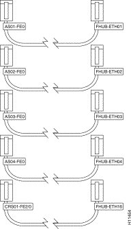
To affix the labels to an AccessPath-LS3 with 4 Access Server Shelves, follow these steps:
Step 2 On the second RJ-45 to RJ-45 cable, place the AS02-FE0 label on one end and the FHUB-ETH02 label on the other end.
Step 3 Repeat Step 2 on the next two RJ-45 to RJ-45 cables.
Step 4 On the last cable, place the CRS01-FE2/0 label on one end and the FHUB-ETH16 label on the other end.
Step 5 Set the RJ-45 to RJ-45 cables aside.
Note If you have the optional 16-port asynchronous module installed in the Console Router Shelf, continue with the next steps. If not, proceed to the next section "Rack-Mounting the Components."
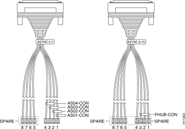
Step 6 On one octal cable, place the ASYNC 0-7 label on the end of the cable with the 68-pin connector.
Step 7 On the other octal cable, place the ASYNC 8-15 label on the end of the cable with the 68-pin connector.
Step 8 Place one of the following labels on the other end of each octal cable as shown in Table 4 and Figure 5:
| Cable Number | Label |
|---|---|
If you are planning to rack-mount the AccessPath-LS3 components, do so before making network and power connections. If you need to install modules or WAN interface cards, you can do so either before or after rack-mounting the components. Ideally, you would install modules or WAN interface cards when you have the best access to the router's rear panel.
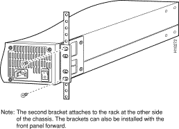
Each component is shipped with one set of brackets. Brackets for 19-inch racks are shipped unless the 23- or 24-inch brackets are specified at the time of the order.
After the brackets are fastened to each chassis, you can rack-mount them. Using your own screws, attach each chassis to the rack as shown in Figure 6. Mount each chassis in the rack in the order shown in Figure 1.
You must connect three different types of cables in order to complete the assembly of the AccessPath-LS3 system, as follows:
Note If you do not have the optional 16-port asynchronous module installed in the Console Router Shelf, you must connect the console to each component to complete the software configuration.
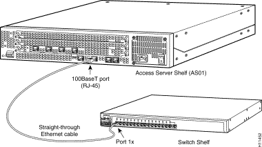
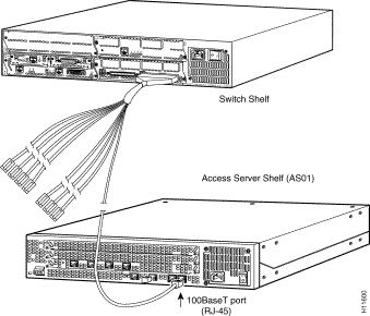
To connect the Access Server Shelves to the network, follow these steps:
For example, connect the cable end labeled AS03-FE0 to the 100BaseT Ethernet port on the AS03 Access Server Shelf. Connect the other end of the cable, labeled FHUB-ETH03, to the 3x port on the Switch Shelf. Repeat this procedure until each of the access servers is connected to a port on the Switch Shelf.
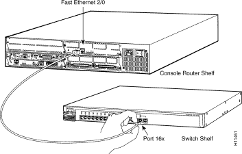
Step 2 Connect the cable labeled CRS01-FE2/0 to the Fast Ethernet port in slot 2 of the Console Router Shelf. Connect the other end of this cable, labeled FHUB-ETH16, to port 16x of the Switch Shelf, not port 16 (see Figure 8).
If you have the optional 16-port asynchronous module installed in the Console Router Shelf, the console port on each of the Access Server Shelves and the Switch Shelf is connected to the Console Router Shelf using the labeled octal cable. This configuration allows you to access the console port on each AccessPath-LS3 component by connecting to one of the asynchronous ports on the Console Router Shelf (Cisco 3640).
Connect the labeled 68-pin side of each octal cable to the appropriate port on the Console Router Shelf. For example, the cable marked ASYNC 0-7 should be connected to the port marked 0-7 on the Console Router Shelf. Connect the other end of each octal cable as follows:
Step 2 Repeat Step 1 until each of the Access Server Shelf console port is connected to the Console Router Shelf.
Step 3 Connect the RJ-45 connector on the octal cable marked FHUB-CON to the console port on the Switch Shelf (FastHub 216T).
Step 4 Secure the cable connectors marked SPARE.
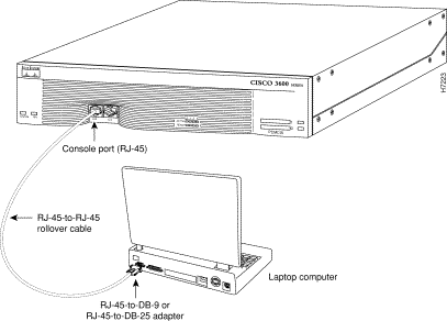
Take the following steps to connect a local terminal (an ASCII terminal or a PC running terminal emulation software) to the console port on the Console Router Shelf (Cisco 3640):
Step 2 Configure your terminal or PC terminal emulation software for 9600 baud, 8 data bits, no parity, and 1 stop bit.
Step 3 Perform the same procedure on each of the AccessPath-LS3 components to complete the software configuration.
To connect the power cords and power on each of the AccessPath-LS3 components, take these steps:
Step 2 Power ON the shelves. The LEDs labeled SYSTEM on the front or back panel should go on. The internal power supply fan should power on.
Warning Secure all power cabling when installing this unit to avoid disturbing field-wiring connections. |
The Ethernet and Fast Ethernet interfaces on the Console Router Shelf are used to connect the Cisco AccessPath-LS3 Integrated Access System to a LAN. The synchronous serial and ISDN BRI interfaces on the Console Router Shelf are used to connect the AccessPath-LS3 system to a WAN.
The cables required to connect the router to a network are not provided with the router. However, cables and transceivers can be ordered from Cisco. For ordering information, see the section, "Cisco Connection Online" at the end of this document.
Refer to the Cisco 3640 Router Installation and Configuration Guide for detailed instructions on making connections to your LAN or WAN.
This completes the hardware installation. Refer to the Cisco AccessPath-LS3 Integrated Access System Software Configuration document for instructions on bringing the Cisco AccessPath-LS3 Integrated Access System online.
This equipment has been tested and found to comply with the limits for a Class B digital device, pursuant to Part 15 of the FCC Rules. These limits are designed to provide reasonable protection against harmful interference in a residential installation. This equipment generates, uses, and can radiate radio frequency energy and, if not installed and used in accordance with the instructions, may cause harmful interference to radio communications. However, there is no guarantee that interference will not occur in a particular installation. If this equipment does cause harmful interference to radio or television reception, which can be determined by turning the equipment off and on, the user is encouraged to try to correct the interference by one or more of the following measures:
This Class B digital apparatus meets the requirements of the Canadian Interference-Causing Equipment Regulations.
Cet appareil numerique de la classe B respecte toutes les exigences du Reglement sur le materiel brouilleur du Canada.
This product is in conformity with the protection requirements of EU Council Directive 89/336/EEC on the approximation of the laws of the Member States relating to electromagnetic compatibility. This company cannot accept responsibility for any failure to satisfy the protection requirements resulting from a non-recommended modification of the product, including the fitting of non-Cisco option cards.
This product has been tested and found to comply with the limits for Class B Information Technology Equipment according to CISPR 22 /European Standard EN 55022. The limits for Class B equipment were derived for typical residential environments to provide reasonable protection against interference with licensed communication devices.
This is a Class B product based on the standard of the Voluntary Control Council for Interference from Information Technology Equipment (VCCI). If this is used near a radio or television receiver in a domestic environment, it may cause radio interference. Install and use the equipment according to the instruction manual.
Cisco Connection Online (CCO) is Cisco Systems' primary, real-time support channel. Maintenance customers and partners can self-register on CCO to obtain additional information and services.
Available 24 hours a day, 7 days a week, CCO provides a wealth of standard and value-added services to Cisco's customers and business partners. CCO services include product information, product documentation, software updates, release notes, technical tips, the Bug Navigator, configuration notes, brochures, descriptions of service offerings, and download access to public and authorized files.
CCO serves a wide variety of users through two interfaces that are updated and enhanced simultaneously: a character-based version and a multimedia version that resides on the World Wide Web (WWW). The character-based CCO supports Zmodem, Kermit, Xmodem, FTP, and Internet e-mail, and it is excellent for quick access to information over lower bandwidths. The WWW version of CCO provides richly formatted documents with photographs, figures, graphics, and video, as well as hyperlinks to related information.
You can access CCO in the following ways:
For a copy of CCO's Frequently Asked Questions (FAQ), contact cco-help@cisco.com. For additional information, contact cco-team@cisco.com.
Note If you are a network administrator and need personal technical assistance with a Cisco product that is under warranty or covered by a maintenance contract, contact Cisco's Technical Assistance Center (TAC) at 800 553-2447, 408 526-7209, or tac@cisco.com. To obtain general information about Cisco Systems, Cisco products, or upgrades, contact 800 553-6387, 408 526-7208, or cs-rep@cisco.com
![]()
![]()
![]()
![]()
![]()
![]()
![]()
![]()
Posted: Tue Jan 21 00:54:57 PST 2003
All contents are Copyright © 1992--2002 Cisco Systems, Inc. All rights reserved.
Important Notices and Privacy Statement.