|
|

This chapter provides preinstallation considerations, which are prerequisites to actual system installation. Use the information in this chapter to ensure that your site is properly prepared, that you have the equipment required for installation, and that you have all the cables and connectors you will need to connect your equipment to the STS-10x. The sections in this chapter provide:
The following guidelines are intended as a refresher to your previous training. You should have had previous training in working with electrical circuitry before attempting to install this equipment. Use your training and, foremost, common sense, to avoid damage to the equipment and serious injury to yourself. The following list is not inclusive of all potentially hazardous situations; be alert!
Follow these guidelines to prevent damage to the equipment or bodily harm:
To install your STS-10x, you will simply plug in cables. No special tools are required. However, you may need additional equipment to complete the connections to your Ethernet and RS-232 networks. With the exception of the RS-232 terminal, each piece of equipment listed below is offered as an option, and may have been shipped with your STS-10x. Information for ordering these options is provided in the Service and Support section in the front of this guide. You will need the following:
The STS-10x terminal server is intended for use in an office environment, which should be within the following specifications:
The STS-10x is factory-configured for either 110-volt or 220-volt operation. A label near the AC power connector, on the back of the server, indicates the correct voltage. If the voltage indicated on the label is different from the power outlet voltage, do not plug in the server. A voltage mismatch can cause equipment damage and may pose a fire hazard. Contact Cisco Systems Customer Service immediately, at the phone number provided in the "Service and Support" section of this publication.
When planning the cabling required for your system, consider distance limitations for signaling, electromagnetic interference, and connector compatibility. Each of these cabling considerations is described in the following sections.
As with all signaling systems, RS-232 signals can travel a limited distance at any given bit rate; generally, the slower the data rate, the greater the distance. Table 2-1 shows the standard relationship between bit rate and distance.
| Data Rate (in bps) | Distance (feet) | Distance (meters) |
|---|---|---|
| 2400 | 200 | 60 |
| 4800 | 100 | 30 |
| 9600 | 50 | 15 |
| 19200 | 25 | 7.6 |
| 38400 | 12 | 3.7 |
| 56000 | 8.6 | 2.6 |
When wires are run for any significant distance in an electromagnetic field, interference can occur between the field and the signals on the wires. This has two implications for the construction of terminal plant wiring:
If you use twisted-pair cables in your plant wiring with a good distribution of grounding conductors, the plant wiring is unlikely to emit radio interference. When exceeding the distances listed in Table 2-1, use a high quality twisted-pair cable with one ground conductor for each data signal.
To predict and remedy strong electromagnetic interference, you may need to consult experts in radio frequency interference (RFI). If you have wires exceeding the distances in Table 2-1, or you have wires that pass between buildings, give special consideration to the effect of a lightning strike in your vicinity. The electromagnetic pulse caused by lightning or other high-energy phenomena can easily couple enough energy into unshielded conductors to destroy electronic devices. If you have had problems of this sort in the past, you may want to consult experts in electrical surge suppression and shielding.
Most data centers cannot resolve the infrequent but potentially catastrophic problems just described without pulse meters and other special equipment. Therefore, take precautions to avoid these problems by providing a properly grounded and shielded environment, with special attention to issues of electrical surge suppression.
Terminals and modems typically use RS-232 DCE connectors. Since most modems are female DTE, they require a male DTE connector. At the terminal end of the RJ-45 to RJ-11 cable, a DB-25 adapter converts the RJ-11 output to DB-25. Two DB-25 adapters are shown in Figure 2-1, a male (DCE) and a female (DTE). One of each is included with your STS-10x. An RJ-11 connector, and its pin assignments, are shown in Figure 2-2.
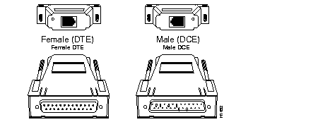
Table 2-2 shows the pin signals for male and female DTE and DCE adapters which convert the RJ-11 output to DB-25.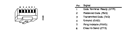
Signal | Direction | Modular Jack | Female DCE | Male DCE | Female DTE | Male DTE |
|---|---|---|---|---|---|---|
| DTR | From Cisco | 1 | 5 | 5 | 20 | 20 |
| RxD | To Cisco | 2 | 2 | 2 | 3 | 3 |
| TxD | From Cisco | 3 | 3 | 3 | 2 | 2 |
| GND | 4 | 7 | 7 | 7 | 7 | |
| RING | To Cisco | 5 | 22 | 22 | 5 | 5 |
| CTS | To Cisco | 6 | 20 | 20 | 5 | 5 |
If you plan to connect your STS-10x to a modem, you may want to build a 6-pin modem cable for the RS-232 interface. Table 2-3 lists the pin signals for the RJ-45 connectors at the STS-10x end, and for RS-232 DB-25 connectors at the modem end of the cable.
| Pin on STS-10x | To Pin on Modem | ||
|---|---|---|---|
| -- | Not used | -- | |
| -- | Frame Ground | -- | |
| 1 | Received Data | 3 | Received Data |
| 2 | Data Terminal Ready | 20 | Data Terminal Ready |
| 3 | Clear To Send | 5 | Clear To Send |
| 4 | Ring | 22 | Data Carrier Detect |
| 5 | Ground | 7 | Ground |
| 6 | Transmitted Data | 2 | Transmitted Data |
| -- | Not used | -- | |
| -- | Not used | -- | |
Your STS-10x, cables, documentation, and any optional equipment you ordered may be shipped in more than one container. When you unpack each shipping container, check the packing list to ensure you received all of the following:
Inspect all items for shipping damage. If anything appears damaged, or if you encounter problems during installation, refer to the "Service and Support" section in the front of this manual for instructions for contacting customer service.
Table 2-4 lists all the preinstallation and installation procedures for the initial installation of your terminal server. Use it as a guide while installing the STS-10x. Make a copy of this checklist and mark your entries as each procedure is completed. When installation is complete, insert it as the first entry in your site log (described in Chapter 3, Installation).
| Task | Verified by | Date |
|---|---|---|
| Installation checklist copied | ||
| Terminal server received | ||
| Documentation received | ||
| Chassis components verified | ||
| Background information placed in site log | ||
| Required tools available | ||
| Additional equipment available | ||
| Environmental specifications verified | ||
| Signal distance limits verified | ||
| Terminal server power voltages verified | ||
| Initial electrical connections established | ||
| RS-232 ASCII terminal attached to console port | ||
| Startup sequence steps completed | ||
| Initial system operation verified |
|
|