|
|

This chapter describes system component mechanical functions and emphasizes the importance of following the correct procedures to avoid unnecessary circuit card failures. This chapter is for background information only.
The Cisco AS5800 universal access server supports online insertion and removal (OIR). This feature allows you to remove and replace a trunk card or port-handling card, while the system is operating, without affecting system operation.
 |
Caution In order to maintain traffic flow in a single dial shelf controller (DSC) configuration, the DSC shouldn't be removed while the system is operational. If the DSC is removed, the interconnect link between the DSC and router shelf will be lost and all other dial shelf cards will go down. The router console port will display the following message: AUG 2 10:57:02.017 CST: %DSC_REDUNDANCY-3-BICLINK: Link to active DSC down |
Each dial shelf card contains a female connector that connects to a male connector on the system backplane. Each male backplane connector comprises a set of tiered pins in two lengths. The backplane pins send specific signals to the system as they make contact with the card connectors. The system assesses the signals it receives and the order in which it receives them to determine what event is occurring and what task it needs to perform, such as reinitializing new interfaces or shutting down removed ones.
Each dial shelf card is designed with two ejector levers to be used when you install or remove a card. The function of the ejector levers is to align and securely seat the card connectors in the backplane.
|
Caution Do not force the dial shelf cards into a slot, as this can damage the backplane connector pins if they are not aligned properly with the card connectors. |
To remove a dial shelf card without dropping calls or connections, you must first take the card out of service by using the busyout command to remove DS0s and modem resources from the available pool as calls are completed. The busyout command is run on a per card (slot) basis.
The busyout command has the format busyout shelf number/slot number, where shelf number is a user-designated value from 0 to 9999 and slot number is 0 to 5. The following example shows how to busyout the card in slot 0 on shelf 5:
If you are replacing a failed card, we recommend that you proceed as follows:
1. Use the busyout command to take the card out of service.
3. Install the new card in the same slot.
If you are replacing a dial shelf card with a new dial shelf card of the same type in the same slot, the system software recognizes the new dial shelf card interfaces and brings them up automatically. No additional configuration is needed. A dial shelf card installed in a different slot affects the clocking source.
 |
Note The system brings online only interfaces that match the current configuration and were previously configured as up; all other interfaces require that you configure them with the configure command. For information on the configure command, refer to the Cisco AS5800 Universal Access Server Operation, Administration, Maintenance, and Provisioning Guide that shipped with your system. |
You need the following supplies to install a dial shelf card. Contact a service representative for ordering information if you need additional materials.
To remove a dial shelf card from the (Cisco 5814) dial shelf, complete the following steps:
|
Caution Trunk cards weigh 8 lb (3.6 kg) each. Use two hands when removing or replacing a trunk card. |
|
Caution To avoid erroneous failure messages, remove or insert only one dial shelf card at a time. Also, after inserting or removing a dial shelf card, allow at least 15 seconds before removing or inserting another dial shelf card so that the system can reinitialize and note the current configuration of all interfaces. |
Step 2 Initialize the software busyout procedure by entering the following console command in privileged EXEC mode:
Step 3 Verify that the yellow maintenance LED on the card lights, which indicates that the card is offline and ready to be removed.
Step 4 Attach an ESD-preventive wrist strap between you and an unpainted chassis surface.
|
Caution To prevent ESD damage, handle cards by ejector levers and carrier edges only, and use an ESD-preventive wrist strap or other grounding device. |
Step 5 Disconnect all cables and secure them out of the way, using cable ties, if necessary.
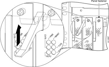
Step 6 Using a No. 2 Phillips screwdriver, loosen the panel fasteners at the top and bottom of the card front panel. (See Figure 1-1.)
Step 7 Pull either the top or bottom ejector lever away from the card's front panel to disengage the trunk card from the backplane connector. (See Figure 1-2.)
|
Caution Always use the ejector levers to disengage or seat dial shelf cards in the backplane. Failure to do so can cause erroneous system error messages indicating a card failure. However, do not use the ejector levers to lift or support the weight of the cards. |
Step 8 Grasp the ejector levers and pull the card partially out of the dial shelf slot until you can grasp the card front panel with one hand. Place your other hand under the card to balance the weight of the card as you pull it out of the slot. (See Figure 1-2.)
Step 9 For all cards, read the following warning, then proceed to Step 10.
Step 10 Pull the card straight out of the slot. Avoid touching the circuitry or any connector pins.
Step 11 Place the removed card on an antistatic mat or foam pad until you are ready to reinstall it in the chassis. If you plan to return the card to the factory, place it in an antistatic bag.
This completes the dial shelf card removal procedure. To install a dial shelf card, proceed to the following section, "Installing a Dial Shelf Card."
To install a new dial shelf card in the Cisco 5814 dial shelf, follow these steps:
|
Caution Trunk cards weigh 8 lb (3.6 kg) each. Use two hands when removing or replacing a card. |
|
Caution To avoid erroneous failure messages, remove or insert only one dial shelf card at a time. Also, after inserting or removing a dial shelf card, allow at least 15 seconds before removing or inserting another dial shelf card so that the system can reinitialize and note the current configuration of all interfaces. |
|
Caution To prevent ESD damage, handle cards by ejector levers and carrier edges only, and use an ESD-preventive wrist strap or other grounding device. |
Step 2 Carefully align the card carrier guides with the top and bottom grooves in the dial shelf slot. Avoid touching the circuitry or any connector pins.
Step 3 Slide the card into the slot until the ejector levers make contact with the chassis frame. (See Figure 1-2.)
Step 4 Seat the card in the backplane by pushing the card firmly until the ejector levers fold in toward the card's front panel and the front panel is flush with the chassis frame.
|
Caution Always use the ejector levers to disengage or seat trunk cards, modem cards, VoIP cards, or dial shelf controller cards in the backplane. Failure to do so can cause erroneous system error messages indicating a card failure. However, do not use the ejector levers to lift or support the weight of the cards. |
Step 5 Tighten the panel fasteners using a No. 2 Phillips screwdriver. This secures the backplane connection and ensures proper EMI shielding.
|
Caution Always tighten the panel fasteners. These fasteners prevent accidental removal and provide proper grounding for the system. |
Step 6 Repeat Step 2 through Step 5 for any other dial shelf cards that you want to install.
Step 7 Install a blank filler card (DS58-BLANK=) in all empty card slots to keep the chassis dust-free and maintain proper airflow.
|
Caution To prevent the overheating of internal components, always install blank filler cards in empty slots to maintain the proper flow of cooling air across the cards. |
This completes the dial shelf card replacement procedure.
![]()
![]()
![]()
![]()
![]()
![]()
![]()
![]()
Posted: Sun Mar 30 10:52:28 PST 2003
All contents are Copyright © 1992--2002 Cisco Systems, Inc. All rights reserved.
Important Notices and Privacy Statement.