cc/td/doc/product/access/acs_serv/as5200
hometocprevnextglossaryfeedbacksearchhelp
PDF

Table of Contents

Installing Dual T1/PRI or E1/PRI Feature Cards in Cisco AS5200 Universal Access Servers
Safety Recommendations
Software Requirements
Required Tools and Equipment
Feature Cards
Installing a Feature Card
Removing a Feature Card
Setting E1 Port Jumpers
Configuring the Dual T1/PRI and E1/PRI Feature Cards
Cisco Connection Online
CD-ROM/WWW Feedback

Installing Dual T1/PRI or E1/PRI Feature Cards in Cisco AS5200 Universal Access Servers


Product Numbers: AS52-2CT1=, AS52-2E1-U=, AS52-2E1-B=, AS52-2E1UPGD=

This document describes how to replace the Cisco AS5200 dual T1/PRI or E1/PRI feature cards and includes the following sections:

Use this document with the Regulatory Compliance and Safety Information publication that shipped with the Cisco AS5200.

Safety Recommendations

Follow these guidelines to ensure general safety:

Safety Warnings

Safety warnings appear throughout this publication in procedures that, if performed incorrectly, might harm you. A warning symbol precedes each safety warning.


.Means danger. You are in a situation that could cause bodily injury. Before you work on any equipment, you must be aware of the hazards involved with electrical circuitry and familiar with standard practices for preventing accidents. To see translations of the warnings that appear in this publication, refer to the Regulatory Compliance and Safety Information document that accompanied this device.

Waarschuwing  Dit waarschuwingssymbool betekent gevaar. U verkeert in een situatie die lichamelijk letsel kan veroorzaken. Voordat u aan enige apparatuur gaat werken, dient u zich bewust te zijn van de bij elektrische schakelingen betrokken risico's en dient u op de hoogte te zijn van standaard maatregelen om ongelukken te voorkomen. Voor vertalingen van de waarschuwingen die in deze publicatie verschijnen, kunt u het document Regulatory Compliance and Safety Information (Informatie over naleving van veiligheids- en andere voorschriften) raadplegen dat bij dit toestel is ingesloten.

Varoitus  Tämä varoitusmerkki merkitsee vaaraa. Olet tilanteessa, joka voi johtaa ruumiinvammaan. Ennen kuin työskentelet minkään laitteiston parissa, ota selvää sähkökytkentöihin liittyvistä vaaroista ja tavanomaisista onnettomuuksien ehkäisykeinoista. Tässä julkaisussa esiintyvien varoitusten käännökset löydät laitteen mukana olevasta Regulatory Compliance and Safety Information -kirjasesta (määräysten noudattaminen ja tietoa turvallisuudesta).

Attention  Ce symbole d'avertissement indique un danger. Vous vous trouvez dans une situation pouvant causer des blessures ou des dommages corporels. Avant de travailler sur un équipement, soyez conscient des dangers posés par les circuits électriques et familiarisez-vous avec les procédures couramment utilisées pour éviter les accidents. Pour prendre connaissance des traductions d'avertissements figurant dans cette publication, consultez le document Regulatory Compliance and Safety Information (Conformité aux règlements et consignes de sécurité) qui accompagne cet appareil.

Warnung  Dieses Warnsymbol bedeutet Gefahr. Sie befinden sich in einer Situation, die zu einer Körperverletzung führen könnte. Bevor Sie mit der Arbeit an irgendeinem Gerät beginnen, seien Sie sich der mit elektrischen Stromkreisen verbundenen Gefahren und der Standardpraktiken zur Vermeidung von Unfällen bewußt. Übersetzungen der in dieser Veröffentlichung enthaltenen Warnhinweise finden Sie im Dokument Regulatory Compliance and Safety Information (Informationen zu behördlichen Vorschriften und Sicherheit), das zusammen mit diesem Gerät geliefert wurde.

Avvertenza  Questo simbolo di avvertenza indica un pericolo. La situazione potrebbe causare infortuni alle persone. Prima di lavorare su qualsiasi apparecchiatura, occorre conoscere i pericoli relativi ai circuiti elettrici ed essere al corrente delle pratiche standard per la prevenzione di incidenti. La traduzione delle avvertenze riportate in questa pubblicazione si trova nel documento Regulatory Compliance and Safety Information (Conformità alle norme e informazioni sulla sicurezza) che accompagna questo dispositivo.

Advarsel  Dette varselsymbolet betyr fare. Du befinner deg i en situasjon som kan føre til personskade. Før du utfører arbeid på utstyr, må du vare oppmerksom på de faremomentene som elektriske kretser innebærer, samt gjøre deg kjent med vanlig praksis når det gjelder å unngå ulykker. Hvis du vil se oversettelser av de advarslene som finnes i denne publikasjonen, kan du se i dokumentet Regulatory Compliance and Safety Information (Overholdelse av forskrifter og sikkerhetsinformasjon) som ble levert med denne enheten.

Aviso  Este símbolo de aviso indica perigo. Encontra-se numa situação que lhe poderá causar danos físicos. Antes de começar a trabalhar com qualquer equipamento, familiarize-se com os perigos relacionados com circuitos eléctricos, e com quaisquer práticas comuns que possam prevenir possíveis acidentes. Para ver as traduções dos avisos que constam desta publicação, consulte o documento Regulatory Compliance and Safety Information (Informação de Segurança e Disposições Reguladoras) que acompanha este dispositivo.

¡Advertencia!  Este símbolo de aviso significa peligro. Existe riesgo para su integridad física. Antes de manipular cualquier equipo, considerar los riesgos que entraña la corriente eléctrica y familiarizarse con los procedimientos estándar de prevención de accidentes. Para ver una traducción de las advertencias que aparecen en esta publicación, consultar el documento titulado Regulatory Compliance and Safety Information (Información sobre seguridad y conformidad con las disposiciones reglamentarias) que se acompaña con este dispositivo.

Varning!  Denna varningssymbol signalerar fara. Du befinner dig i en situation som kan leda till personskada. Innan du utför arbete på någon utrustning måste du vara medveten om farorna med elkretsar och känna till vanligt förfarande för att förebygga skador. Se förklaringar av de varningar som förkommer i denna publikation i dokumentet Regulatory Compliance and Safety Information (Efterrättelse av föreskrifter och säkerhetsinformation), vilket medföljer denna anordning.

Safety with Electricity


Read the installation instructions before you connect the system to its power source.


Ultimate disposal of this product should be handled according to all national laws and regulations.

Only trained and qualified personnel should be allowed to install or replace this equipment.

Before working on a chassis or working near power supplies, unplug the power cord on AC units; disconnect the power at the circuit breaker on DC units.

Before working on equipment that is connected to power lines, remove jewelry (including rings, necklaces, and watches). Metal objects will heat up when connected to power and ground and can cause serious burns or weld to the terminals.

The ISDN connection is regarded as a source of voltage that should be inaccessible to user contact. Do not attempt to tamper with or open any public telephone operator (PTO)-provided equipment or connection hardware. Any hard-wired connection (other than by a nonremovable, connect-one-time-only plug) must be made only by PTO staff or suitably trained engineers.

To avoid electric shock, do not connect safety extra-low voltage (SELV) circuits to telephone-network voltage (TNV) circuits. LAN ports contain SELV circuits, and WAN ports contain TNV circuits. Some LAN and WAN ports use RJ-45 connectors. Use caution when connecting cables.

Hazardous network voltages are present in WAN ports regardless of whether power to the router is OFF or ON. To avoid electric shock, use caution when working near WAN ports. When detaching cables, detach the end away from the router first.

Follow these guidelines when working on equipment powered by electricity:

  • Locate the emergency power-OFF switch in the room in which you are working. Then, if an electrical accident occurs, you can quickly shut the power OFF.
  • Disconnect all power before doing the following:
    • Installing or removing a chassis
    • Working near power supplies
  • Do not work alone if potentially hazardous conditions exist.
  • Never assume that power is disconnected from a circuit. Always check.
  • Look carefully for possible hazards in your work area such as moist floors, ungrounded power extension cables, and missing safety grounds.
  • If an electrical accident occurs, proceed as follows:
    • Use caution; do not become a victim yourself.
    • Turn OFF power to the system.
    • If possible, send another person to get medical aid. Otherwise, determine the condition of the victim and then call for help.
    • Determine if the victim needs rescue breathing or external cardiac compressions; then take appropriate action.

Preventing Electrostatic Discharge Damage

Electrostatic discharge (ESD) can damage equipment and impair electrical circuitry. It occurs when electronic printed circuit cards are improperly handled and can result in complete or intermittent failures. Always follow ESD prevention procedures when removing and replacing cards. Ensure that the chassis is electrically connected to earth ground. Wear an ESD-preventive wrist strap, ensuring that it makes good skin contact. Connect the clip to an unpainted surface of the chassis frame to safely channel unwanted ESD voltages to ground. To properly guard against ESD damage and shocks, the wrist strap and cord must be used correctly. If no wrist strap is available, ground yourself by touching the metal part of the chassis.


For safety, periodically check the resistance value of the antistatic strap, which should be between 1 and 10 megohms (Mohm).

Software Requirements

The Cisco AS5200 dual T1/PRI or E1/PRI feature cards require Cisco IOS Release 11.2(7)P or higher.

Required Tools and Equipment

To install the dual T1/PRI or E1/PRI feature cards, you will also need the following tools and equipment (some of which are not included):

  • Medium-size flat-blade screwdriver (1/4 inch [0.625 cm])
  • ESD-preventive wrist strap and mat
  • Antistatic bag (optional)

Feature Cards

The Cisco AS5200 includes three slots in which you can install feature cards. You can install one of the following feature cards in any of the three available slots:

  • Dual T1/Primary Rate Interface (PRI) card with integrated channel service units (CSUs)
  • Dual E1/PRI card with one slot for an optional 12-port module

In the two remaining slots, you can install carrier cards.


The feature cards are not hot-swappable (that is, you cannot install or remove them when the power to the access server is ON). Be sure to turn OFF the power to the access server before installing or removing feature cards. Failure to do so can damage the access server.

Dual T1/PRI Card

The dual T1/PRI card (see Figure 1) routes incoming digital T1 lines to the 6-port or 12-port modules. The dual T1/PRI card provides RJ-48C connectors to terminate trunks. The dual T1/PRI card performs all necessary equalization and gain functions to support 6000 feet of 24-gauge unshielded cable. This card complies with all Bell Core standards relating to T1 (ANSI T1.403) alarms, loopbacks, and error detection. The dual T1/PRI card is equipped with integrated CSUs.

The dual T1/PRI card handles up to 48 digital signal level 0 (DS-0) channels from two trunks. Each channel carries either a pulse code modulation (PCM)-encoded voice channel or digital data. The dual T1/PRI card supports 64-kbps clear channel operation for data or voice channels and feature group B operation for voice channels.


Figure 1   Dual T1/PRI Card


Table 1 describes a typical maximum configuration. Note that the dual E1/PRI and the carrier cards are not slot dependent. Even though the system can contain 60 ports, the dual E1/PRI card can only support 48 simultaneous calls. The 12 extra ports are used for redundancy.

Table 1   Cisco AS5200 T1/PRI Port Configurations

Slot Card Maximum Ports

2

6-port MICA modem module carrier card or
12-port Microcom/V.110 carrier card

30 MICA modem ports or
24 Microcom/V.110 modem ports

1

6-port MICA modem module carrier card or
12-port Microcom/V.110 carrier card

30 MICA modem ports or
24 Microcom/V.110 modem ports

Indicators

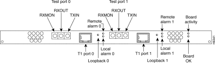
Table 2 describes the LEDs on the dual T1/PRI feature card. The LEDs indicate the current operating condition of the card. You can observe the LEDs, note any fault condition that the card is encountering, and contact your system administrator or a customer service representative if necessary. Refer to the sections "Cisco Connection Online," and "CD-ROM/WWW Feedback," for more information.

Table 2   Dual T1/PRI Feature Card LEDs

LED State Description

Board Activity

Flickering

The CSU/DSU in the card is communicating with a remote CSU/DSU.

Board OK

On

The T1/PRI card has passed initial power-ON diagnostics tests and is operating normally.

Loopback

On

A local or remote loopback diagnostic test is running on the associated T1 port.

Remote alarm

On

A remote alarm indication signal (AIS) has been received on the associated T1 port. The AIS is received when there has been a loss of signal (LOS).

Local alarm

On

The associated T1 port has detected local loss of signal (LOS) or out of frame (OOF) errors.

You can isolate problems on the dual T1/PRI card by connecting external test equipment to the RECEIVE jack to monitor signals coming into the RJ-48C port without interrupting normal data transmission. You can use the TRANSMIT jack to inject data, which interrupts normal data transmission.

Dual T1/PRI Card Network Specifications and Port Pinouts

Table 3 lists the network specifications you should consider before connecting the dual T1/PRI card to a network.

Table 3   Dual T1/PRI Card Network Specifications

Description Specification

Line rate

1.544 Mbps

Data rates

number x 56 kbps or number x 64 kbps, where number = 1 to 24

Standards

AT&T Pub. 62411, 54016, and 43801; ANSI T1.403

Table 4 lists the dual T1/PRI card port pinouts. Use a straight-through RJ-48C-to-RJ-48C cable to connect the T1 port to an RJ-48C jack.

Table 4   Dual T1/PRI Card Port (RJ-48C) Pinouts

RJ-48C8 Pin1 Description

1

Receive Ring from telco

2

Receive Tip from telco

4

Transmit Ring to telco

5

Transmit Tip to telco

1Pins 3, 6, 7, and 8 are not used.

Dual E1/PRI Card

The dual E1/PRI card (see Figure 2) is installed in the Cisco AS5200 to provide physical termination for two E1/PRI lines. The card is designed to support the E1 cable standard of 30 Bearer (B) channels for voice and data, one Data (D) channel for signaling, and one channel for framing. Each channel transmits at up to 64 kbps for a combined total of 2.048 Mbps for each E1/PRI line.

The Cisco AS5200 is used to service calls from users accessing remote services using a variety of network protocols. Calls are terminated in the Cisco AS5200 through up to 60 modems or modem/terminal adapter combinations. Your access server can support a combination of MICA modems, Microcom modems, and V.110 terminal adapters. User data can then be routed through the Ethernet or synchronous serial ports on the Cisco AS5200 chassis.


Figure 2   Dual E1/PRI Card


Table 5 describes a typical maximum configuration. Note that the dual E1/PRI and the carrier cards are not slot dependent. Even though the system can contain 72 ports, the dual E1/PRI card can only support 60 simultaneous calls. The 12 extra ports are used for redundancy.

Table 5   Cisco AS5200 E1/PRI Port Configurations

Slot Card Maximum Ports

2

6-port MICA modem module carrier card or
12-port Microcom/V.110 carrier card

30 MICA modem ports or
24 Microcom/V.110 modem ports

1

6-port MICA modem module carrier card or
12-port Microcom/V.110 carrier card

30 MICA modem ports or
24 Microcom/V.110 modem ports

0

Dual E1/PRI card with:
Optional 12-port Microcom modem card or
Optional 12-Port V.110 TA card


12 Microcom modem ports or
12 V.110 TAs

The following list describes the features of the Dual E1/PRI card:

  • Two DB-15 connectors for physically terminating two E1/PRI lines.
  • Channelized E1 support for assigning E1 time slots in 1 to 30 channel groups.
  • Optional 12 modem ports (Microcom) or terminal adapters for call termination on E1 channels. The optional 12 modems and two carrier cards with 48 modems are required if a modem is needed for each of the 60 B channels contained in two E1/PRI lines.
  • Optional 30 modem ports (MICA) for call termination on E1 channels.
  • LEDs to indicate the operating condition of the E1/PRI lines.
  • Full management of the dual E1/PRI card though a command line interface or CiscoWorks network management software.

The dual E1/PRI card includes two DB-15 ports for terminating 120-ohm balanced lines or 75-ohm unbalanced lines. Jumper settings on the card configure the ports for the line termination. Jumper positions and settings are listed in the section "Setting E1 Port Jumpers,".


The E1 interface card may only be installed in an ACA-permitted customer equipment or a data terminal equipment that is exempted from ACA's cabinet which has screw-down lids to stop user access to overvoltages on the customer equipment. The customer equipment has circuitry that may have telecommunications network voltages on them.

Incorrect connection of this or connected equipment to a general purpose outlet could result in a hazardous situation.

This equipment is to be installed and maintained by service personnel only as defined by AS/NZS 3260 Clause 1.2.14.3 Service Personnel.

The telecommunications lines must be disconnected 1) before unplugging the main power connector and/or 2) while the housing is open.

Indicators

Table 6 describes the LEDs on the dual E1/PRI feature card. The LEDs indicate the current operating condition of the card. You can observe the LEDs, note any fault condition that the card is encountering, and contact your system administrator or a customer service representative if necessary. Refer to the sections "Cisco Connection Online," and "CD-ROM/WWW Feedback," for more information.

Table 6   Dual E1/PRI Feature Card LEDs

LED State Description

Activity

Flickering

The CSU/DSU in the card is communicating with a remote CSU/DSU.

Board OK

On

The E1/PRI card has passed initial power-up diagnostics tests and is operating normally

Loopback

On

A local or remote loopback diagnostic test is running on the associated E1 port.

120-ohm

On

The port is configured for 120-ohm line termination.

Remote alarm

On

A remote alarm indication signal (AIS) has been received on the associated E1 port. The AIS is received when there has been a loss of signal (LOS).

Local alarm

On

The associated E1 port has detected local loss of signal (LOS) or out of frame (OOF) errors.

Dual E1/PRI Card Cable Assemblies and Pinouts

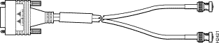
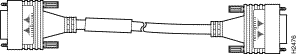
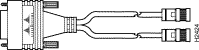
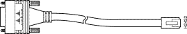
Four serial cables are available from Cisco Systems for connecting the dual E1/PRI card ports. All four have DB-15 connectors on the E1 end and BNC, DB-15, Twinax, or RJ-45 connectors on the network end. Figure 3, Figure 4, Figure 5, and Figure 6 show the E1 interface cables. Table 7 lists the pinouts for the E1 interface cables connecting to the dual E1/PRI card.


Figure 3   E1 Interface Cable for 75-Ohm, Unbalanced Connections (with BNC Connectors)


Figure 4   E1 Interface Cable for 120-Ohm, Balanced Connections (with DB-15 Connector)


Figure 5   E1 Interface Cable for 120-Ohm, Balanced Connections (with Twinax Connectors)


Figure 6   E1 Interface Cable for 120-Ohm, Balanced Connections (with RJ-45 Connector)


Table 7   E1 Interface Cable Pinouts

E1 End Network End
DB-151 BNC DB-15 Twinax RJ-452 RJ-45/NT3
Pin Signal4 Signal Pin Signal Pin Signal Pin Signal Pin Signal

9

TX Tip

TX Tip

1

TX Tip

TX-1

TX Tip

4

RX Tip

1

TX Tip

2

TX Ring

TX Shield

9

TX Ring

TX-2

TX Ring

5

RX Ring

2

TX Ring

10

TX Shield

-

2

TX Shield

Shield

TX Shield

6

RX Shield

3

TX Shield

8

RX Tip

RX Tip

3

RX Tip

RX-1

RX Tip

1

TX Tip

4

RX Tip

15

RX Ring

RX Shield

11

RX Ring

RX-2

RX Ring

2

TX Ring

5

RX Ring

7

RX Shield

-

4

RX Shield

Shield

RX Shield

3

TX Shield

6

RX Shield

1Any pins not described in this table are not connected.

2Connected as a network interface.

3Connected as a network terminal.

4TX = transmit; RX = receive.

Installing a Feature Card


Before working on a chassis or working near power supplies, unplug the power cord on AC units; disconnect the power at the circuit breaker on DC units.

Before opening the chassis, disconnect the telephone-network cables to avoid contact with telephone-network voltages.

Do not work on the system or connect or disconnect cables during periods of lightning activity.

For DC-powered units only, note the following warning:


Before performing any of the following procedures, ensure that power is removed from the DC circuit. To ensure that all power is OFF, locate the circuit breaker on the panel board that services the DC circuit, switch the circuit breaker to the OFF position, and tape the switch handle of the circuit breaker in the OFF position.

To install a new feature card, refer to Figure 7 and take these steps:


Step 1   Remove the feature card from the ESD-preventive shipping material.

Step 2   Slide the card into the slot until it touches the backplane connector.


Note If you have a dual E1/PRI card, change the jumper settings before installing the card. Refer to the section, "Setting E1 Port Jumpers," page 14 for more information.


Figure 7   Installing a Feature Card (Carrier Card Shown)


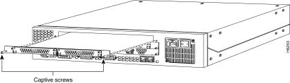
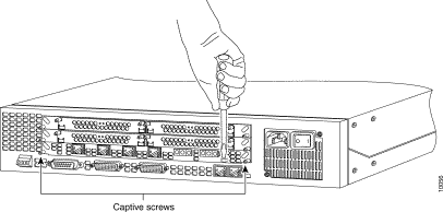
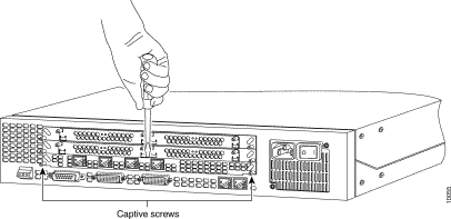
Step 3   Align the captive screws with their holes, and then seat the card completely.

Step 4   Tighten the two captive screws on the feature card to secure it to the chassis.

Step 5   If the Cisco AS5200 is configured with fewer than three cards, make sure that a blank slot cover is installed over each open slot to ensure proper airflow inside the chassis.

Removing a Feature Card


Before working on a chassis or working near power supplies, unplug the power cord on AC units; disconnect the power at the circuit breaker on DC units.

Before opening the chassis, disconnect the telephone-network cables to avoid contact with telephone-network voltages.

Do not work on the system or connect or disconnect cables during periods of lightning activity.

For DC-powered units only, note the following warning:


Before performing any of the following procedures, ensure that power is removed from the DC circuit. To ensure that all power is OFF, locate the circuit breaker on the panel board that services the DC circuit, switch the circuit breaker to the OFF position, and tape the switch handle of the circuit breaker in the OFF position.

Note      To remove a feature card, refer to Figure 8 and Figure 9 and take these steps:


Step 1   Attach an ESD-preventive wrist strap.

Step 2   Turn the power switch on the Cisco AS5200 OFF and disconnect site power.

Step 3   Remove all interface cables from the rear panel of the Cisco AS5200.

Step 4   Loosen the two captive screws that secure the feature card or blank slot cover to the chassis until each screw is free of the chassis.

Step 5   Hold the captive screws and gently pull the feature card free of the chassis.

Step 6   Set the removed feature card aside on an ESD-preventive mat.


The EMI protective devices on the feature cards are designed to make the cards fit tightly. When removing the cards, they might release suddenly. Exercise caution when removing cards.

Step 7   If the feature card is hard to remove:

  • For the Dual T1/PRI board, insert a flat-top screwdriver vertically into the prying slot of the board and gently pry the board loose. (See Figure 8.) Then, hold the captive screws and gently pull out the card until it slides free of the chassis.
  • For the Dual E1/PRI board, insert a flat-top screwdriver vertically into the center of the feature board and gently pry the board loose. (See Figure 9.) Then, hold the captive screws and gently pull out the card until it slides free of the chassis.

Figure 8   Prying the Dual T1/PRI Feature Card Loose


Figure 9   Prying the Dual E1/PRI Feature Card Loose


Setting E1 Port Jumpers

There are six 3-pin jumpers that configure the E1 termination for each port. The jumper settings are labeled on the printed circuit board for either 120-ohm balanced or 75-ohm unbalanced termination.

To set the E1 termination for each port, take the following steps:


Step 1   Place the dual T1/PRI card on an ESD-preventive mat as shown in Figure 10.


Figure 10   E1/PRI Card Jumpers

Step 2   Refer to Table 8 and set the six jumpers to configure E1 Port 0 for 75-ohm unbalanced or 120-ohm balanced termination. The jumper numbers and jumper settings are labeled on the printed circuit board shown in Figure 11.

Table 8   E1 Port 0 Jumper Settings

Jumper
Number
75-Ohm
Termination
120-Ohm
Termination
Jumper Description

J9

75

120

Receiver impedance

J11

75

120

Ground ring for 75 ohm

J12

Ground

120

Ground ring for 75 ohm, or ground shield for 120 ohm

J13

75

120

Transmit impedance

J14

75

120

Shield to connect to pin 7 for 120 ohm, or to ground ring for 75 ohm

J17

75

120

Software readable bit


Figure 11   E1 Port Jumpers


Step 3   Refer to Table 9 and set the six jumpers to configure E1 Port 1 for 75-ohm unbalanced or 120-ohm balanced termination. (See Figure 11.)

Table 9   E1 Port 1 Jumper Settings

Jumper
Number
75-Ohm
Termination
120-Ohm
Termination
Jumper Description

J3

75

120

Ground ring for 75 ohm

J4

Ground

120

Ground ring for 75 ohm

J5

75

120

Transmit impedance

J7

75

120

Shield connect to pin 7 for 120 ohm

J8

75

120

Receiver impedance

J18

75

120

Software readable bit

Configuring the Dual T1/PRI and E1/PRI Feature Cards

This section describes how to use the Cisco IOS software command line interface to configure basic Cisco AS5200 functionality. Basic Cisco AS5200 functionality includes LAN and WAN configuration (including ISDN PRI and channelized T1 and E1). Follow the procedures in this section to configure the Cisco AS5200 after installing a new T1/PRI or E1/PRI feature card.

This section does not describe every configuration possible—only a small portion of the most commonly used configuration procedures. For more advanced configuration topics, refer to the Cisco IOS configuration guide and command reference publications. These publications are available on the Documentation CD-ROM that came with your Cisco AS5200, on the World Wide Web from Cisco Connection Online (CCO), or you can order printed copies separately. Refer to the sections "Cisco Connection Online," and "CD-ROM/WWW Feedback," for more information.

For information about features supported by the Cisco IOS release installed on your Cisco AS5200, see the release notes that shipped with your chassis.

Prerequisites for Configuring the Cisco AS5200

Before you begin, make sure you have completed the following tasks:

  • Connect a console to the Cisco AS5200 and turn on the server. If you need instructions on how to connect a terminal console to the server, refer to the Cisco AS5200 hardware installation guide.
  • Write down the IP address of your Ethernet (LAN) interface.
  • Write down the set of available IP addresses to be assigned to dial-in IP clients.
  • Make sure your Cisco AS5200 is connected to the Ethernet network and the T1 PRI line. For more information about connecting cables, refer to the quick reference cards and the Cisco AS5200 Universal Access Server Hardware Installation Guide, which shipped with your Cisco AS5200.
  • Write down the ISDN switch type, framing type, and line code of your T1 PRI or E1 PRI line. Obtain this information from your telephone company service provider.

Note      If you do not type anything for 10 minutes while you are configuring your system, the session times out and is disconnected. If it times out, the message "Press RETURN to get started" appears. This is not an error. If this message appears, press Return and the Router> prompt appears again.


How to Find Command Options

This section explains how to display options for a command. To display options for a command, enter a ? at the configuration prompt, or after entering part of a command followed by a space. The configuration parser displays options available with the command. For example, if you were in global configuration mode and wanted to see all the keywords and arguments for the command arap, you would type arap ?.

Table 10 shows examples of this function:

Table 10   How to Find Command Options

Command Comment

5200> enable

Password: <password>

5200# 

Enters enable mode.

Enters the password.

You have entered enable mode when the prompt changes to 5200#.

5200# config terminal

Enter configuration commands, one per line. End with CNTL/Z.

5200(config)#

Enters global configuration mode and the prompt changes to 5200(config)#.

5200(config)# controller t1 ?

<0-1> Controller unit number

5200(config)# controller t1 1

Specifies the T1 controller that you want to configure using the controller T1 number global configuration command

5200(config-controller)#?

Controller configuration commands:

cablelength Specify the cable length for a DS1 link
cas-group Configure the specified timeslots for
CAS(Channel Associate Signals)
channel-group Specify the timeslots to channel-group
mapping for an interface
clock Specify the clock source for a DS1 link
default Set a command to its defaults
description Controller specific description
ds0 ds0 commands
exit Exit from controller configuration mode
fdl Specify the FDL standard for a DS1
data link
framing Specify the type of Framing on a DS1
link
help Description of the interactive help
system
linecode Specify the line encoding method for a
DS1 link
loopback Put the entire T1 line into loopback
no Negate a command or set its defaults
pri-group Configure the specified timeslots for
PRI
shutdown Shut down a DS1 link (send Blue Alarm)

Displays controller configuration commands.

5200(config-controller)# cas-group ?

<0-23> Channel number

Displays the options for the cas-group controller configuration command. This command is used to configure the channel-associated signaling on a T1 controller.

5200(config-controller)# cas-group 1 ?

timeslots List of timeslots in the cas-group

Displays the only command (timeslots) available in cas-group 1.

5200(config-controller)# cas-group 1 timeslots ?

<1-24> List of timeslots which comprise the cas-group

Displays the range for the timeslot option. Specifies a timeslot range of values from 1 to 24. You can specify timeslot ranges (for example, 1-24), individual timeslots separated by commas (for example 1, 3, 5), or a combination of the two (for example 1-3, 8, 17-24). The 16th time slot is not specified in the command line because it is reserved for transmitting the channel signaling.

5200(config-controller)# cas-group 1 timeslots 1-24 ?

service Specify the type of service
type Specify the type of signaling

Displays the two commands (service and type) available for the timeslots.

5200(config-controller)# cas-group 1 timeslots 1-24 type ?

e&m-fgb E & M Type II FGB
e&m-fgd E & M Type II FGD
e&m-immediate-start E & M Immediate Start
fxs-ground-start FXS Ground Start
fxs-loop-start FXS Loop Start
sas-ground-start SAS Ground Start
sas-loop-start SAS Loop Start

Lists supported signaling types.

5200(config-controller)# cas-group 1 timeslots 1-24 type e&m-fgb ?

dtmf DTMF tone signaling
mf MF tone signaling
service Specify the type of service
<cr>

Displays the types of channel-associated signaling available for the e&m-fgb type.

5200(config-controller)# cas-group 1 timeslots 1-24 type e&m-fgb dtmf ?

dnis DNIS addr info provisioned
service Specify the type of service
<cr>

Displays the options supported for the DTMF tone signaling option.

If you need further assistance, refer to the sections "Cisco Connection Online," and "CD-ROM/WWW Feedback," for more information.

Configuring ISDN PRI

Configure the Cisco AS5200 interfaces for ISDN PRI lines by using commands similar to Table 11 (specific commands vary with your configuration).

Table 11   Configuring ISDN PRI

Step Command Purpose
1

5200> enable

Password: <password>

5200# 

Enter enable mode.

Enter the password.

You have entered enable mode when the prompt changes to 5200#.

2

5200# config term

Enter configuration commands, one per line. End with CNTL/Z.

5200(config)#

Enter global configuration mode. You have entered global configuration mode when the prompt changes to 5200(config)#.

3

5200(config)# isdn switch-type [primary-4ess | primary-5ess | primary-dms100 | 

primary-net5 | primary-ntt | primary-ts014]

Enter your telco's switch type.

4

5200(config)# controller [t1 | e1] [0 | 1]

5200(config-controller)#

Enter controller configuration mode to configure your controller port. The controller ports are labeled 0 or 1 on the dual T1/PRI and dual E1/PRI cards.

5

5200(config-controller)# framing [esf | sf | crc4 | nocrc4]

Enter your telco's framing type.

6

5200(config-controller)# linecode [ami | b8zs | hdb3]

Enter your telco's line code type.

7

5200(config-controller)# clock source line primary

Enter the clock source for the line. Configure other lines as clock source secondary or clock source internal. Note that only one PRI can be clock source primary and only one PRI can be clock source secondary.

8

5200(config-controller)# pri-group timeslots [1-24 | 1-31]

Configure all channels for ISDN. For T1, enter pri-group timeslots 1-24. For E1, enter pri-group timeslots 1-31.

9

5200(config-controller)# controller t1 1

5200(config-controller)# framing esf

5200(config-controller)# linecode b8zs

5200(config-controller)# clock source line secondary

5200(config-controller)# pri-group timeslots 1-24

Repeat Steps 2 to 8 to configure each additional controller (there are two). In this example, note that the controller number is 1, instead of 0. And the clock source is secondary, instead of primary.

10

5200(config-controller)# end

5200#

%SYS-5-CONFIG_I: Configured from console by console

Return to privileged EXEC mode.

This message is normal and does not indicate an error.

Verifying ISDN PRI Configuration

To verify you have configured the ISDN PRI interfaces correctly, use the following commands. The following example shows output for the dual T1 PRI card.

  • Enter the show controller t1 or show controller e1 command and specify the port number:
5200# show controller t1 0
T1 0 is up.
No alarms detected.
Framing is ESF, Line Code is B8ZS, Clock Source is Line Primary.
Version info of slot 2: HW: 2, Firmware: 14, NEAT PLD: 13, NR Bus PLD: 19
Data in current interval (476 seconds elapsed):
0 Line Code Violations, 0 Path Code Violations
0 Slip Secs, 0 Fr Loss Secs, 0 Line Err Secs, 0 Degraded Mins
0 Errored Secs, 0 Bursty Err Secs, 0 Severely Err Secs, 0 Unavail Secs
Total Data (last 24 hours)
0 Line Code Violations, 0 Path Code Violations,
0 Slip Secs, 0 Fr Loss Secs, 0 Line Err Secs, 0 Degraded Mins,
0 Errored Secs, 0 Bursty Err Secs, 0 Severely Err Secs, 0 Unavail Secs
T1 1 is up.
No alarms detected.
Framing is ESF, Line Code is B8ZS, Clock Source is Line Primary.
Version info of slot 2: HW: 2, Firmware: 14, NEAT PLD: 13, NR Bus PLD: 19
Data in current interval (476 seconds elapsed):
0 Line Code Violations, 0 Path Code Violations
0 Slip Secs, 0 Fr Loss Secs, 0 Line Err Secs, 0 Degraded Mins
0 Errored Secs, 0 Bursty Err Secs, 0 Severely Err Secs, 0 Unavail Secs
Total Data (last 24 hours)
0 Line Code Violations, 0 Path Code Violations,
0 Slip Secs, 0 Fr Loss Secs, 0 Line Err Secs, 0 Degraded Mins,
0 Errored Secs, 0 Bursty Err Secs, 0 Severely Err Secs, 0 Unavail Secs

Note the following:

    • The controller must report being up.
    • No errors should be reported.
  • Enter the show isdn status command:
5200# show isdn status
The current ISDN Switchtype = primary-5ess
ISDN Serial0:23 interface
Layer 1 Status:
ACTIVE
Layer 2 Status:
TEI = 0, State = MULTIPLE_FRAME_ESTABLISHED
Layer 3 Status:
No Active Layer 3 Call(s)
Activated dsl 0 CCBs = 0
Total Allocated ISDN CCBs = 0
ISDN Serial1:23 interface
Layer 1 Status:
ACTIVE
Layer 2 Status:
TEI = 0, State = TEI_ASSIGNED
Layer 3 Status:
No Active Layer 3 Call(s)
Activated dsl 0 CCBs = 0
Total Allocated ISDN CCBs = 0
  • Note the following information for Serial 0:23 (the first half of the messages):
    • Layer 1 Status should be "Active."
    • Layer 2 Status should be "Multiple_Frame_Established." (It might take several seconds for Layer 2 status to appear.)
    • Layer 3 Status should be "No Active Layer 3 Call(s)."
  • The second half of the messages display information for Serial 1:23. Ignore those messages.
Tips

If you are having trouble, check the following:

  • Make sure the cable connection is not loose or disconnected if the Layer 1 Status is "Deactivated." This status message indicates a problem at the physical layer.
  • There might be a problem with your telco, or the framing and line code types you entered might not match your telco's. A Layer 2 error indicates that the Cisco AS5200 cannot communicate with the telco. There is a problem at the data link layer.

Configuring Channelized T1or E1

Configure the Cisco AS5200 for channelized T1 or E1 lines by using commands similar to those in Table 12.

Table 12   Configuring Channelized T1 or E1

Step Command Purpose
1

5200> enable

Password: <password>

5200# 

Enter enable mode.

Enter the password.

You have entered enable mode when the prompt changes to 5200#.

2

5200# config term

Enter configuration commands, one per line. End with CNTL/Z.

5200(config)#

Enter global configuration mode. You have entered global configuration mode when the prompt changes to 5200(config)#.

3

5200(config)# controller [t1 | e1] [0 | 1]

5200(config-controller)#

Enter controller configuration mode to configure your controller port. The controller ports are labeled 0 or 1 on the dual T1/PRI and dual E1/PRI cards.

4

5200(config-controller)# framing [esf | sf | crc4 | nocrc4]

Enter your telco's framing type.

5

5200(config-controller)# linecode [ami | b8zs | hdb3]

Enter your telco's line code type.

6

5200(config-controller)# clock source line primary

Enter the clock source for the line. Configure other lines as clock source secondary or clock source internal. Only one PRI can be clock source primary and only one PRI can be clock source secondary.

7

5200(config-controller)# cas-group 1 timeslots [1-24 | 1-31] <type>

Configure all channels and enter 1-24 for T1. If E1, enter 1-31. signaling types include: e&m-fgbE & M Type II FGB, e&m-fgdE & M Type II FGD, e&m-immediate-start E & M Immediate Start, fxs-ground-start FXS Ground Start, fxs-loop-startFXS Loop Start, sas-ground-startSAS Ground Start, sas-loop-start AS Loop Start. Note: For E1 using the Anadigicom converter, use the cas signaling option e&m-fgb.

8

5200(config-controller)# controller t1 1

5200(config-controller)# framing crc4

5200(config-controller)# linecode hdb3

5200(config-controller)# clock source line secondary

5200(config-controller)# cas-group 2 timeslots 1-24 type e&m-fgb

Repeat Steps 3 to 7 to configure each additional controller (there are two). In this example, note that the controller number is 1, instead of 0. The clock source is secondary, instead of primary. And the cas-group is 2, instead of 1.

9

5200(config-controller)# end

5200#

%SYS-5-CONFIG_I: Configured from console by console

5200#

Return to privileged EXEC mode.


This message is normal and does not indicate an error.

Verifying Channelized T1 or E1

To verify your controller is up and running and is not reporting errors, enter the show controller t1 or show controller e1 command and specify the port number.

5200# show controller t1 0
T1 0 is up.
No alarms detected.
Version info of slot 0: HW: 2, Firmware: 16, PLD Rev: 2

Note the following:

    • The controller must report being up.
    • No errors should be reported.
Tips

If you are having trouble, check to make sure the show controller t1 or show controller e1 output is not reporting alarms or violations.

Configuring the D Channels for Modem Signaling

For each ISDN PRI line, configure the ISDN D channels, which carry the control and signaling information for ISDN calls. Use the commands from Table 13 to configure the ISDN D channels.

Table 13   Configuring the D Channels for Modem Signaling

Step Command Purpose
1

5200> enable

Password: <password>

5200# 

Enter enable mode.

Enter the password.

You have entered enable mode when the prompt changes to 5200#.

2

5200# config term

Enter configuration commands, one per line. End with CNTL/Z.

5200(config)#

Enter global configuration mode. You have entered global configuration mode when the prompt changes to 5200(config)#.

3

5200(config)# interface serial [0:15 | 0:23]

5200(config-if)#

Enter serial interface configuration mode. After you have configured the controller, a corresponding D channel serial interface is created instantly. For example, serial interface 0:23 is the D channel for controller 0. You must configure each serial interface to receive incoming and send outgoing modem signaling.

4

5200(config-if)# ip address 172.16.253.254 255.255.255.0

Assign an IP address and subnet mask to the interface.

5

5200(config-if)# isdn incoming-voice modem

Configure all incoming voice calls to go to the modems.

6

5200(config-if)# dialer-group 1

Assign the serial interface to dialer group 1. The dialer group number is used with the dialer-list command to determine which packets will be "interesting" and activate the ISDN connection. Interesting packets meet the criteria specified by the dialer-list command.

7

5200(config-if)# encapsulation ppp

Change the default to encapsulation PPP so you can enter PPP commands.

8

5200(config-if)# ppp multilink

Enable PPP multilink on the serial interface.

9

5200(config-if)# ppp authentication chap pap

Enable CHAP and PAP authentication on the serial interface.

10

5200(config-if)# peer default ip address pool default

Support dial-in PC clients.

11

5200(config-if)# end

5200#

%SYS-5-CONFIG_I: Configured from console by console

5200#

Return to privileged EXEC mode.


This message is normal and does not indicate an error.

Verifying the D-Channel Configuration

To verify your D-channel configuration, enter the show interface command:

5200# show interface s0:23
Serial1:23 is up, line protocol is up
Hardware is DSX1
Interface is unnumbered. Using address of FastEthernet0 (15.0.0.60)
MTU 1500 bytes, BW 64 Kbit, DLY 20000 usec, rely 255/255, load 1/255
Encapsulation PPP, loopback not set
Last input 00:00:00, output 00:00:00, output hang never
Last clearing of "show interface" counters never
Queueing strategy: fifo
Output queue 0/40, 0 drops; input queue 0/75, 0 drops
5 minute input rate 0 bits/sec, 0 packets/sec
5 minute output rate 0 bits/sec, 0 packets/sec
54 packets input, 214 bytes, 0 no buffer
Received 0 broadcasts, 10 runts, 0 giants, 0 throttles
10 input errors, 0 CRC, 0 frame, 0 overrun, 0 ignored, 0 abort
53 packets output, 211 bytes, 0 overruns
0 output errors, 0 collisions, 10 interface resets
0 output buffer failures, 0 output buffers swapped out
1 carrier transitions
Timeslot(s) Used:24, Transmitter delay is 0 flags
Tips

If you are having trouble, use the following commands:

  • Enter the show interface serial command to check the serial interface. For a successful connection, LCP must be "Open" as shown on the sixth line of the following example:
5200(config)# show interface serial 0:0
Serial0 is up, line protocol is up
  Hardware is BRI
  MTU 1500 bytes, BW 64 Kbit, DLY 20000 usec, rely 255/255, load 1/255
  Encapsulation PPP, loopback not set, keepalive set (10 sec)
  LCP Open
  Open: IPCP, CDP
  Last input 00:00:02, output 00:00:02, output hang never
  Last clearing of "show interface" counters never
  Queueing strategy: fifo
  Output queue 0/40, 0 drops; input queue 0/75, 0 drops
  5 minute input rate 0 bits/sec, 0 packets/sec
  5 minute output rate 0 bits/sec, 0 packets/sec
     16536 packets input, 612628 bytes, 0 no buffer
     Received 0 broadcasts, 0 runts, 0 giants
     0 input errors, 0 CRC, 0 frame, 0 overrun, 0 ignored, 0 abort
     9036 packets output, 208401 bytes, 0 underruns
     0 output errors, 0 collisions, 51 interface resets
     0 output buffer failures, 0 output buffers swapped out
     378 carrier transitions
  • Enter the debug dialer command:
5200# debug dialer
PRI0: Dialing cause: PRI0: ip PERMIT
PRI0: No dialer string defined. Dialing cannot occur..
PRI0: Dialing cause: PRI0: ip PERMIT
PRI0: No dialer string defined. Dialing cannot occur..
PRI0: Dialing cause: PRI0: ip PERMIT
PRI0: No dialer string defined. Dialing cannot occur..
PRI0: Dialing cause: PRI0: ip PERMIT
PRI0: No dialer string defined. Dialing cannot occur..
PRI0: Dialing cause: PRI0: ip PERMIT
  • Enter the no debug dialer command to turn off the messages. If you do not turn off the messages, they will continue to display. See Table 14 for descriptions of the debug dialer messages.

    Table 14   Debug Dialer Messages

    Message Description

    PRI0: No dialer string defined. Dialing cannot occur.

    This message is displayed when a packet is received that should cause a call to be placed. However, there is no dialer string configured, so dialing cannot occur. This message usually indicates a configuration problem. Reenter the dialer string command in the configuration.

    PRI0: Attempting to dial xxxxxxxxxx

    This message indicates that a packet has been received that passes the dial-on-demand access lists. That packet causes dialing of a phone number. The xxxxxxxxxx variable is the number being called.

    PRI0: Unable to dial xxxxxxxxxx

    This message is displayed if for some reason the phone call could not be placed. This might be due to a lack of memory, full output queues, or other problems.

    PRI0: disconnecting call

    This message is displayed when the Cisco AS5200 attempts to hang up a call.

    PRI0: idle timeout

    PRI0: re-enable timeout

    PRI0: wait for carrier timeout

    One of these three messages is displayed when their corresponding dialer timer expires. They are mostly informational, but are useful when debugging a disconnected call or call failure.

  • If dialing cannot occur, check the configuration by entering the debug isdn q931 command:
5200# debug isdn q931
%LINEPROTO-5-UPDOWN: Line protocol on Interface Serial1/0:22, changed
state to up
ISDN Event: Call to 9086154535 dsl 3 at 64 Kb/s
TX -> SETUP dsl = 3 pd = 8 callref = 0x188C
Bearer Capability i = 0x8890
Channel ID i = 0xE1808397
Called Party Number i = 0xA1, '95163287448'
RX <- RELEASE_COMP dsl = 3 pd = 8 callref = 0x988C
Cause i = 0x83E020 - Mandatory IE missing
ISDN PRI 3: entering process_rxstate, CALL_CLEARED
ISDN PRI 3: received message 1F
ISDN Event: Hangup call to call id 0xCE2 on dsl 2
  • Enter the no debug isdn q931 command to turn off the messages. If you do not turn off the messages, they will continue to display. See Table 15 for descriptions of the debug messages.

    Table 15   Debug ISDN Messages

    Message Description

    TX ->

    Indicates this message is being transmitted from the local router (user side) to the network side of the ISDN interface.

    RX <-

    Indicates this message is being received by the user side of the ISDN interface from the network side.

    SETUP

    Indicates the SETUP message has been sent to initiate call establishment between peer network layers. The message can be sent from the local router or network.

    pd

    Indicates the protocol discriminator. The protocol discriminator distinguishes messages for call control over the user-network ISDN interface from other ITU-T1-defined messages, including other Q.931 messages. The protocol discriminator is 8 for call control messages such as SETUP.

    callref

    Indicates the call reference number in hexadecimal. The field value indicates the number of calls made from the router (outgoing calls) or the network (incoming calls). Note that the originator of the SETUP message sets the high-order bit of the call reference number to 0. The destination of the connection sets the high-order bit to 1 in subsequent call control messages, such as the CONNECT message. For example, callref = 0x04 in the request becomes callref = 0x84 in the response.

    Bearer Capability

    Indicates the requested bearer service to be provided by the network.

    i=

    Indicates the Information Element Identifier. The value depends on the field with which it is associated. Refer to the ITU-T Q.931 specification for details about the possible values associated with each field for which this identifier is relevant.

    Channel ID

    Indicates the Channel Identifier. The value 83 indicates any channel, 89 indicates the B1 channel, and 8A indicates the B2 channel. For more information about the Channel Identifier refer to ITU-T Q.931.

    Called Party Number

    Identifies the called party. This field is only present in outgoing SETUP messages. It can be replaced by the Keypad facility field. This field uses the IA5 character set.

    RELEASE

    Indicates that the sending equipment will release the channel and call reference. The recipient of this message should prepare to release the call reference and channel.

    RELEASE_COMP

    Indicates that the sending equipment has received a RELEASE message and has now released the call reference and channel.

1. ITU-T1 = International Telecommunication Union Telecommunication Standardization Sector.

Saving Configuration Changes

To avoid losing the Cisco AS5200 configuration, save it to NVRAM using the commands in Table 16.

Table 16   Saving Configuration Changes

Step Command Purpose
1

5200> enable

Password: <password>

5200# 

Enter enable mode.

Enter the password.

You have entered enable mode when the prompt changes to 5200#.

2

5200# copy running-config startup-config

Save the configuration changes to NVRAM so that they are not lost during resets, power cycles, or power outages.

3

5200(config-if)# end

5200#

%SYS-5-CONFIG_I: Configured from console 5200#

Return to privileged EXEC mode.


This message is normal and does not indicate an error.

Cisco Connection Online

Cisco Connection Online (CCO) is Cisco Systems' primary, real-time support channel. Maintenance customers and partners can self-register on CCO to obtain additional information and services.

Available 24 hours a day, 7 days a week, CCO provides a wealth of standard and value-added services to Cisco's customers and business partners. CCO services include product information, product documentation, software updates, release notes, technical tips, the Bug Navigator, configuration notes, brochures, descriptions of service offerings, and download access to public and authorized files.

CCO serves a wide variety of users through two interfaces that are updated and enhanced simultaneously: a character-based version and a multimedia version that resides on the World Wide Web (WWW). The character-based CCO supports Zmodem, Kermit, Xmodem, FTP, and Internet e-mail, and it is excellent for quick access to information over lower bandwidths. The WWW version of CCO provides richly formatted documents with photographs, figures, graphics, and video, as well as hyperlinks to related information.

You can access CCO in the following ways:

For a copy of CCO's Frequently Asked Questions (FAQ), contact cco-help@cisco.com. For additional information, contact cco-team@cisco.com.


Note      If you are a network administrator and need personal technical assistance with a Cisco product that is under warranty or covered by a maintenance contract, contact Cisco's Technical Assistance Center (TAC) at 800 553-2447, 408 526-7209, or tac@cisco.com. To obtain general information about Cisco Systems, Cisco products, or upgrades, contact 800 553-6387, 408 526-7208, or cs-rep@cisco.com.


CD-ROM/WWW Feedback

Cisco documentation and additional literature are available on a CD-ROM, which ships with your product. The Documentation CD-ROM, a member of the Cisco Connection Family, is updated monthly. Therefore, it might be more current than printed documentation. To order additional copies of the Documentation CD-ROM, contact your local sales representative or call customer service. The CD-ROM is available as a single item or as an annual subscription. You can also access Cisco documentation on the World Wide Web at http://www.cisco.com, http://www-china.cisco.com, or http://www-europe.cisco.com.

If you are reading Cisco product documentation on the World Wide Web, you can submit comments electronically. Click Feedback in the toolbar, select Documentation, and click Enter the feedback form. After you complete the form, click Submit to send it to Cisco. We appreciate your comments.

78-5016-01B0


hometocprevnextglossaryfeedbacksearchhelp
Posted: Sun Jan 19 11:10:07 PST 2003
All contents are Copyright © 1992--2002 Cisco Systems, Inc. All rights reserved.
Important Notices and Privacy Statement.