|
|

This chapter describes the Voice-over-IP (VoIP) card, a coprocessing card and software package that adds VoIP capabilities to Cisco AS5300 universal access servers. This chapter includes the following sections:
The VoIP capability enables a Cisco router to carry live voice traffic (for example, telephone calls and faxes) over an IP network. The VoIP card is available as a spare or a factory-installed card within the chassis.
The VoIP card contains multiple digital signal processor (DSP) modules. It uses the Cisco AS5300's Quad or Octal T1/E1 Public Switched Telephone Network (PSTN) interface and local-area network (LAN) or wide-area network (WAN) routing capabilities to provide VoIP packetized voice traffic to or from T1/E1 time-division multiplexing (TDM) traffic. Model AS53-6VOX supports 48/60 channels, and model AS53-VOXD supports 96/120 channels. Major applications of the VoIP cards include toll bypass, remote PBX presence over WANs, unified voice/data trunking, and plain old telephone service (POTS) Internet phone gateway. If you purchased a chassis with this card already installed, go directly to "Prerequisites ."
VoIP offers the following benefits:
The VoIP card has two primary applications. The first application (see Figure 5-1) provides a central-site telephony termination facility for VoIP traffic from multiple voice-equipped Cisco AS5300 remote office facilities.

The second application (see Figure 5-2) uses the VoIP card as a PSTN gateway for Internet telephone traffic. This leverages the standardized use of H.323-based Internet telephone client applications.
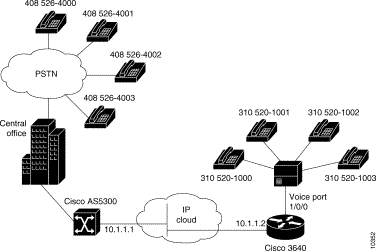
The basic hardware features of the VoIP card and the DSP modules are described in the following sections.
The VoIP card resides in one of the slots in the Cisco AS5300 universal access server. Up to five DSP modules can be installed onto the Voice card to perform voice processing for up to 30 B channels.
The DSP module provides voice compression and packetization services to the Voice card so that you can both configure and exapand it.
 | Caution Do not mix DSP modules on the same voice card. You cannot install a DSP 549 double-density module and a DSP 542 module on the same voice card, nor can you mix a voice card carrying only DSP 549 modules and a voice card carrying only DSP 542 modules in the same chassis. |
Before you can configure your Cisco AS5300 to use VoIP, you must first:
The VoIP card and the DSP modules require Cisco IOS Release 11.3(2)N or higher (plus images only).
 | Caution If you skipped in "Safety Warnings, Recommendations, and Tools Required," (in the beginning of this guide), go back to that chapter and read it now. This chapter provides important safety information and a list of tools you need to successfully remove and install cards without damaging your access server. |
To remove the VoIP card, perform the following steps:
 | Warning
Do not work on the system or connect or disconnect cables during periods of lightning activity. |
 | Caution The cards are not hot-swappable (that is, you cannot remove or install them when the power to the access server is ON). Be sure to turn OFF the power to the access server before installing or removing cards. Failure to do so can damage the access server. |
Step 2 Power OFF the access server. Turn the power switch on the access server OFF and disconnect site power. If using a DC-powered unit, refer to Figure 5-3 and complete steps a to d.
 | Warning Before performing any of the following procedures, ensure that power is removed from the DC circuit. To ensure that all power is OFF, locate the circuit breaker on the panel board that services the DC circuit, switch the circuit breaker to the OFF position, and tape the switch handle of the circuit breaker in the OFF position. |
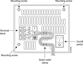
(a) Loosen the three locking screws for the negative, positive, and ground connectors on the DC power supply terminal block.
(b) Remove the -48 VDC wire from the terminal block negative connector (-) .
(c) Remove the +48 VDC wire from the terminal block positive connector (+) .
(d) Remove the safety ground (green wire) from the terminal block ground connector.
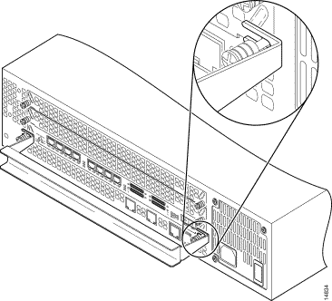
Step 3 On the rear panel of the access server, locate the VoIP card seen in Figure 5-4.
Step 4 Loosen the two captive screws that secure the VoIP card to the chassis until each screw is free of the chassis (see Figure 5-4).

Step 5 Insert the card removal tool so that the slots in each arm of the tool are behind the shoulder of each captive screw, as shown in Figure 5-5, and carefully pull the removal tool toward you until the VoIP card slides free of the chassis.
 | Caution The EMI protective devices on the VoIP card are designed to make the card fit tightly. When removing the card, they can release suddenly. Exercise caution when removing the VoIP card with the card removal tool. |
Step 6 Set the removed VoIP card aside on an ESD-preventive mat.
Step 7 Continue with one of the following sections:
To remove DSP modules:
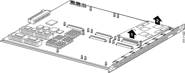
Step 2 On the VoIP card, locate the DSP module you will replace (see Figure 5-6).
Step 3 Orient the VoIP card so that the DSP module socket is facing toward you.
Step 4 Gently pry the front edge of the DSP module away from the standoffs and the socket, as indicated by the arrow labeled 1 in Figure 5-6.
Step 5 When the DSP module is free of the socket, gently pry the back edge of the DSP module away from the other set of standoffs, as indicated by the arrow labeled 2 in Figure 5-6.
Step 6 Continue with the following section, "Removing DSP Modules."
To install a DSP module, first seat the DSP module in the socket, then press all four corners onto their respective standoffs, as shown in Figure 5-7.
 | Caution Do not mix DSP modules on the same voice card. You cannot install a DSP 549 double-density module and a DSP 542 module on the same voice card, nor can you mix a voice card carrying only DSP 549 modules and a voice card carrying only DSP 542 modules in the same chassis. |
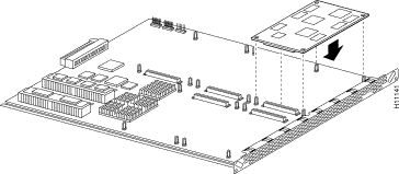
Step 7 Continue with the following section, "Installing VoIP Cards" to install the VoIP card.
To install a VoIP card:
Step 2 Slide the VoIP card into the slot until it touches the backplane connector.
Step 3 Align the captive screws with their holes, and then seat the VoIP card completely.
Step 4 Tighten the two captive screws (see Figure 5-8) to secure the VoIP card to the chassis.

Step 5 If the access server is configured with fewer than three cards, make sure that a blank slot cover is installed over each open slot to ensure proper airflow inside the chassis.
Step 6 Reconnect the AC power cord. Or, if using DC power, refer to Figure 5-9, and then complete steps a to d.

 | Caution Do not overtorque the terminal block contact screws. The recommended torque is 8.2 ± 0.4 inch-lb. |
(a) Insert the safety ground (green wire) into the terminal block ground connector and tighten the locking screw. Ensure that no bare wire is exposed.
(b) Insert the +48 VDC wire into the terminal block positive connector (+) and tighten the locking screw. Ensure that no bare wire is exposed.
(c) Insert the -48 VDC wire into the terminal block negative connector (-) and tighten the locking screw. Ensure that no bare wire is exposed.
(d) Make sure the power supply cord is secured to the cable strain-relief clamps on the DC power supply with cable ties.
 | Warning After wiring the DC power supply, remove the tape from the circuit breaker switch handle and reinstate power by moving the handle of the circuit breaker to the ON position. |
Step 7 Power ON the access server.
The internal power supply fan should power on.
Step 8 Continue with the following section, "Upgrading VoIP Card VCWare ."
To download VCWare to your Voice card, you need to:
1. Identify Voice cards in the system and determine whether the VFC is in VCWare mode or ROM Monitor mode. This determines how you download software to the VFC.
2. Check to see that the version of VFC ROM Monitor software is compatible with your installed Cisco IOS image. VFC ROM Monitor version 1.2 requires Cisco IOS image 0.14.1 (1.6 NA1) or later.
3. Download the software using the appropriate procedure.
Use the following steps to identify the Voice cards in the system and determine whether the VFC is in VCWare mode or ROM Monitor mode. This determines how you download software to the VFC.
| Step | Command | Purpose |
|---|---|---|
| 1 | | Enter enable mode. Enter the password. You have entered enable mode when the prompt changes to |
| 2 | | Determines the number of Voice cards in the system, the slot number for each card, and the VFC mode (VCWare or ROM Monitor) in which they are running. The VFC mode is indicated as follows:
Note the location and the mode type for each voice card. You will need this information when you upgrade the VCWare. |
| 3 | | Go to one of the following procedures:
|
Use the steps that follow to download new voice software if your voice card is running in VCWare mode. When downloading from a diskette, first copy the software from the diskette to a TFTP server. After the software is on the TFTP server, begin the following steps.
 | Caution
Erasing the VFC files can result in system outage or the corruption of your VFC board. Check to ensure that the correct version of software resides on your TFTP server before continuing.
|
To check that you have successfully downloaded the software:
5300# show vfc 1 dir


Files in slot 1 VFC flash:
	File Name 	Size (Bytes)
1.	vcw-vfc-mz.1.0.bin 	291292
5300# show vfc 1 def (full word is default-file)

Default File List for VFC in slot 1:

1. btl-vfc-l.1.0.bin
2. cor-vfc-l.1.0.bin
3. bas-vfc-l.1.0.bin
4. cdc-g729-l.1.0.bin
5. fax-vfc-l.1.0.bin
6. jbc-vfc-l.1.0.bin

5300# show vfc 1 cap-list


Capability List for VFC in slot 1:

1. fax-vfc-l.0.13.0.bin
2. bas-vfc-l.0.13.0.bin
3. cdc-g729-l.0.13.0.bin
4. cdc-g711-l.0.13.0.bin

5300#
If you are having trouble downloading the voice card software in VCWare mode, try the following:
5300# show vfc 1 board

VFC board state is UP, vfc status VCWARE running(0x4)
VFC board in slot 1 with 18 dsps
5300#
5300# sh vfc 1 ver vcw


Voice Feature Card in Slot 1:
     VCware Version     :  1.0
     ROM Monitor Version:  1.2
     DSPware Version    :  1.0
Use the steps that follow to download new voice software if your voice card is running in ROM Monitor mode. When downloading from a diskette, first copy the software from the diskette to a TFTP server. After the software is on the TFTP server, begin the following steps.
 | Caution Erasing the VFC files can result in system outage or the corruption of your VFC board. Check to ensure that the correct version of software resides on your TFTP server before continuing. |
| Step | Command | Purpose |
|---|---|---|
| 1 (optional) | | Note See the Caution before this table before continuing. Erase the contents of the VFC Flash memory in the selected voice card. This may take awhile. Press y to continue. |
| 2 | | Use TFTP to download the new VCWare to VFC Flash memory. Note The image name must begin with "vcw-" (all lowercase) and no other character can be in front of the "vcw-," so no directory path should be included at the beginning of the image name. Be absolutely certain to get the name right. If one character or space is wrong, the file will not be recognized and will not be copied over. |
| 3 | | Reset the voice card so you can add the new VCWare image into the voice card. |
| 4 | | Reenter enable mode. Enter the password. You have entered enable mode when the prompt changes to |
| 5 | | Check to see if the VFC is back up in ROM Monitor mode. |
| 6 | | Verify that VCWare is in the VFC Flash memory. |
| 7 | | Unbundle the DSPWare from the VCWare and configure the default file list and the capability list. |
| 8 | | Verify that the DSPWare is unbundled. |
| 9 | | Verify that the default file list is initiated. |
| 10 | | Verify that the capability list is initiated. |
| 11 | | Reboot the Cisco AS5300 so these changes take effect. |
To check that you have successfully downloaded the software:
5300# show vfc 1 dir


Files in slot 1 VFC flash:
	File Name 	Size (Bytes)
1.	vcw-vfc-mz.1.0.bin 	291292
5300# show vfc 1 def (full word is default-file)

Default File List for VFC in slot 1:

1. btl-vfc-l.1.0.bin
2. cor-vfc-l.1.0.bin
3. bas-vfc-l.1.0.bin
4. cdc-g729-l.1.0.bin
5. fax-vfc-l.1.0.bin
6. jbc-vfc-l.1.0.bin

5300# show vfc 1 cap-list


Capability List for VFC in slot 1:

1. fax-vfc-l.0.13.0.bin
2. bas-vfc-l.0.13.0.bin
3. cdc-g729-l.0.13.0.bin
4. cdc-g711-l.0.13.0.bin

5300#
If you are having trouble downloading the voice card software in ROM Monitor mode, try the following:
5300# show vfc 1 board

VFC board state is UP, vfc status VCWARE running(0x4)
VFC board in slot 1 with 18 dsps
5300#
5300# sh vfc 1 ver vcw


Voice Feature Card in Slot 1:
     VCware Version     :  1.0
     ROM Monitor Version:  1.2
     DSPware Version    :  1.0
The actual configuration procedure depends entirely upon the topology of your voice network, but, in general, you need to complete the following configuration tasks:
1. Configure IP Networks for Real-Time Voice Traffic.
2. Configuring Voice Ports for ISDN PRI.
3. Configuring the D Channels.
4. Configuring the Dial Peers.
5. Configuring Voice Network Data.
For detailed procedures, see the Cisco AS5300 Universal Access Server Software Configuration Guide. You can find the most up-to-date version of this manual online from either CCO or the CD-ROM.
For detailed examples of command output, see the Voice Over IP for the Cisco AS5300 Configuration Guide. You can find the most up-to-date version of this manual online from either CCO or the CD-ROM.
![]()
![]()
![]()
![]()
![]()
![]()
![]()
![]()
Posted: Fri Aug 17 18:16:23 PDT 2001
All contents are Copyright © 1992--2001 Cisco Systems, Inc. All rights reserved.
Important Notices and Privacy Statement.