|
|

This document begins with information specific to this initial release of the Dual E1/PRI network application and interface cards, followed by a summary of the contents of each section and information on additional sources for related technical information. An overview of Euro ISDN and a brief discussion of ordering E1 service from your service provider concludes this document.
Release 1.0 of the Dual E1/PRI network application card (NAC) and the E1 network interface card (NIC) supports Euro ISDN Primary Rate Interface (PRI) call routing protocols. Refer to the "Call Processing and Routing" section in this document for details if you have a need for the following features in your installation:
These features require support by the Quad V.34 Analog/Digital Modem (at least version 3.1). To implement these features from a management station, the network management card and your SNMP management software should also be at compatible release levels (at least version 4.0).
This document covers both the hardware and software aspects of the E1 network interface card (NIC) and the Dual E1/PRI network application card (NAC).
Note For additional information, please consult the Cisco Access Server 5100 User Guide or your SNMP management software.
The sections of the document are as follows:
Provides a general discussion of Euro ISDN service with an emphasis on PRI features along with a discussion of some considerations to take into account when ordering E1/PRI service.
Contains a functional description of the components of this card and a description of the interface connections.
Provides a functional description of the components of this card and a description of how to configure hardware switches.
Provides instructions for installing the cards, discusses startup issues and chassis configuration and diagnostic information.
Provides information on the user interface connections available to manually configure the cards through software control.
Discusses software signaling and routing processes used by the cards to receive, route, and terminate calls.
Provides a menu-by-menu description of the operator interface screens used to manually configure the cards through software control and to view the card alarm and status indicators.
Provides detailed information about the interfaces and mechanicals of the cards.
Although established international telecommunications standards and nomenclatures are widely used and accepted throughout the world, each country has commonly used words and abbreviations that are unique to that country or area. These terms include the following.
In order to minimize confusion over common terminology in this document, where possible, such terms are defined when first used.
European Integrated Services Digital Network (Euro ISDN) service provides for the transmission of digital data over telephone lines. This section provides general information on the features and capabilities of Euro ISDN with a focus on the ISDN Primary Rate Interface (PRI).
ISDN uses out of band signaling techniques to transmit data and to provide communications networks with universal connectivity over digital lines. Euro ISDN is based on European Telecommunications Standard Institute (ETSI) and International Telephone Union-Telecommunications (ITU-T) standards.
ISDN provides three very broad categories of services that support a variety of user requirements.
Euro ISDN provides digital transmission of voice, data, studio-quality sound, and still and moving images. ISDN calls maximize the use of available resources, reduce call setup times, provide flexibility in call routing via software configuration, and minimize the rejection of calls.
Currently, two types of ISDN transmission rates are available—Basic Rate Interface (BRI) and Primary Rate Interface (PRI).
Both BRI and PRI service use two types of channels—B-channels and D-channels. The B-channels (bearer channels) carry user data and the D-channels carry signaling data.
In both BRI and PRI, through the use of inverse multiplexing or bonding, several combinations of B- and D-channels are possible. These multiple channels are called H-channels. Examples of H-channels, carrying both circuit/packed switched user data, include:
Note H12 is only possible in services that use multiple E1 lines where signaling is done through another D-channel.
ISDN BRI service transmits digital data by dividing the existing twisted pair local loop into three separate channels—two 64 Kbps B-channels and one 16 Kbps D-channel. This is also referred to as 2B+D service. The B-channels always carry user data and the D-channel carries all signaling information and low-speed packet data.
In countries using E1 span lines, ISDN PRI service provides transmission of digital data over 30 B-channels (64 Kbps) and one D-channel (64 Kbps) plus one framing channel (64 Kbps) for a total bandwidth of 2.048 Mbps using an E1 span line. This is sometimes referred to as 30B+D service.
Note In countries that use T1 span lines, PRI service utilizes 23 B-channels and 1 D-channel (or 23B+D) for a total bandwidth of 1.544 Mbps.
Incoming calls are sensed and routed using device detection schemes to the appropriate devices based on whether they are B-channel user or D-channel signaling calls.
The 30 Euro ISDN PRI B-channels each carry user data at transmission speeds of 64 Kbps. ISDN B-channels usage allocations are sometimes aggregated, through software control, into pipes (H-channels) to accommodate various load requirements.
The PRI D-channel(s) are used to carry signaling data at 64 Kbps for all of the B-channels on an E1 interface. Signaling information includes call setup and tear down messages and out-of band information. This arrangement clears the B-channels to carry only user data.
Setup and tear down information includes called number, bearer capability, B-channel time slot assignment, etc. The D-channel protocol is defined in ITU-T Q.921 and Q.931. This message-based system allows calls to be setup much faster than robbed-bit E1 setup times.
In systems using multiple E1 span lines, the D-channel one span line may be configured to do the signaling for the other span line. For example, with two E1/PRI span line connections, E1/PRI span 1 could have 30B+1D and E1/PRI span 2 could have 31B. In this case, the span 1 D-channel carries the signaling data for both span lines. This configuration is referred to as Nonfacility associated signaling (NFAS).
With E1/PRI service, time slot 0 is used for frame alignment and time slot 16 is used for the D-channel.
Rate adaptation is a process whereby terminal adapters negotiate or adjust bandwidth to meet the requirements of each call. Euro ISDN initiated calls exchange a burst of information to and from the customer site and PTT on the D-channel, including the nature of the call, the type of bearer service requested, and the phone number called. Rate adaptation and signaling protocols, used to standardize the transmission of this information, include:
Additional information on ISDN features and capabilities may be available through your service provider or through the following online resources:
European ISDN User Forum |
|
Dan Kegel's ISDN Page |
|
This section is designed to prepare you to begin to deal with your E1/PRI provider. If you need additional information, contact Cisco Systems Product Support.
E1/PRI service provisioning requirements may vary according to customer application requirements and the availability of service. There are two major elements that must be considered when ordering E1/PRI service:
When ordering E1/PRI service for use with the E1/PRI NIC and NAC cards, your service provider will probably require information about the following parameters in addition to the D-channel provisioning requirements:
The E1/PRI NIC and NAC cards support the subset of Euro ISDN standardized switch compatibility type known as ETS ICTR-4.
The E1/PRI frame type service that is supported by the E1/PRI cards is common channel signaling (CCS) with CRC-4 error detection. This standard is defined in ITU-T G.704.
The CCS frame type with CRC-4 error detection is recommended because it minimizes potential framing problems and false alarm events. This frame type is also known as CEPT.
Line coding schemes ensure a sufficient density of 1's in the bit stream, as required by the Dual E1/PRI standard for clock synchronization. The Dual E1/PRI software supports the high-density bipolar-3 (HDB3) line coding scheme.
HDB3 is a variant of alternate mark inversion (AMI) line coding. It provides clear unrestricted channel access to both the PRI B- and D-channels. In other words, data may be sent over the B- and D-channels without any restrictions to content.
Proper provisioning of the PRI D-channel before installation of the E1/PRI cards will help to ensure that your system properly performs the customized applications for which it is intended.
Before contacting your E1/PRI provider, it is advisable to determine exactly what types of applications you will be using, including:
This section provides information on the features, functions, and connectors available through the Dual E1 network interface card (NIC). This card is a companion card to the Dual E1/PRI network application card (NAC).
The Dual E1 NIC is designed to be inserted in the back of the AS5100 chassis and plugged into the chassis midplane. The midplane provides connectors on the front for NACs and connectors on the back for NICs. The cards communicate through multiple data buses located in the midplane. See the "Installation" section later in this document for information on the location of this card in the chassis.
The Dual E1 NIC is a surface mounted card that provides the following features:
The Dual E1 NIC provides the line interface circuitry between the E1 span line(s) and the E1/CEPT frame on the Dual E1/PRI NAC.
The NIC has a built-in line interface unit (LIU) that provides the interface to each E1/PRI span line. The LIU contains automatic gain control (AGC), auto-equalization, and data recovery. It also recovers the E1 2.048 MHz network clock, which is used by the E1/PRI NAC to clock the data to the E1 framers. Depending on the configuration, the network clock may be used by the AS5100 chassis as a timing source.
The Dual E1 NIC has the drivers and receivers for the EIA-TIA-232 serial interface required to perform a software download. However, there is no software-driven component on the E1 NIC. The card is managed completely by the E1/PRI NAC.
When the Dual E1/PRI NAC is removed, it sends a nonframed all 1's pattern to the PTT. This is a standard alarm sequence that signals the PTT that the equipment is down.
Note If the NAC is removed for extended periods of time, the PTT may elect to make the span lines inactive. Some PTTs discontinue the signal if the cards are reset, removed, or powered-off three consecutive times.
The Dual E1 NIC is a surface mounted card that has both front and rear panel connectors. The front panel connector plugs into the AS5100 chassis midplane when the card is properly inserted in the chassis. The back panel connectors are used for operator interface, troubleshooting, and termination of the E1 span lines.
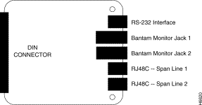
Table 1 Dual E1 NIC Connectors
The E1 NIC rear panel has two RJ-48C connectors one for each E1 span line, two Bantam jacks used for testing/troubleshooting, and an EIA/TIA-232 serial port.
The RJ-48C connectors provide a G.703/G.704 interface, which recovers clock and data from incoming E1 signals. The recovered data from the E1 NIC passes to the Dual E1/PRI NAC through the midplane connector. The midplane connector also allows the Dual E1/PRI NAC CPU to manage the E1 NIC. The E1 NIC does not have a software-driven component and is managed completely by the Dual E1/PRI NAC.
The RJ-48C connectors are dedicated to the E1 span lines that come into the chassis. The E1 span line cables are UTP 0.6 mm (22 AWG) 120 ohm impedance. The cables terminate on one end by the RJ-48C plug and on the other end as determined by country specific requirements. Each E1 span line provides thirty 64 Kbps B-channels that are multiplexed into the 2.048 Mbps rate.
Table 2 lists the supported pin assignments and functions for the RJ-48C interface of the E1 span lines.
Table 2 RJ-48C Pin Assignments
The two Bantam jacks are used for monitoring and troubleshooting equipment. These jacks (TX and RX) are passively coupled so that the monitoring equipment can be installed while the NIC is powered on, without causing errors.
The E1 NIC EIA/TIA-232 operator interface is an 8-pin connector that is configured as data terminal equipment (DTE).
Use the EIA/TIA-232 cable that is provided with the cards to connect with any of the following devices:
When connecting a PC to the EIA/TIA-232 operator interface, use the DB-25 female-to-male adapter that is provided with the card.
Note You must supply your own interface adapter if your application uses something other than a DB-25 connector.
Table 3 lists the supported functions and pin assignments of the EIA/TIA-232 interface.
Table 3 EIA/TIA-232 Pin Assignments
This section only discusses Dual E1/PRI network application card configuration prior to installation in the AS5100 chassis. Further configuration of the card is possible after the card is installed through the EIA/TIA-232 operator interface or by using management software.
Note For additional operator interface information, see the "E1/PRI Operator Interface" and "Dual E1/PRI NAC Operator Interface" sections in this document or your SNMP management software.
The Dual E1/PRI network application vard (NAC) is a surface mounted board that is designed to fit in the front portion of the AS5100 chassis and connects to the chassis midplane.
The chassis midplane provides connectors on the front for NACs and connectors on the back for NICs. The cards communicate through multiple data buses located in the midplane.
Note See the "Installation" section later in this document for information on the location of the midplane and of individual cards in the chassis.
The Dual E1/PRI NAC has the following features:
The Dual E1/PRI NAC allows signaling information to be communicated out of band over the PRI D-channels and thereby provides full 64 Kbps for the transmission of user data. The Dual E1/PRI NAC signaling uses a message based system to communicate signaling information for each channel and interfaces with and distributes calls either to the quad modem with a software update cards (QCBH-mdm) by way of the time division multiplex (TDM) bus or to a gateway card.
The Dual E1/PRI NAC standard configuration includes 4 MB of DRAM SIMM. Although 1 MB and 16 MB configurations are possible for customized applications, the DRAM SIMMs are not field upgradable.
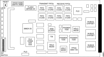
Ten DIP switches are located below the indicator LEDs on the Dual E1/PRI NAC (Figure 3). Of these, only DIP switches 1, 2, and 3 are functional at this time. DIP switches 1 and 2 are used to set the serial port rate of the EIA/TIA-232 interface. DIP switch 3 is used to enable or disable hardware flow control for the user interface port.
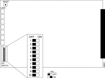
The DIP switches are numbered from 1 on the top to 10 on the bottom. Slide the switch to the right to turn it ON.
| Warning Make sure the DIP switches are set to your required specifications before installing the Dual E1/PRI NAC. See Table 4 for additional information. |
Table 4 Dual E1/PRI NAC.DIP Switches
|
||||||||||||||||||||||||||||||||||||||||||||||||||||||||||||
The operator interface for the E1/PRI NAC is accessed by attaching either a PC or a VT100 terminal to the EIA/TIA-232 serial port on the E1 NIC. From this interface, the operator is able to:
See "Dual E1 Network Interface Card" and "E1/PRI Operator Interface" sections for additional information on using the EIA/TIA-232 port features.
| Warning Check your PC or terminal documentation in order to determine the maximum serial port rate your equipment supports. Do this before installing the card so that you can make the proper DIP switch settings. |
Note If you are using a portable/notebook computer, note that many of the provided serial ports do not support data rates over 19.2 Kbps. If you are losing characters at 38.4 Kbps, drop to either 19.2 Kbps or to 9600 bps. Remember to change the DIP switches and set your PC to the specified baud rate.
The Dual E1/PRI NAC has seven indicator LEDs that are visible on the front panel. The LEDs are labeled as:
The Dual E1/PRI NAC LEDs provide startup, alarm (RAI, OOF, LOS, AIS, CRC errors, etc.), and physical layer state status (F0 through F6) information. See Table 5 for a brief description of the physical layer states, F0 through F6, as described in ITU-T I.431.
Note This section provides information on operating and alarm/event LED status information. For LED startup sequence and information see the "Installation" section later in this document.
The operating LED status can be viewed and monitored directly from the front panel. In addition, the LED status can be viewed from within your SNMP management software.
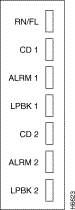
Table 5 E1 Physical Layer Status
Five of the seven LEDs on the Dual E1/PRI NAC provide the physical layer status and alarm information. They are: RN/FL, CAR 1, ALM 1, CAR 2, and ALM 2 (where CAR 1 and ALM 1 represent span line 1, and CAR 2 and ALM 2 represent span line 2).
To determine alarm and physical layer status check the LED condition and refer to Table 6.
Note Although the loopback 1/2 LEDs (LPBK 1/2) are operational and function during startup, they do not currently provide physical layer and alarm status information.
Table 6 Dual E1/PRI NAC Physical Layer Status LEDs
Through the AS5100 chassis midplane connector, the dual E1/PRI NAC has access to the following interfaces:
This section contains information on the AS5100 chassis configurations required when using the E1 cards, the procedures for installing the Dual E1 NIC and the Dual E1/PRI NAC in the chassis, and the LED startup sequence and diagnostics.
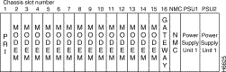
The AS5100 chassis (Figure 5) has 17 slots available for combinations of NAC and NIC cards. A network management card is typically located in slot 17. The NACs and NICs connect through the chassis midplane. The midplane provides multiple data buses that enable the NACs to communicate with each other and the NMC.
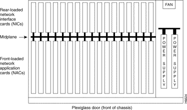
The Dual E1/PRI NAC and E1 NIC share the front and back slots and connect through the midplane. Currently, the E1/PRI chassis configuration requires that the E1 cards occupy chassis slot 1. Modems cards may be installed in slots 2 through 15; a gateway card, if used, must occupy slot 16; and the last slot contains the network management card, as shown in Figure 6. This chassis configuration provides compatibility with analog fax and analog modem devices from the Public Switched Telephone Network (PSTN).
The chassis arrangement (Figure 6) allows the Dual E1/PRI card to terminate analog calls to either an EIA/TIA-232 or a gateway card. Modem calls are routed to a pool of quad modems, using a round-robin distribution pattern.
Note See the "Call Processing and Routing" section later in this document for additional information on the round-robin distribution pattern.
This configuration supports a maximum of 60 analog calls out of a possible 61 for E1 NFAS. However, if a gateway card is used, then a maximum of 56 calls may be terminated with this configuration.
| Caution Always use ESD protection when working with electrostatic sensitive components. |
Step 2 With the E1 RJ-48C and EIA/TIA-232 interfaces facing out, slide the E1 NIC into the upper and lower card guides of the slot. Push firmly on the NIC until the midplane connector snaps into position in the chassis midplane.
Step 3 Tighten the thumbscrews that are attached to the E1 NIC rear panel. Pay careful attention to the alignment of the screws before tightening them. Problems could arise if the screws are not threaded properly.
Step 4 Attach the serial port cable (supplied with the card) and the E1 span line cables.
| Caution Always use ESD protection when working with electrostatic sensitive components. |
Cards may be inserted and removed while the chassis is powered-on. This is called hot-swapping. After the dual E1/PRI NAC is successfully inserted into a powered on chassis, the indicator LEDs will begin to flash in sequence during a power-up self test.
See the "Dual E1/PRI Network Application Card" section earlier in this document for specific DIP switch information.
Step 2 Unscrew and remove the cover panel from the desired slot at the front of the chassis. Save the panel and screws.
Step 3 Then, with the DIN connector facing the rear of the chassis and the LEDs facing the front, lift the ejector tabs while sliding the modem card into the slot's upper and lower card guides. Push firmly on the NAC until the rear connector is firmly positioned in the chassis midplane.
Step 4 Make sure the ejector clips are secure clips by pressing on the tabs until they click into position.
Step 5 After the DIN connector is plugged in and the E1/PRI NAC has power, the front panel LEDs light up in sequence during a series of diagnostic or power-up self tests. The power-up sequence may take over a minute to complete.
See the "LED Diagnostics" section later in this document for more information on these tests.
Step 6 Replace the front panel and tighten the captive screws that secure the panel to the chassis. Pay careful attention to the alignment of the screws before tightening them. Problems could arise if these screws are not threaded properly.
When the dual E1/PRI NAC is installed in a powered-on chassis, the boot code performs various initializations and power-up self-tests that are specific to the chipset. The sequence of events varies depending on whether the startup is a standard power-up or if new software is being downloaded. The LED sequence for these scenarios varies.
See the "Dual E1/PRI Network Application Card" section earlier in this document for additional information on the indicator LEDs.
During the standard power-up self-tests, all of the front panel LEDs light up in sequence: red, then amber, then green. Next the Run Fail (RN/FL) LED turns red then amber then green. This process takes about 20 seconds to complete.
Then, as the software is loaded from ROM to RAM, the RN/FL LED alternates between off and green. The time required to complete this portion of the LED sequence varies, depending on the amount of software being loaded.
When new software is being downloaded, the LED sequence during power-up is similar to the standard power-up sequence except that the time required varies according the amount of software being downloaded. At the end of the new software download, the card reboots and the normal LED sequence during power-up repeats.
After all the tests are performed and, if no failures are found, the RN/FL LED turns solid green, indicating that the card is properly installed and is ready for operation.
If a critical failure is detected, the RN/FL LED turns solid red or amber and the card reboots. A failure is considered critical if it affects execution. Any critical failure is likely to be a hardware problem. If one occurs, contact Cisco Systems Technical Support.
Take the following steps if critical failure occurs.
Step 2 If reseating the card does not resolve the critical failure, try re-downloading the software.
Step 3 If neither reseating the card in the midplane nor re-downloading the software resolves the critical failure, contact Cisco Systems Product Support.
Dual E1/PRI NACs and NICs are shipped in one of three ways, depending on the ordering specification:
This section provides information on managing the dual E1/PRI NAC through either the EIA/TIA-232 serial port interface using either a PC or VT100 terminal or through your SNMP management software. In addition, it describes the steps required to connect a VT100 terminal or PC to the E1 EIA/TIA-232 interface located on the dual E1 NIC in order to perform configuration and software download tasks on the Dual E1/PRI NAC.
For a detailed description of the menu structure that displays when a either PC or terminal connection is made via the EIA/TIA-232 serial port, refer to the "Dual E1/PRI NAC Operator Interface" section later in this document.
If you wish, a dedicated PC may be connected to the EIA/TIA-232 port. When performing configuration tasks, simply run a terminal emulation program to make your PC act like a terminal. Windows offers a terminal option, and many communications software programs allow you to establish a TTY connection.
An EIA/TIA-232 cable and a DB-25 female to DB-25 null modem are provided with your Dual E1/PRI package.
You must supply your own interface adapter if your hardware uses something other than a DB-25 connector.
See the "Dual E1 Network Interface Card" section earlier in this document for additional information on the EIA/TIA-232 serial port.
The default serial port rate at the E1/PRI NIC EIA/TIA-232 port is set at 38400 bps. The baud rate can be changed by adjusting the settings of DIP switches 1 and 2 on the dual E1/PRI NAC, as shown in Table 7.
See the "Dual E1/PRI Network Application Card" section earlier in this document for additional information on adjusting the DIP Switch settings.
Table 7 DIP Switch Serial Port Rate
The data format is 8 data bits, no parity, and 1 stop bit.
Note When performing a software download, we recommend that hardware flow control be enabled at the port. This requires that DIP switch 3 on the E1/PRI NAC be set to OFF (default setting) position.
This section provides information on the call signaling, processing, and routing functions of the dual E1/PRI NAC. Call signaling permits the Dual E1/PRI call to identify, setup, and tear down calls between the PTT and the QBCH-mdm cards in the chassis. Call processing involves establishing B-channel connections based on the signaling information received over the D-channels. Call routing is a scheme for sending the calls to the first available modem or appropriate device.
The primary function of the Dual E1/PRI NAC is to setup and tear down calls between the PTT and the QBCH-mdm cards. This is done through the D-channel which is dedicated to providing signaling for the B-channels (user channels).
The D-channel signaling software utilizes standard signaling software messages including Q.921 (layer 2) and Q.931 (layer 3). This makes it compatible with the European Telecommunications Standard (ETS) collection of standards for ICTR-4. PRI.
Call routing involves sending a call to another network application card (NAC) device and establishing the data path connection between the B-channel and the chosen TDM time slot for the call. The way a call is processed or routed is determined by the type of call, either analog or digital, and the available device configuration.
The Dual E1/PRI NAC communicates with the PTT over the 64 Kbps D-channel on each PRI span line. Setup and tear down information, including called number, bearer capability, and TDM time slot is sent to an application NAC over the packet bus. After a call is setup, the E1/PRI establishes a full duplex 64 Kbps connection between the PRI B-channel and the TDM time slot in the NAC that is being used for the call. While a call is established, the D-channel monitors only itself and the packet bus until it receives a tear down message. Other than establishing calls, the D-channel does not get involved with B-channel data.
When the NAC receives a dial in call, it interprets the Q.931 call setup messages and communicates the information to the appropriate NAC via the packet bus.
The E1/PRI is capable of handling setup circuit switched calls with an analog modem/fax in the Public Switched Telephone Network (PSTN). This type of circuit switched call, made between the PRI interface and an analog fax modem/fax on the Public Switched Telephone Network (PSTN), is not end-to-end ISDN.
A Q.931 message communicates the nature of the call to the Dual E1/PRI NAC and informs it when certain tones may be available on the B-channel. The ISDN cuts through the B-channel to let an audible ringing tone be sent from the far end. The Dual E1/PRI NAC, based on bearer capability (3.1 kHz audio or voice), routes the call to an available QBCH-mdm.
The Dual E1/PRI NAC in chassis slot 1 is configured to route analog modem calls. The dual E1/PRI NAC recognizes and routes incoming analog calls to a pool of modems and/or a gateway card.
Note For additional information on chassis configuration requirements, see the "Installation" section earlier in this document.
The D-channel Q.931 setup message contains setup information that identifies the type of call. Incoming analog calls are routed to a modem or a gateway card. The QBCH-mdm is the default setting for analog calls.
Typically, incoming analog calls that originate from a modem are either speech or 3.1 kHz audio. Sometimes an incoming digital originated call will be transmitted as speech or as 3.1 kHz audio. This may occur when the originated digital call requests speech or 3.1 kHz audio in order to pass the data at a lower tariff rate.
Calls to the Dual E1/PRI NAC are routed based on call type, either analog or digital, and chassis device configuration.
Incoming call Q.931 setup messages are used to direct the call to the appropriate device or reject the call if the call type is not supported. Analog calls, speech or 3.1 kHz audio, are routed to the modem pool.
The Dual E1/PRI NAC in chassis slot 1 routes analog calls to a configured pool of modem cards. Incoming calls are distributed in a round-robin manner starting with the lowest idle modem slot/channel.
In the following example, there is a dual E1/PRI NAC in chassis slot 1 and 12 modems starting in slot 2.
Note If the modem rejects an incoming call, the Dual E1/PRI NAC will try other modems in the pool. If none of the modems respond, the call is dropped.
Table 8 First Call Routed to Lowest Slot/Channel Modem (2/1)
Table 9 Second Call Routed to Next Lowest Idle Slot/Channel Modem (2/4)
Table 10 Third Call Routed to Next Lowest Idle Slot/Channel Modem (3/1)
Connecting a VT100 terminal or a PC using a terminal emulation program to the EIA/TIA-232 operator interface port on the dual E1 NIC allows an operator to configure and manage the dual E1/PRI NAC via menu-driven screens. After the PC or terminal is connected, press the Return key to display the operator interface main menu that follows.
Note A remote operator can dial in to a modem connected to the EIA/TIA-232 interface and configure the E1/PRI NAC. After the modems have connected, press the Return key to display the following main menu on the remote terminal screen.
To select an option from the main menu, type the number of the desired selection and press Return. At any point in the menu structure, press Esc to return to the previous menu.
When you select the Command option from the main menu, the following menu appears. This menu provides command options to perform specific functions on the individual E1 span lines and B-channels.
Reset to Highest Priority Timing Source. Select option 1 to reset the E1/PRI NAC timing source to the next highest priority. The possible choices are span line 1 or span line 2. The reset sequence may take more than a minute to complete.
Reset PRI NAC. Select option 2 to reset the E1/PRI NAC and restore the factory configuration. This action takes place immediately and does not prompt for confirmation.
Disconnect Call on Span Line 1<2> B-Channel(s). Selecting this option allows an operator to disconnect an individual B-channel or a range of B-channels. Type the desired entries, separated by a comma. Use a hyphen to indicate a range of B-channels.
Force TDM Bus Mastership on Card. Selecting this option allows an operator to manage the TDM bus via the E1/PRI NAC.
The status menu provides information on the current status of the cards in the chassis, the configuration, and alarm event information. Select main menu option 2, status, to display the status menu.
The eight status options report on various status conditions on the E1/PRI NAC and E1 span line(s) and alarms or events taking place. The displayed status is a snapshot of the events and/or conditions at the time the operator requests the status report.
Power-up Self-test Status. During power-up, the E1/PRI NAC software performs a variety of tests to ensure proper-operation of the hardware. Select option 1 from the status menu to display the test results.
The possible Power-up self-test status results are:
Card Status. Select status menu option 2 to view the current timing source, the type of NIC installed with the E1/PRI NAC, the slot in which the E1/PRI NAC is installed, and the size of the installed DRAM and Flash ROM. If the timing source is set to either span line 1 or 2, then the EI/PRI is a slave.
Chassis Slot Device Configuration Status. Select Status menu option 3 to obtain information on the current chassis slot device configuration. The possible device type configurations are None (no device installed), dual PRI (Dual E1/PRI card), or QBCH-mdm (Quad B-Channel Modem).
Quad B-channel/Modem Device Status. Select option 4 to monitor the status of the installed modems (QBCH-mdm). Each modem slot/channel indicates whether a modem is available (AVAIL); a modem is not available (Un-Avail); or a modem is currently active and not available (In use).
Span Line 1<2> DS0 Status. Select Status menu options 6 or 8 to view a snapshot of DS0 status for span lines 1 or 2.
The possible DS0 Status options are:
Alarm/Event Status. Select status menu options 7 or 9 to view a snapshot of alarm/event status for each span line.
The following list describes each status condition reported on this screen.
When you select card configuration, option 3 from the main menu, the following menu appears. The configuration options available from this screen pertain to the E1/PRI NAC as a whole. From the card configuration menu the default configuration can be changed, saved, and restored. In addition, the timing source priority and the chassis slot configuration can be assigned from this menu.
To return to the card configuration menu from one of the card configuration submenus, press Esc.
Save Current Configuration to NVRAM. To save changes you made to the default configuration of the E1/PRI NAC, select option 1. This will save the new configuration to NVRAM. You will be prompted to confirm the operation.
Restore NVRAM Configuration. If you made and saved changes to the NVRAM settings, and you wish to reset the E1/PRI NAC to its previous settings, select option 2. You will be prompted to confirm the operation.
Note If you made changes to the NVRAM settings and selected option 1 Save Current Configuration to NVRAM, you cannot restore the previous NVRAM configuration.
Restore Default Configuration Select option 3 to reload all factory configuration defaults. You will be prompted to confirm the operation.
Timing Source Priority Assignment. A number from 1 (highest priority) to 2 (lowest priority) is assigned to the timing sources. The timing source with the highest priority clocks data on the span line(s). Any timing source can be disabled by assigning a priority of 0. If not disabled, two or more timing sources cannot be assigned the same priority. Priority assignment of timing sources allows switching to the next highest timing source if the current source fails.
The timing source does not switch unless a failure is detected on the current choice. For example, if the primary timing source fails, the secondary timing source takes over. The secondary source remains active as long as it does not fail, even if the primary source returns. From the Command Menu, select Reset to Highest Priority Timing Source. The primary timing source once again becomes active. See a full description earlier in this section.
Table 11 presents a summary of the options and defaults for the timing source priority.
Table 11 Timing Source Priority
Chassis Slot Device Configuration Selecting this option allows the operator to assign device types to chassis slot numbers. Each slot on the chassis is assigned a number from 1 to 16. To assign a device type to a specific slot, use the following numbers:
Note If you receive the error message: "Ring No Answer," check the chassis slot device configuration status to ensure that the modem settings on screen reflect the placement in the chassis.
When you select span line 1/2 configuration. from the main menu, the following menu appears. To return to the span line 1/2 configuration menu from one of these submenus, press Esc.
Table 12 summarizes the options and defaults for parameters configurable per span line.
Table 12 Parameters Configurable per E1 Span Line
Framing Mode. Allows an operator to specify the framing format to use. Currently, G.704 with CRC-4 is supported for span line 1/2.
Line Coding. Allows an operator to select a line coding scheme for Span line 1/2. A line coding scheme ensures a sufficient density of 1's in the bit stream, required by the E1 standard for clock synchronization. High density bipolar-3 (HDB3) is the only line coding supported for E1/PRI NAC service.
Locally Initiated Remote Loopback. Allows an operator to enable or disable the remote loopback mode for span lines 1/2. This is a troubleshooting utility that loops back DS0 32 upon itself. It is initiated at the EIA/TIA-232 local interface. The operator must initiate this feature locally at the user interface. While in loopback mode, the LPBK LED for the appropriate E1 line is green. The normal state is disabled.
Jitter Attenuation. The E1 NIC hardware provides a 193-bit frame buffer to compensate for low frequency jitter with the synchronization to the E1 network. This buffer can be placed in either the receive or transmit data path. The default setting is the receiver.
Span Line 1/2 Switch Type. The switch type can be set to accommodate the Euro ISDN ETS ICTR-4 switch standard.
Idle Byte Pattern. E1 equipment requires a sufficient number of 1's in the bit stream to derive clock synchronization. This parameter can be set to send to the PTT on idle B-channels. The parameter is configurable so that it can be adjusted to satisfy the 1's density required by the PTT. Use a byte in the hexadecimal ranges from 00 to FF.
The software fault manager event logging provides a record of software fault events. The event logging feature may either be enabled or disabled. In addition, two types of displays, either an online or historical record, can be maintained.
Event Logging. Selecting the software fault manager event logging option allow the operator to enable or disable the software fault manager event logging program. The choices are 1 to enable or 2 to disable the event logging feature.
Online Display. Selecting this option allows the operator to enable or disable the online display of software faults. The choices are 1 to enable or 2 to disable the online display feature.
History Setting. Selecting this option allows the operator to enable or disable the software fault manager history setting. The choices are 1 to enable or 2 to disable the history setting feature.
Table 13 lists the E1/PRI technical specifications.
|
E1/PRI Technical Specifications
Cisco Information Online (CIO) is Cisco Systems' primary, real-time support channel. Maintenance customers and partners can self-register on CIO to obtain additional content and services.
Available 24 hours a day, 7 days a week, CIO provides a wealth of standard and value-added services to Cisco's customers and business partners. CIO services include product information, software updates, release notes, technical tips, the Bug Navigator, configuration notes, brochures, descriptions of service offerings, and download access to public and authorized files.
CIO serves a wide variety of users through two interfaces that are updated and enhanced simultaneously—a character-based version and a multimedia version that resides on the World Wide Web (WWW). The character-based CIO (called "CIO Classic") supports Zmodem, Kermit, Xmodem, FTP, Internet e-mail, and fax download options, and is excellent for quick access to information over lower bandwidths. The WWW version of CIO provides richly formatted documents with photographs, figures, graphics, and video, as well as hyperlinks to related information.
You can access CIO in the following ways:
For a copy of CIO's Frequently Asked Questions (FAQ), contact cio-help@cisco.com. For additional information, contact cio-team@cisco.com.
Note If you are a network administrator and need personal technical assistance with a Cisco product that is under warranty or covered by a maintenance contract, contact Cisco's Technical Assistance Center (TAC) at 800 553-2447, 408 526-7209, or tac@cisco.com. To obtain general information about Cisco Systems, Cisco products, or upgrades, contact 800 553-6387, 408 526-7208, or cs-rep@cisco.com.
![]()
![]()
![]()
![]()
![]()
![]()
![]()
![]()
Posted: Tue Sep 2 10:31:19 PDT 2003
All contents are Copyright © 1992--2003 Cisco Systems, Inc. All rights reserved.
Important Notices and Privacy Statement.