|
|

This procedure discusses the field replacement of the MAS-20 muffin fan.
| Caution This procedure is recommended only for experienced technicians and engineers because access to the chassis interior is required. Before beginning this procedure, it is strongly advised that you read through the entire document. If you have any doubts about your ability to perform any part of this procedure, contact a service representative for further guidance. |
| Warning Before accessing the chassis interior and removing any cards, turn off power to the chassis and unplug the power cord. Use extreme caution around the chassis since potentially harmful voltages are present. |
The replacement part for this procedure is the MAS-20 muffin fan. The MAS-20 is recommended for use in the M and C chassis. The M chassis uses two of the MAS-20 fans, and the C chassis uses one. The MAS-20 fan operates with +12 volts direct current (DC) supplied by the M or C chassis power supply.
Electrostatic discharge damage (ESD) occurs when electronic printed circuit cards are improperly handled and can result in complete or intermittent failures. ESD can impair electronic circuitry and equipment. Always follow ESD prevention procedures when removing and replacing cards.
Following are steps for handling printed circuit cards:
Step 2: Connect the strap to an unpainted chassis frame surface or another proper grounding point or surface to safely channel unwanted ESD voltages to ground (see Figure 1).
Step 3: Use the ejectors to remove the card. Handle the card by its sides. Place the card on an antistatic surface or in a static shielding bag. To prevent further damage to the card by ESD voltages, defective cards must remain in the static shielding bag when returned for repair or replacement.
Step 4: Handling the new card by its edges only, insert it into the chassis. Avoid contact between the card and clothing. The wrist strap only protects the card from ESD voltages on the body; ESD voltages on clothing can still damage the card.
Use an ohmmeter to check the ESD wrist strap to ensure that the resistor is providing proper ESD protection. For safety, the measurement should be in the range 1 to 10 Mohms.
Refer to the following procedures and accompanying illustrations to access and remove the suspect fan and to install the new MAS-20 fan. Before you start the installation procedure, read through this entire document to familiarize yourself with the required tasks.
| Warning Before accessing the chassis interior, turn off power to the chassis and unplug the power cord. High voltages may exist in or near the power supply. Use extreme caution when working near the power supply. Attach appropriate ESD protection before beginning the replacement procedure. |
Once you have taken the necessary ESD precautions, you can proceed with the installation of the new MAS-20 fan.
The following items are required for installation of the MAS-20 fan:
n Two Phillips screwdrivers, No. 1 and No. 2
n One medium flat-blade screwdriver
n One pair of medium size pliers
n Needle nose pliers, medium size
n Digital multimeter or voltmeter (DMM or DVM)
Note: The following procedures differ for the M and C chassis; refer to the appropriate section depending upon your chassis type.
Following is the procedure for accessing the M chassis:
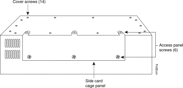
Step 2: Locate the three screws that secure the card cage access panel. Use the flat-blade screwdriver to turn each of these screws 1/4 to 1/2 turn counterclockwise until the screws pop up.
Step 3: Loosen the three screws at the bottom edge of the card cage cover (do not remove these screws completely). Carefully remove the cover and set it aside.
Proceed to "Removing the Suspect Power Supply."
Following is the procedure for accessing the C chassis:
Step 2: Orient the chassis so that the back (the side with the ports) is on your left, and the front (with the LED) of the chassis is on your right. This will place the power supply on the side of the chassis closest to you after you remove the cover.
Step 3: Pull the front of the cover to the right while securing the back of the chassis with your left hand. Pull slowly and carefully; the fit is snug.
| Caution Several cables are located close to the interior of the C chassis cover. Avoid damage to these cables by ensuring that they do not impede the cover as you remove it. |
Step 4: Pull the cover to the right until the power supply and the card cage are completely exposed, but do not pull the cover completely off.
Proceed to "Removing the Suspect Power Supply."
Note: This procedure is only necessary if the cause of the fan failure is undetermined. If the muffin has definitely failed, proceed to the section "Replacing the MAS-20."
Two common symptoms indicate a muffin fan failure and both will help define the cause of the failure. The most obvious symptom is a loud whining or grinding sound coming from the fan. This sound typically indicates a bearing failure inside the fan.
The second failure symptom concerns the fan's functionality, which has two parts: the failure of the fan itself or the failure of the +12 volt power supply that powers the fan. To distinguish one from the other, the +12 volt power supply must be checked with a digital multimeter or voltmeter (DMM or DVM) set for DC voltage. The yellow wire between the backplane and the fan supplies +12 volts (see Figure 4).
The procedure for testing the +12 volt supply is as follows:
Step 2: With the red probe of the DMM, touch the point where the yellow wire meets the backplane (see position 7 in Figure 4).
| Warning To avoid a short circuit and electrical shock hazard, exercise great care with the DMM probes. A short circuit could cause damage to all cards and the power supply, so do not touch more than one wire with one probe. |
The voltage reading on the DMM should be +12 volts (+/-5%). If the voltage is too low, the fan will turn more slowly; if it's too high the fan could burn out and cause other problems in the system as well. A complete power supply failure is indicated by a voltage measurement of zero.
Note: If (in the M chassis only) the +12 volt measurement is correct, fan failure can be verified by attaching the connector of the second fan to the connector of the suspect fan. If the second fan works, the failure is in the suspect fan (and the +12 volt power supply is fine). This will not work with the C chassis, which has one fan.
If the +12 volt measurement is nominal, proceed to the appropriate section:
n "Replacing the MAS-20 in the M Chassis"
n "Replacing the MAS-20 in the C Chassis"
Note: If the +12 volt measurement is incorrect or is zero, contact a service representative to obtain a replacement power supply.
Following are the procedures for replacing the MAS-20 in the M and C chassis. The procedures differ for both chassis. Use the procedure that applies to your chassis type.
Following are the procedures for replacing the MAS-20 in the M chassis:
Step 2: Disconnect the white connector of the fan that has failed. Cut the nylon cable tie securing the fan wires. Do not cut the fan wires.
Note: The wires from the fan are red and blue, while the wires from the backplane are yellow and black. Note their relationship and alignment for reconnection.
Step 3: Look at the rear panel of the chassis (exterior) and locate the four screws securing the grill and fan to the chassis rear panel.
Step 4: Use the No. 2 Phillips screwdriver to remove the two bottom screws that secure the grill and fan to the chassis.
Note: The newer MAS-20 fans have pem nuts attached to the four fan screw holes. The pliers or adjustable wrench (in steps 5 and 6) are not necessary if the fan has these pem nuts attached; the fan can be removed with only a No. 2 Phillips screwdriver.
Step 5: Use the pliers or adjustable wrench to hold the nut (that secures one of the top two fan screws on the chassis interior) and remove the screw (on the chassis exterior) with the No. 2 Phillips screwdriver.
Step 6: Remove the remaining nut and screw (as in step 5) and set all removed hardware aside.
Step 7: Completely remove the fan and grill from the chassis.
Following is the procedure for installing the new MAS-20 in M chassis:
Step 2: Remove the new fan from its packaging.
Step 3: Examine the new fan and locate the arrow (indicating direction of airflow) that is embossed on the fan casing. Also note the position of the red an blue wires coming out of the fan.
Step 4: Orient the fan so that the arrow is pointing toward the rear of the chassis (toward you), and the wires are at the top of the fan.
Step 5: Position the grill over the fan opening on the rear panel exterior.
Step 6: Install the screws that secure the fan to the chassis rear panel (start with the top two screws) by inserting the screw through the grill, through the screw hole in the rear panel, and into the pem nut on the fan.
Step 7: Locate the fan connectors coming from the backplane and the new muffin fan.
Step 8: Align the red wire from the fan connector with the yellow wire from the backplane connector and attach the two connectors.
Note: The fan connectors are keyed and this alignment is included as a precaution in case the new fan is wired incorrectly.
Step 9: Use cable ties to bundle the fan wires and connector away from the opening of the fan. Do not stress the wires at either end.
Proceed to the section "Testing the New MAS-20 Muffin Fan in the M or C Chassis."
Following are the procedures for replacing the MAS-20 in the C chassis:
Following is the procedure for removing the suspect MAS-20 from the C chassis:
Note: The wires from the fan are red and blue, while the wires from the backplane are yellow and black. Note their relationship and position for reconnection.
Step 2: Disconnect the white fan connector and cut the nylon cable ties securing the fan wires. Do not cut the fan wires.
Note: The newer MAS-20 fans have pem nuts attached over the four screw holes; therefore, the pliers or wrench (mentioned in step 3) may not be necessary. The newer MAS-20 fans do not require the mounting plates and attach directly to the chassis rear panel.
Step 3: Locate and remove the four screws securing the fan and mounting plate to the chassis rear panel. Use the pliers or adjustable wrench (if necessary) to hold the top two nuts while removing the screws with the No. 2 Phillips screwdriver.
Step 4: Completely remove the fan and mounting plate from the chassis.
Following is the procedure for installing the new MAS-20 in C chassis:
Step 2: Position the chassis so the rear panel is facing you. This will place the fan opening to your right.
Step 3: Examine the new fan and locate the arrow (indicating direction of airflow) embossed on the fan casing; also locate the wires coming out of the fan.
Step 4: Facing the rear chassis panel, position the fan so that the arrow is pointing toward the rear of the chassis (toward you), and the fan wires are on the left side of the fan.
Step 5: Install the screws that secure the fan to the chassis rear panel (start with the top two screws).
Step 6: Locate the fan connectors from the backplane and the new fan.
Step 7: Align the red wire from the fan connector with the yellow wire from the backplane connector and attach the two connectors.
Note: The fan connectors are keyed and this alignment is included as a precaution in case the new fan is wired incorrectly.
Step 8: Use cable ties to bundle the fan wires away from the opening of the fan. Do not stress the wires at either end.
Proceed to the section "Testing the New MAS-20 Muffin Fan in the M or C Chassis."
| Warning High voltages may exist in or near the power supply; use extreme caution when working with the power supply. |
After you install the new MAS-20 muffin fan in your chassis, test the installation by turning the power on and verifying that the fan is turning. Also check that the direction of airflow is from the chassis interior to the exterior. The fan new should operate quietly and emit no noise other than the sound of air flowing through it.
Note: Backward airflow indicates that the leads on the fan connectors have been reversed. Any other noises may indicate a defective MAS-20 fan.
After successfully testing the fan installation, turn off the power, unplug the power cable, and proceed as follows:
n M chassis only—Replace the top cover and the card cage cover on the side of the chassis using the removed screws (see Figure 2).
n C chassis only—Reattach the card clamps at either end of the card cage and replace the top chassis cover using the removed screws (see Figure 3).
![]()
![]()
![]()
![]()
![]()
![]()
![]()
![]()
Posted: Thu Nov 6 16:15:36 PST 2003
All contents are Copyright © 1992--2003 Cisco Systems, Inc. All rights reserved.
Important Notices and Privacy Statement.