|
|

Table Of Contents
ISDN BRI S/T WAN Interface Cards
Prerequisites for Connecting an ISDN BRI S/T WIC to a Network
Connecting an ISDN BRI S/T WIC to a Network
ISDN BRI U WAN Interface Cards
Prerequisites for Connecting an ISDN BRI U WIC to a Network
Connecting an ISDN BRI U WIC to a Network
ISDN BRI S/T Leased-Line WAN Interface Card
ISDN BRI S/T Leased-Line WICs Overview
ISDN BRI S/T Leased-Line WIC LEDs
Prerequisites for Connecting an ISDN BRI S/T Leased-Line WIC to a Network
Connecting an ISDN BRI S/T Leased-Line WIC to a Network
Obtaining Documentation, Obtaining Support, and Security Guidelines
ISDN BRI WAN Interface Cards
Revised: 6/7/07, OL-12844-01Overview
This document describes ISDN BRI WAN interface cards (WICs) and how to connect ISDN BRI WICs to a network. It contains the following sections:
•
ISDN BRI S/T WAN Interface Cards
•
•
•
ISDN BRI S/T WAN Interface Cards
This section describes ISDN BRI S/T WICs and how to connect ISDN BRI S/T WICs to a network and contains the following sub sections:
•
•
ISDN BRI S/T WICs Overview
The ISDN BRI S/T WICs connect to an ISDN network through an external NT1 device. This interface is also known as an S/T interface. There are three ISDN BRI S/T WICs:
Note
•
•
•
Warning
Figure 44 WIC36-1B-S/T Front Panel
Figure 45 WIC-1B-S/T Front Panel
Figure 46 WIC-1B-S/T-V3 Front Panel
ISDN BRI S/T WIC LEDs
The ISDN BRI S/T WIC LEDs are shown in Figure 44, Figure 45, and Figure 46. The functions of the LEDs are described in Table 9.
Prerequisites for Connecting an ISDN BRI S/T WIC to a Network
Before connecting a WIC to the network, ensure that the WIC is installed in the router, the equipment is properly grounded, and you have the proper cables for connecting the WIC to the network. This section describes the preparation necessary before connecting an ISDN BRI S/T WIC to the network.
Installing a Cisco ISDN BRI S/T WAN Interface Card
Install the Cisco WIC according to the instructions in Installing Cisco Interface Cards in Cisco Access Routers.
Note
Grounding
Ensure that the equipment you are working with is properly grounded. For instructions on grounding your WIC, refer to Installing Cisco Interface Cards in Cisco Access Routers.
Cables
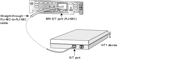
Use a straight-through RJ-48C-to-RJ-48C BRI cable (not included) to connect an ISDN BRI S/T WIC to a network.
Setting Jumpers on ISDN BRI WICs
The WIC-1B-S/T, WIC-1B-S/T-V3, and WIC-1B-U interface cards do not have termination jumpers.
Note
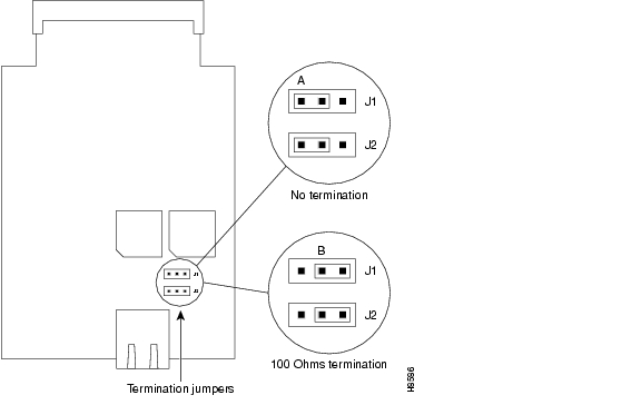
The WIC36-1B-S/T, WIC36-1B-U, CPAWIC36-1B-S/T, and CPAWIC36-1B-U interface cards have two termination jumpers, labeled J1 and J2. Before installing a WIC36-1B-S/T, WIC36-1B-U, CPAWIC36-1B-S/T, or CPAWIC36-1B-U interface card, ensure that the termination jumpers are set appropriately for your installation.
The jumpers are factory-configured in the B position. Keep the jumpers in this position to use the ISDN BRI WIC in a point-to-point connection or as the last device on the line of a passive-bus connection. Set the termination jumpers to the A position to use the ISDN BRI WIC in a passive-bus connection in which it is not the last device on the line. The jumpers are shown in Figure 47.
Figure 47 Jumper Locations on the Older ISDN BRI WIC
Connecting an ISDN BRI S/T WIC to a Network
Warning
Warning
To connect an ISDN BRI S/T WIC to a network, follow these steps:
Step 1
Warning
Step 2
Step 3
Figure 48 Connecting an ISDN BRI S/T WIC to an NT1 Device
Step 4
Step 5
Step 6
ISDN BRI U WAN Interface Cards
This section describes how to connect ISDN BRI U WICs to a network and contains the following sections:
•
•
ISDN BRI U WICs Overview
The 1-port ISDN BRI U WICs contain an integrated NT1 device. This interface is also known as a U interface. There are three ISDN BRI U WICs:
Note
•
•
•
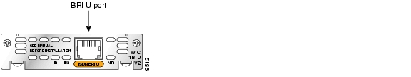
Figure 49 WIC36-1B-U Front Panel
Figure 50 WIC-1B-U Front Panel
Figure 51 WIC-1B-U-V2 Front Panel
ISDN BRI U WIC LEDs
The ISDN BRI U WIC LEDs are shown in Figure 49, Figure 50, and Figure 51. The functions of the LEDs are described in Table 10.
Prerequisites for Connecting an ISDN BRI U WIC to a Network
Before connecting a WIC to the network, ensure that the WIC is installed in the router, the equipment is properly grounded, and you have the proper cables for connecting the WIC to the network. This section describes the preparation necessary before connecting an ISDN BRI U WIC to the network.
Installing a Cisco ISDN BRI S/T WAN Interface Card
Install the Cisco WIC according to the instructions in Installing Cisco Interface Cards in Cisco Access Routers.
Note
Grounding
For instructions on grounding your WIC, refer to Installing Cisco Interface Cards in Cisco Access Routers.
Cables
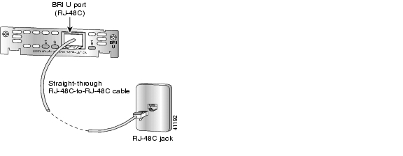
Use a straight-through RJ-48C-to-RJ-48C BRI cable (not included) to connect an ISDN BRI U WIC to a network.
Setting Jumpers on ISDN BRI WICs
The WIC-1B-S/T and WIC-1B-U interface cards do not have termination jumpers. The WIC36-1B-S/T, WIC36-1B-U, CPAWIC36-1B-S/T, and CPAWIC36-1B-U interface cards have two termination jumpers, labeled J1 and J2. Before installing a WIC36-1B-S/T, WIC36-1B-U, CPAWIC36-1B-S/T, or CPAWIC36-1B-U interface card, ensure that the termination jumpers are set appropriately for your installation.
The jumpers are factory-configured in the B position. Keep the jumpers in this position to use the ISDN BRI WIC in a point-to-point connection or as the last device on the line of a passive-bus connection. Set the termination jumpers to the A position to use the ISDN BRI WIC in a passive-bus connection in which it is not the last device on the line. The jumpers are shown in Figure 52.
Figure 52 Jumper Locations on the Older ISDN BRI WIC
Connecting an ISDN BRI U WIC to a Network
Warning
Warning
To connect an ISDN BRI U WIC to a network, follow these steps:
Step 1
Warning
Step 2
Step 3
Figure 53 Connecting an ISDN BRI U WIC to an ISDN Wall Jack
Step 4
Step 5
ISDN BRI S/T Leased-Line WAN Interface Card
This section describes how to connect ISDN BRI S/T leased-line WICs to a network and contains the following sections:
•
•
•
•
ISDN BRI S/T Leased-Line WICs Overview
The 1-port ISDN BRI S/T leased-line WIC (WIC-1B-S/T-LL) provides a single B channel operating in leased-line mode at 64-kbps. (See Figure 54.)
Figure 54 WIC-1B-S/T-LL Front Panel
ISDN BRI S/T Leased-Line WIC LEDs
The ISDN BRI S/T leased-line WIC LEDs are shown in Figure 54. The functions of the LEDs are described in Table 11.
Table 11 ISDN BRI S/T Leased-Line WIC LEDs
B1
ISDN connection on B1 channel when blinking.
B21
ISDN connection on B2 channel (not used).
OK
ISDN port has established a connection with the central office switch (D channel).
1 Always off for 64 kbps, which is available on B1 only.
Prerequisites for Connecting an ISDN BRI S/T Leased-Line WIC to a Network
Before connecting a WIC to the network, ensure that the WIC is installed in the router, the equipment is properly grounded, and you have the proper cables for connecting the WIC to the network. This section describes the preparation necessary before connecting an ISDN BRI U WIC to the network.
Installing a Cisco ISDN BRI S/T WAN Interface Card
Install the Cisco WIC according to the instructions in Installing Cisco Interface Cards in Cisco Access Routers.
Grounding
Ensure that the equipment you are working with is properly grounded. For instructions on grounding your WIC, refer to Installing Cisco Interface Cards in Cisco Access Routers.
Cables
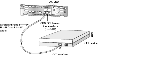
Use a straight-through RJ-48C-to-RJ-48C BRI cable (not included) to connect an ISDN BRI S/T leased-line WIC to a network.
Connecting an ISDN BRI S/T Leased-Line WIC to a Network
Warning
Warning
To connect an ISDN BRI S/T leased-line WIC to a network, follow these steps:
Step 1
Step 2
Step 3
Figure 55 Connecting the ISDN BRI S/T Leased Line Card to an NT1 Device
Step 4
Step 5
Step 6
Supported Platforms
For a list of the platforms supported by a Cisco interface card refer to Platform Support for Cisco Interface Cards.
Finding Support Information for Platforms and Cisco IOS Software Images
Use Cisco Feature Navigator to find information about platform support and Cisco IOS software image support. Access Cisco Feature Navigator at http://www.cisco.com/go/fn. You must have an account on Cisco.com. If you do not have an account or have forgotten your username or password, click Cancel at the login dialog box and follow the instructions that appear.
Related Documentation
Related documentation is available on Cisco.com or on the Product Documentation DVD. For more information, see the "Obtaining Documentation, Obtaining Support, and Security Guidelines" section.
•
•
•
•
Obtaining Documentation, Obtaining Support, and Security Guidelines
For information on obtaining documentation, obtaining support, providing documentation feedback, security guidelines, and also recommended aliases and general Cisco documents, see the monthly What's New in Cisco Product Documentation, which also lists all new and revised Cisco technical documentation, at:
http://www.cisco.com/en/US/docs/general/whatsnew/whatsnew.html
Any Internet Protocol (IP) addresses used in this document are not intended to be actual addresses. Any examples, command display output, and figures included in the document are shown for illustrative purposes only. Any use of actual IP addresses in illustrative content is unintentional and coincidental.
© 2007 Cisco Systems, Inc. All rights reserved.
![]()
![]()
![]()
![]()
![]()
![]()
![]()
![]()
Posted: Tue Jan 29 17:41:53 PST 2008
All contents are Copyright © 1992--2008 Cisco Systems, Inc. All rights reserved.
Important Notices and Privacy Statement.