|
|

Product Numbers: PWR-2691-DC-U=
This document describes how to replace the DC power supply in a Cisco 2691 router.
This document is intended for the power supply installer, who should be familiar with electronic circuitry and wiring practices and have experience as an electronic or electromechanical technician. Use this document in conjunction with the Cisco 2600 Series Hardware Installation Guide and the Regulatory Compliance and Safety Information document for your router.
This document contains the following sections:
 |
Note Means reader take note. Notes contain helpful suggestions or references to additional information. |
 |
Caution Means reader be careful. In this situation, you might do something that could result in equipment damage or loss of data. |
Follow these guidelines to ensure general safety:
 |
Warning Only trained and qualified personnel should be allowed to install, replace, or service this equipment. To see translations of the warnings that appear in this publication, refer to the Regulatory Compliance and Safety Information document that accompanied this device. |
|
Warning To prevent personal injury or damage to the chassis, never attempt to lift or tilt the chassis using the handles on modules (such as power supplies, fans, or cards); these types of handles are not designed to support the weight of the unit. To see translations of the warnings that appear in this publication, refer to the Regulatory Compliance and Safety Information document that accompanied this device. |
|
Warning Ultimate disposal of this product should be handled according to all national laws and regulations. To see translations of the warnings that appear in this publication, refer to the Regulatory Compliance and Safety Information document that accompanied this device. |
|
Warning Before working on equipment that is connected to power lines, remove jewelry (including rings, necklaces, and watches). Metal objects will heat up when connected to power and ground and can cause serious burns or weld the metal object to the terminals. To see translations of the warnings that appear in this publication, refer to the Regulatory Compliance and Safety Information document that accompanied this device. |
|
Warning Before working on a chassis or working near power supplies, unplug the power cord on AC units; disconnect the power at the circuit breaker on DC units. To see translations of the warnings that appear in this publication, refer to the Regulatory Compliance and Safety Information document that accompanied this device. |
|
Warning Do not work on the system or connect or disconnect cables during periods of lightning activity. To see translations of the warnings that appear in this publication, refer to the Regulatory Compliance and Safety Information document that accompanied this device. |
|
Warning Before opening the chassis, disconnect the telephone-network cables to avoid contact with telephone-network voltages. To see translations of the warnings that appear in this publication, refer to the Regulatory Compliance and Safety Information document that accompanied this device. |
|
Warning This product relies on the building's installation or power supply for short circuit (overcurrent) protection. Ensure that a Listed and Certified fuse or circuit breaker no larger than 60 VDC, 15A is used on all current-carrying conductors. To see translations of the warnings that appear in this publication, refer to the Regulatory Compliance and Safety Information document that accompanied this device. |
|
Warning This equipment has been designed for connection to TN and IT power systems. To see translations of the warnings that appear in this publication, refer to the Regulatory Compliance and Safety Information document that accompanied this device. |
|
Warning To avoid electric shock, do not connect safety extra-low voltage (SELV) circuits to telephone-network voltage (TNV) circuits. LAN ports contain SELV circuits, and WAN ports contain TNV circuits. Some LAN and WAN ports both use RJ-45 connectors. Use caution when connecting cables. To see translations of the warnings that appear in this publication, refer to the Regulatory Compliance and Safety Information document that accompanied this device. |
|
Warning This equipment must be grounded. Never defeat the ground conductor or operate the equipment in the absence of a suitably installed ground conductor. Contact the appropriate electrical inspection authority or an electrician if you are uncertain that suitable grounding is available. To see translations of the warnings that appear in this publication, refer to the Regulatory Compliance and Safety Information document that accompanied this device. |
|
Warning Use copper conductors only. To see translations of the warnings that appear in this publication, refer to the Regulatory Compliance and Safety Information document that accompanied this device. |
|
Warning When installing or replacing the unit, the ground connection must always be made first and disconnected last. To see translations of the warnings that appear in this publication, refer to the Regulatory Compliance and Safety Information document that accompanied this device. |
Refer to the Regulatory Compliance and Safety Information document that accompanied this device.
Follow these guidelines when working on equipment powered by electricity:
|
Caution To avoid damaging electrostatic discharge (ESD)-sensitive components, ensure that you have discharged all static electricity from your body before opening the chassis. Before performing procedures described in this document, review the next section, "Safety Recommendations." |
Electrostatic discharge (ESD) can damage equipment and impair electrical circuitry. It occurs when electronic printed circuit cards are improperly handled and can result in complete or intermittent failures. Always follow ESD prevention procedures when removing and replacing cards. Ensure that the router chassis is electrically connected to earth ground. Wear an ESD-preventive wrist strap, ensuring that it makes good skin contact. Connect the clip to an unpainted surface of the chassis frame to safely channel unwanted ESD voltages to ground. To properly guard against ESD damage and shocks, the wrist strap and cord must operate effectively. If no wrist strap is available, ground yourself by touching the metal part of the chassis.
|
Caution For safety, periodically check the resistance value of the antistatic strap, which should be between 1 and 10 megohms (Mohms). |
The equipment described in this document generates and may radiate radio-frequency energy. If it is not installed in accordance with Cisco installation instructions, it may cause interference with radio and television reception. This equipment has been tested and found to comply with the limits for a
Class A digital device in accordance with the specifications in part 15 of the FCC rules. These specifications are designed to provide reasonable protection against such interference in a residential installation. However, there is no guarantee that interference will not occur in a particular installation.
You can determine whether your equipment is causing interference by turning it off. If the interference stops, it was probably caused by the Cisco equipment or one of its peripheral devices. If the equipment causes interference to radio or television reception, try to correct the interference by using one or more of the following measures:
Modifications to this product not authorized by Cisco Systems, Inc. could void the FCC approval and negate your authority to operate the product.
Installation might require some tools and equipment that are not provided as standard equipment with the router. Following are the tools and parts required for a typical router installation:
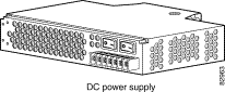
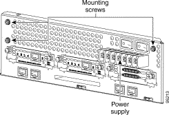
Figure 1 shows the universal DC power supply for Cisco 2691 routers.
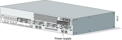
Figure 2 shows the location of the power supply in Cisco 2691 routers.
To access power supplies on the Cisco 2691 router, remove the router cover as described in the "Removing the Router Cover" section.
The power supply and cabling for the Cisco 2691 router is contained inside the chassis. To replace the power supply, complete these procedures:
To gain access to the Cisco 2691 power supply, you must first remove the chassis cover:
Step 2 Remove all network interface cables from the rear panel.
Step 3 If you have an AC-powered router, remove the power cord.
|
Note If you are upgrading from an AC power supply to a universal DC power supply, cover the existing stamped rating on the chassis with the label included with the universal DC power supply. |
Step 4 The following warnings apply to routers with DC power supplies:
If you have a DC-powered router, follow these steps to remove the power cables:
a. Lift and remove the terminal block cover.
b. Use a screwdriver to remove the three power leads from the terminal block, in this order: negative, positive, then ground.
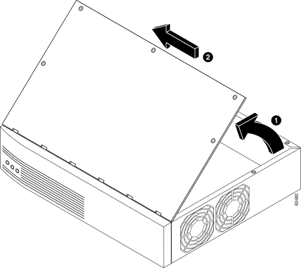
Step 5 Place the router so the rear panel is closest to you. Remove the five screws located on top of the cover. Set the screws aside in a safe place.
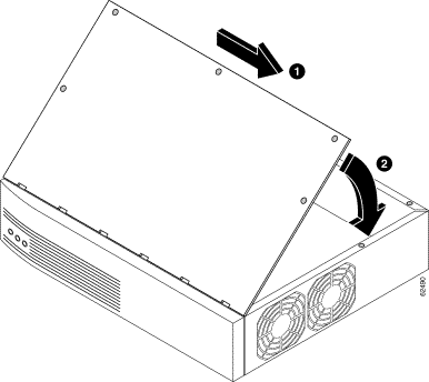
Step 6 Lift the front edge of the cover. (See number 1 in Figure 3.)
Step 7 Slide the cover toward the right until the metal tabs on the rear edge separate from the chassis bottom. (See number 2 in Figure 3.)
Step 8 Lift the cover completely off and set it aside.
When you are ready to replace the cover, see the "Replacing the Router Cover" section.
After you remove the cover from the chassis, follow this procedure to remove the power supply:
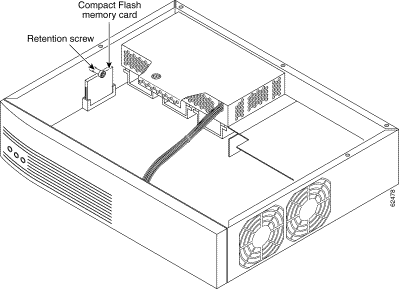
Step 2 Remove the Compact Flash memory retention screw and set it aside. (See Figure 4.)
Step 3 Lift the Compact Flash memory card up and away from the Compact Flash receptacle and set it aside. (See Figure 4.)
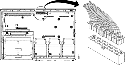
Step 4 Find the large power connector on the motherboard and remove it. (See Figure 5.)
|
Note On a Cisco 2691 router, you can simply lift the connector away from the receptacle. (See Figure 5.) |
Step 5 The Cisco 2691 power supply is held in the chassis by three external mounting screws at the rear of the router. (See Figure 6.) Remove the screws and set them aside.
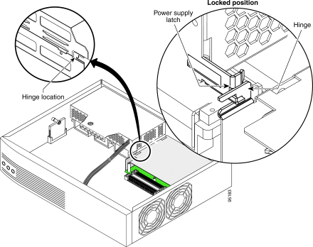
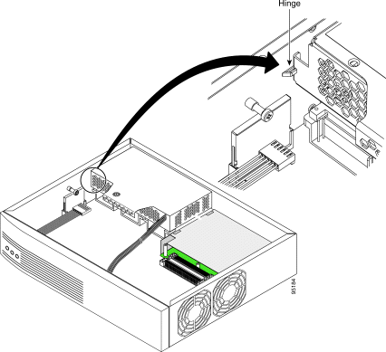
Step 6 Slide the power supply back slightly in the chassis. This disengages the hooks built into the chassis that help secure the power supply. (See Figure 7 and Figure 8.)
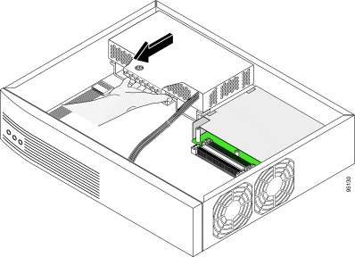
Step 7 Pull the power supply back and lift the power supply out of the chassis. (See Figure 9.)
To install a power supply in the chassis, follow these steps:
Step 2 Slide the power supply toward the rear of the chassis, engaging the hooks in the chassis.
Step 3 Replace the external rear mounting screws. (See Figure 6.)
Step 4 Insert the large power connector into the receptacle on the motherboard. (See Figure 5.)
Step 5 Reinsert the Compact Flash memory card in the receptacle and screw in the Compact Flash memory retention screw.
After you finish replacing the power supply, follow these steps to replace the cover:
Step 2 Hold the cover so the tabs at the rear of the cover are aligned with the chassis bottom.
Step 3 Push the cover toward the rear, making sure that the cover tabs fit under the chassis back panel, and the back panel tabs fit under the cover.
Step 4 Slide the cover slightly to the left to lock the cover into position (number 1 in Figure 10).
Step 5 Lower the front of the cover onto the chassis (number 2 in Figure 10).
Step 6 Fasten the cover with the five screws you set aside earlier.
Step 7 Reinstall the chassis on a rack.
Step 8 Reinstall network interface cables.
Step 9 Proceed to the "Connecting Cisco 2691 Routers to DC Power" section.
If your router has a DC-input power supply, follow the directions in this section for proper wiring.
|
Warning This unit is intended for installation in restricted access areas. A restricted access area can be accessed only through the use of a special tool, lock and key, or other means of security. To see translations of the warnings that appear in this publication, refer to the Regulatory Compliance and Safety Information document that accompanied this device. |
|
Caution If you connect parallel dual 48V DC power sources, both sources must be the same polarity. Do not connect -48V and +48V sources to a Cisco 2691 router. Opposite-polarity sources connected in parallel will damage the power supply. |
|
Note The installation must comply with the 2002 National Electric Code (NEC) and other applicable codes. |
|
Warning Read the installation instructions before connecting the system to the power source. To see translations of the warnings that appear in this publication, refer to the Regulatory Compliance and Safety Information document that accompanied this device. |
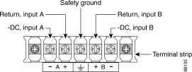
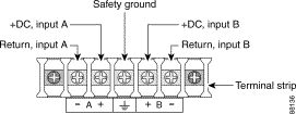
A Cisco 2691 router with a DC-input power supply requires copper wire and crimp-type ring terminals for the power connections. Table 1 summarizes the wiring requirements.
You can connect a single DC power source to either the A input or the B input. If there are dual power sources, connect one source to the A input and one source to the B input; both sources must be the same polarity and voltage.
Table 1 DC Wiring Requirements for Cisco 2691 Routers
|
|
1 The input voltage tolerance limits for nominal 24/48 V power supplies are 18 and 72 VDC. 2 The input voltage tolerance limits for nominal 48 V power supplies are 38 and 72 VDC. |
To connect the router to a DC power source, complete the following steps:
Step 2 Crimp the ring terminals to the DC power input wires.
|
Warning When stranded wiring is required, use approved wiring terminations, such as closed-loop or spade-type with upturned lugs. These terminations should be the appropriate size for the wires and should clamp both the insulation and conductor. To see translations of the warnings that appear in this publication, refer to the Regulatory Compliance and Safety Information document that accompanied this device. |
Step 3 Remove the plastic covers from the terminal block. Save them for reinstallation after you finish wiring.
|
Note Do not remove the colored screw at either end of the terminal block. Those are the terminal mounting screws. |
Step 4 Connect the DC power input wires to the terminal block as shown in Figure 11 or Figure 12. To avoid interference with the on/off switches, and to bring the wires close to the cable-tie attachment point, organize the wires downward from the terminal block.
|
Warning This warning applies only to units equipped with DC input power supplies. Wire the DC power supply using the appropriate lugs at the wiring end. The proper wiring sequence is ground to ground, positive to positive, and negative to negative. Note that the ground wire should always be connected first and disconnected last. To see translations of the warnings that appear in this publication, refer to the Regulatory Compliance and Safety Information document that accompanied this device. |
|
Caution Do not overtorque the terminal block contact screws. Recommended torque is 8.0 ± 0.5 in-lb (0.93 ± 0.05 N-m). |
|
Warning An exposed wire lead from a DC-input power source can conduct harmful levels of electricity. Be sure that no exposed portion of the DC-input power source wire extends from the terminal block plug. To see translations of the warnings that appear in this publication, refer to the Regulatory Compliance and Safety Information document that accompanied this device. |
|
Warning Blank faceplates and cover panels serve three important functions: they prevent exposure to hazardous voltages and currents inside the chassis; they contain electromagnetic interference (EMI) that might disrupt other equipment; and they direct the flow of cooling air through the chassis. Do not operate the system unless all cards, faceplates, front covers, and rear covers are in place. To see translations of the warnings that appear in this publication, refer to the Regulatory Compliance and Safety Information document that accompanied this device. |
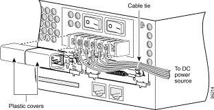
Step 2 Secure the wires using cable ties as shown in Figure 13. The chassis has a cable-tie attachment below and to the right of the terminal block.
|
Warning Do not disconnect connections to this equipment unless power has been removed or you have verified that the area is nonhazardous. Secure any external connections that mate to this equipment by using screws, sliding latches, threaded connectors, or other means provided with this product. To see translations of the warnings that appear in this publication, refer to the Regulatory Compliance and Safety Information document that accompanied this device. |
Step 3 Apply the included label over the power supply identification stamped in sheet metal near the DC wire terminals.
|
Caution Never operate the router unless the unit is completely closed, to ensure adequate cooling. |
To power on the router, complete the following steps:
Step 2 Power on the router. The LED labeled SYSTEM on the front panel should come on.
If you encounter problems when you power on the router, see the "Troubleshooting" section that follows.
Check the following items to help isolate problems with the power supply installation:
Cisco provides several ways to obtain documentation, technical assistance, and other technical resources. These sections explain how to obtain technical information from Cisco Systems.
You can access the most current Cisco documentation on the World Wide Web at this URL:
http://www.cisco.com/univercd/home/home.htm
You can access the Cisco website at this URL:
International Cisco websites can be accessed from this URL:
http://www.cisco.com/public/countries_languages.shtml
Cisco documentation and additional literature are available in a Cisco Documentation CD-ROM package, which may have shipped with your product. The Documentation CD-ROM is updated monthly and may be more current than printed documentation. The CD-ROM package is available as a single unit or through an annual subscription.
Registered Cisco.com users can order the Documentation CD-ROM (product number DOC-CONDOCCD=) through the online Subscription Store:
http://www.cisco.com/go/subscription
You can find instructions for ordering documentation at this URL:
http://www.cisco.com/univercd/cc/td/doc/es_inpck/pdi.htm
You can order Cisco documentation in these ways:
http://www.cisco.com/en/US/partner/ordering/index.shtml
http://www.cisco.com/go/subscription
You can submit comments electronically on Cisco.com. On the Cisco Documentation home page, click Feedback at the top of the page.
You can e-mail your comments to bug-doc@cisco.com.
You can submit your comments by mail by using the response card behind the front cover of your document or by writing to the following address:
Cisco Systems
Attn: Customer Document Ordering
170 West Tasman Drive
San Jose, CA 95134-9883
Cisco provides Cisco.com, which includes the Cisco Technical Assistance Center (TAC) Website, as a starting point for all technical assistance. Customers and partners can obtain online documentation, troubleshooting tips, and sample configurations from the Cisco TAC website. Cisco.com registered users have complete access to the technical support resources on the Cisco TAC website, including TAC tools and utilities.
Cisco.com offers a suite of interactive, networked services that let you access Cisco information, networking solutions, services, programs, and resources at any time, from anywhere in the world.
Cisco.com provides a broad range of features and services to help you with these tasks:
To obtain customized information and service, you can self-register on Cisco.com at this URL:
The Cisco TAC is available to all customers who need technical assistance with a Cisco product, technology, or solution. Two levels of support are available: the Cisco TAC website and the Cisco TAC Escalation Center. The avenue of support that you choose depends on the priority of the problem and the conditions stated in service contracts, when applicable.
We categorize Cisco TAC inquiries according to urgency:
You can use the Cisco TAC website to resolve P3 and P4 issues yourself, saving both cost and time. The site provides around-the-clock access to online tools, knowledge bases, and software. To access the Cisco TAC website, go to this URL:
All customers, partners, and resellers who have a valid Cisco service contract have complete access to the technical support resources on the Cisco TAC website. Some services on the Cisco TAC website require a Cisco.com login ID and password. If you have a valid service contract but do not have a login ID or password, go to this URL to register:
http://tools.cisco.com/RPF/register/register.do
If you are a Cisco.com registered user, and you cannot resolve your technical issues by using the Cisco TAC website, you can open a case online at this URL:
http://www.cisco.com/en/US/support/index.html
If you have Internet access, we recommend that you open P3 and P4 cases through the Cisco TAC website so that you can describe the situation in your own words and attach any necessary files.
The Cisco TAC Escalation Center addresses priority level 1 or priority level 2 issues. These classifications are assigned when severe network degradation significantly impacts business operations. When you contact the TAC Escalation Center with a P1 or P2 problem, a Cisco TAC engineer automatically opens a case.
To obtain a directory of toll-free Cisco TAC telephone numbers for your country, go to this URL:
http://www.cisco.com/warp/public/687/Directory/DirTAC.shtml
Before calling, please check with your network operations center to determine the level of Cisco support services to which your company is entitled: for example, SMARTnet, SMARTnet Onsite, or Network Supported Accounts (NSA). When you call the center, please have available your service agreement number and your product serial number.
Information about Cisco products, technologies, and network solutions is available from various online and printed sources.
http://www.cisco.com/en/US/products/products_catalog_links_launch.html
http://www.cisco.com/en/US/about/ac123/ac114/about_cisco_packet_magazine.html
http://business.cisco.com/prod/tree.taf%3fasset_id=44699&public_view=true&kbns=1.html
http://www.cisco.com/en/US/about/ac123/ac147/about_cisco_the_internet_protocol_journal.html
http://www.cisco.com/en/US/learning/le31/learning_recommended_training_list.html
This document is to be used in conjunction with Cisco 2600 Series Hardware Installation Guide and the Regulatory Compliance and Safety Information document for your router.
CCIP, CCSP, the Cisco Arrow logo, the Cisco Powered Network mark, Cisco Unity, Follow Me Browsing, FormShare, and StackWise are trademarks of Cisco Systems, Inc.; Changing the Way We Work, Live, Play, and Learn, and iQuick Study are service marks of Cisco Systems, Inc.; and Aironet, ASIST, BPX, Catalyst, CCDA, CCDP, CCIE, CCNA, CCNP, Cisco, the Cisco Certified Internetwork Expert logo, Cisco IOS, the Cisco IOS logo, Cisco Press, Cisco Systems, Cisco Systems Capital, the Cisco Systems logo, Empowering the Internet Generation, Enterprise/Solver, EtherChannel, EtherSwitch, Fast Step, GigaStack, Internet Quotient, IOS, IP/TV, iQ Expertise, the iQ logo, iQ Net Readiness Scorecard, LightStream, MGX, MICA, the Networkers logo, Networking Academy, Network Registrar, Packet, PIX, Post-Routing, Pre-Routing, RateMUX, Registrar, ScriptShare, SlideCast, SMARTnet, StrataView Plus, Stratm, SwitchProbe, TeleRouter, The Fastest Way to Increase Your Internet Quotient, TransPath, and VCO are registered trademarks of Cisco Systems, Inc. and/or its affiliates in the U.S. and certain other countries.
All other trademarks mentioned in this document or Web site are the property of their respective owners. The use of the word partner does not imply a partnership relationship between Cisco and any other company. (0304R)
Copyright © 2001-2003, Cisco Systems, Inc.
All rights reserved.
![]()
![]()
![]()
![]()
![]()
![]()
![]()
![]()
Posted: Thu Jul 31 14:57:52 PDT 2003
All contents are Copyright © 1992--2003 Cisco Systems, Inc. All rights reserved.
Important Notices and Privacy Statement.