|
|

Table Of Contents
Cisco Easy VPN Client for the Cisco 1700 Series Routers
Configuring the DHCP Server Pool (Required for Client Mode)
Verifying the DHCP Server Pool
Configuring and Assigning the Cisco Easy VPN Client Profile
Verifying the Cisco Easy VPN Configuration
Configuring the VPN 3000 Series Concentrator
Cisco 1700 Router Configured as a VPN Client
VPN Concentrator Configured as an IPsec Server
Simultaneous Client Server Functionality
Server 1 Configuration Example
Client 1 and Server 2 Configuration Example
Client 2 Configuration Example
Obtaining Technical Assistance
Cisco Easy VPN Client for the Cisco 1700 Series Routers
This document provides information on configuring and monitoring the Cisco Easy VPN client feature to support the Cisco 1700 series routers as IPSec clients of the VPN 3000 series concentrator. The following topics are included:
•
Simultaneous Client Server Functionality
•
Feature Overview
Routers and other broadband devices provide high-performance connections to the Internet, but many applications also require the security of virtual private network (VPN) connections that perform a high level of authentication and that encrypt the data between two particular endpoints. However, establishing a VPN connection between two routers can be complicated, and it typically requires tedious coordination between network administrators to configure the two routers' VPN parameters.
The Cisco Easy VPN Client feature eliminates much of this tedious work by implementing Cisco's Unity Client protocol, which allows most VPN parameters to be defined at a VPN 3000 series concentrator acting as an IPSec server.
The Cisco Easy VPN client feature can be configured in one of two modes: client mode or network extension mode. Client mode is the default configuration and allows only devices at the client site to access resources at the central site. Resources at the client site are unavailable to the central site. Network extension mode allows users at the central site (where the VPN 3000 series concentrator is located) to access network resources on the client site.
After the IPSec server has been configured, a VPN connection can be created with minimal configuration on an IPSec client, such as a supported Cisco 1700 series router. When the IPSec client initiates the VPN tunnel connection, the IPSec server pushes the IPSec policies to the IPSec client and creates the corresponding VPN tunnel connection.
Note
The following policies are pushed from the VPN concentrator to the Cisco Easy VPN client-enabled 1700 series router:
•
•
•
•
•
Refer to the document at the following URL to obtain instructions on configuring the DHCP server pool, and to see the Easy VPN client profile required for implementing Easy VPN. This document contains configuration examples for the Cisco 1700 router.
http://www.cisco.com/univercd/cc/td/doc/product/software/ios122/122newft/122t/122t13/ftezvpcm.htm
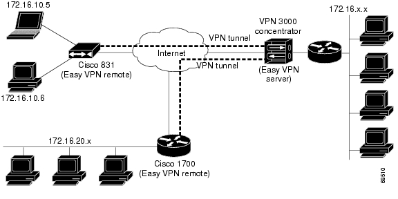
Figure 1 shows the network extension mode of operation. In this example, the Cisco 1700 series router and a Cisco 831 cable access router both act as Easy VPN clients, connecting to a VPN 3000 series concentrator. The PCs and hosts attached to the two routers have IP addresses that are in the same address range as that of the destination enterprise network; this results in a seamless extension of the remote network.
Figure 1 Network Extension Mode
Restrictions
The Cisco Easy VPN client feature supports configuration of only one destination peer. If your application requires creation of multiple VPN tunnels, you must manually configure the IPSec VPN and Network Address Translation/Peer Address Translation (NAT/PAT) parameters on both the client and the server.
Related Documents
This section lists other documentation related to the configuration and maintenance of the supported routers and the Cisco Easy VPN client feature.
Platform Documentation
The following documents provide information for specific Cisco routers:
•
•
•
•
•
•
•
IPsec and VPN Documentation
For general information about IPsec and VPNs, see the following information in the product literature and the IP technical tips sections on Cisco.com:
•
•
•
The following technical documents, available on Cisco.com and on the Documentation CD-ROM, also provide more in-depth configuration information:
•
Cisco IOS security features.•
•
Prerequisites
The following conditions must exist in order to use the Cisco Easy VPN client feature on the Cisco 1700 series routers:
•
•
Configuration Tasks
The following sections describe the tasks for configuring the Cisco Easy VPN client feature:
•
•
•
•
•
Configuring the DHCP Server Pool (Required for Client Mode)
The local router uses the DHCP protocol to assign IP addresses to the PCs or other hosts that are connected to the router's LAN interface. This requires creating a pool of IP addresses for the router's onboard DHCP server. The DHCP server then assigns an IP address from this pool to each PC or other host when it connects to the router.
In a typical VPN connection, the PCs or other hosts connected to the router's LAN interface are assigned an IP address in a private address space. The router then uses NAT/PAT to translate those IP addresses into a single IP address that is transmitted across the VPN tunnel connection.
To configure the DHCP server pool, follow these steps:
Verifying the DHCP Server Pool
To verify that the DHCP server pool has been correctly configured, use the following procedure.
Step 1
Router# show ip dhcp poolPool localpool :Current index : 192.168.100.1Address range : 192.168.100.1 - 192.168.100.254Router#Step 2
Router# show ip dhcp importAddress Pool Name: localpoolDomain Name Server(s): 192.168.20.5NetBIOS Name Server(s): 192.168.20.6Router#Step 3
Router# show ip dhcp bindingIP address Hardware address Lease expiration Type192.168.100.3 00c0.abcd.32de Nov 01 2001 12:00 AM Automatic192.168.100.5 00c0.abcd.331a Nov 01 2001 12:00 AM AutomaticRouter#Configuring and Assigning the Cisco Easy VPN Client Profile
The router acting as the IPSec client must create an Easy VPN profile and assign it to the outgoing interface. To configure and assign the profile, use the following procedure:
Verifying the Cisco Easy VPN Configuration
Follow these steps to verify that the Easy VPN profile has been correctly configured, that the profile has been assigned to an interface, and that the IPSec VPN tunnel has been established:
Step 1
R2#sh cry ip cl ezTunnel name :prof2Inside interface list:FastEthernet0/0,Serial0/1Outside interface:Serial0/0Current State:IPSEC_ACTIVELast Event:SOCKET_UPAddress:100.0.1.2Mask:255.255.255.255R2#Step 2
Router# show ip nat statisticsTotal active translations: 0 (0 static, 0 dynamic; 0 extended)Outside interfaces:cable-modem0Inside interfaces:Ethernet0Hits: 1489 Misses: 1Expired translations: 1Dynamic mappings:-- Inside Sourceaccess-list 198 pool enterprise refcount 0pool enterprise: netmask 255.255.255.0start 198.1.1.90 end 198.1.1.90type generic, total addresses 1, allocated 0 (0%), misses 0\Router#Step 3
Router# show access-listExtended IP access list 198permit ip 192.1.1.0 0.0.0.255 anyRouter#
Note
Step 4
Router# show crypto isakmp keyHostname/Address Preshared Key193.1.1.1 hw-client-passwordRouter#Configuring the VPN 3000 Series Concentrator
Use the following guidelines to configure the Cisco VPN 3000 series concentrator for use with Cisco Easy VPN clients.
Note
•
•
•
This proposal is active by default, but verify that it is still an active proposal using the
Configuration | System | Tunneling Protocols | IPSec | IKE Proposals screen.
Note
•
–
–
–
–
–
Release 3.5 of the Cisco VPN 3000 series concentrator is preconfigured with several default security associations, but they do not meet the IKE proposal requirements. To use an IKE proposal of CiscoVPNClient-3DES-MD5, copy the ESP/IKE-3DES-MD5 security association. Then modify it to use CiscoVPNClient-3DES-MD5 as its IKE proposal. This is configured on the VPN 3000 series concentrator using the Configuration | Policy Management | Traffic Management | Security Associations screen.
Configuration Examples
This section includes the followng configuration examples:
•
•
Cisco 1700 Router Configured as a VPN Client
The following example configures a Cisco 1700 series router as an IPSec client using the
Cisco Easy VPN feature in the client mode of operation. This example shows the following components of the Cisco Easy VPN Client configuration:•
•
Note
•
Current configuration :1308 bytes!version 12.2service timestamps debug uptimeservice timestamps log uptimeno service password-encryption!hostname 1760!aaa new-model!!aaa session-id common!ip subnet-zero!ip audit notify logip audit po max-events 100!crypto ipsec client ezvpn hw3connect autogroup ez key ezmode clientpeer 7.7.7.1crypto ipsec client ezvpn hw1connect manualgroup ezvpn key ezvpnmode clientpeer 6.6.6.1!interface FastEthernet0/0ip address 5.5.5.2 255.255.255.0speed autocrypto ipsec client ezvpn hw3 inside!interface Serial0/0ip address 4.4.4.2 255.255.255.0no ip route-cacheno ip mroute-cacheno fair-queuecrypto ipsec client ezvpn hw1 inside!interface Serial0/1ip address 3.3.3.2 255.255.255.0crypto ipsec client ezvpn hw1 inside!interface Serial1/0ip address 6.6.6.2 255.255.255.0clockrate 4000000crypto ipsec client ezvpn hw1!interface Serial1/1ip address 7.7.7.2 255.255.255.0no keepalivecrypto ipsec client ezvpn hw3!ip classlessno ip http serverip pim bidir-enable!radius-server retransmit 3radius-server authorization permit missing Service-Type!line con 0line aux 0line vty 0 4!no scheduler allocateend1760#sh crypto ipsec client ezvpnTunnel name :hw1Inside interface list:Serial0/0, Serial0/1,Outside interface:Serial1/0Current State:IPSEC_ACTIVELast Event:SOCKET_UPAddress:8.0.0.5Mask:255.255.255.255Default Domain:cisco.comTunnel name :hw3Inside interface list:FastEthernet0/0,Outside interface:Serial1/1Current State:IPSEC_ACTIVELast Event:SOCKET_UPAddress:9.0.0.5Mask:255.255.255.255Default Domain:cisco.comVPN Concentrator Configured as an IPsec Server
The following example shows a VPN concentrator configuration for a Cisco 7100 VPN concentrator.
7100-concentrator#sh running-configBuilding configuration...Current configuration :1131 bytes!version 12.2service timestamps debug uptimeservice timestamps log uptimeno service password-encryption!hostname 7100-concentrator!aaa new-model!aaa authentication login xauth localaaa session-id common!memory-size iomem 15mmi polling-interval 60no mmi auto-configureno mmi pvcmmi snmp-timeout 180ip subnet-zero!ip ssh time-out 120ip ssh authentication-retries 3!crypto isakmp policy 1authentication pre-sharegroup 2!crypto isakmp client configuration group ezvpnkey ezvpndomain cisco.compool dynpoolacl 101!crypto ipsec transform-set proposal1 esp-des esp-sha-hmac!crypto dynamic-map foo 10set transform-set proposal1!crypto map foo isakmp authorization list ezvpncrypto map foo client configuration address respondcrypto map foo 10 ipsec-isakmp dynamic foo!interface FastEthernet0/0no ip addressshutdownspeed auto!interface Serial0/0ip address 13.0.0.5 255.0.0.0no ip route-cacheno ip mroute-cachecrypto map foo!ip local pool dynpool 8.0.0.5ip classlessno ip http serverip pim bidir-enable!line con 0line aux 0line vty 0 4!end7100-concentrator#Simultaneous Client Server Functionality
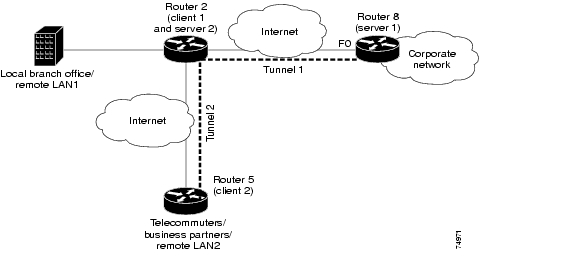
A Cisco 1700 series router can simultaneouslyact as a Easy VPN client and server.The following figure shows a typical scenario, where a local branch office provides a secure VPN tunnel to telecommuters at the same time that they provide another secure tunnel to corporate headquarters.
Figure 2 Simultaneous Client Server Functionality Scenario
Server 1 Configuration Example
The following example shows a configuration for server 1, represented in the figure by router 8.
R8#sh running-configBuilding configuration...Current configuration :1283 bytes!version 12.2service timestamps debug uptimeservice timestamps log uptimeno service password-encryption!hostname R8!aaa new-model!aaa authorization network hw-client-group localaaa session-id common!memory-size iomem 5ip subnet-zero!no ip domain-lookup!ip ssh time-out 120ip ssh authentication-retries 3!crypto isakmp policy 1authentication pre-sharegroup 2crypto isakmp client configuration address-pool local dynpool!crypto isakmp client configuration group hw-client-groupkey passworddns 172.168.0.250 172.168.0.251wins 172.168.0.252 172.168.0.253domain cisco.compool dynpool!crypto ipsec transform-set transform-1 esp-3des esp-md5-hmac!crypto dynamic-map dynmap 1set transform-set transform-1!crypto map dynmap isakmp authorization list hw-client-groupcrypto map dynmap client configuration address respondcrypto map dynmap 1 ipsec-isakmp dynamic dynmap!interface Ethernet0ip address 200.0.1.5 255.0.0.0half-duplex!interface FastEthernet0ip address 30.0.0.5 255.0.0.0speed autocrypto map dynmap!ip local pool dynpool 100.0.1.65 100.0.1.70ip classlessip route 0.0.0.0 0.0.0.0 30.0.0.51no ip http serverip pim bidir-enable!line con 0line aux 0line vty 0 4!no scheduler allocateendR8#Client 1 and Server 2 Configuration Example
The following example shows the configuration for the client 1 and server 2, represented in the figure by router 2.
R2#sh runR2#sh running-configBuilding configuration...Current configuration :2040 bytes!version 12.2service timestamps debug uptimeservice timestamps log uptimeno service password-encryption!hostname R2!aaa new-model!!aaa authorization network hw-server-group localaaa session-id common!memory-size iomem 5ip subnet-zero!no ip domain-lookup!ip ssh time-out 120ip ssh authentication-retries 3!crypto isakmp policy 1authentication pre-sharegroup 2crypto isakmp client configuration address-pool local dynpool!crypto isakmp client configuration group hw-server-groupkey passworddns 172.168.0.250 172.168.0.251wins 172.168.0.252 172.168.0.253domain cisco.compool dynpool!crypto ipsec transform-set transform-1 esp-3des esp-md5-hmac!crypto ipsec client ezvpn prof3connect autogroup hw-client-group key passwordmode clientpeer 30.0.0.5!crypto dynamic-map dynmap 1set transform-set transform-1!crypto map dynmap isakmp authorization list hw-server-groupcrypto map dynmap client configuration address respondcrypto map dynmap 1 ipsec-isakmp dynamic dynmap!interface FastEthernet0/0ip address 5.0.0.1 255.0.0.0speed autocrypto ipsec client ezvpn prof3 inside!interface Serial0/0ip address 1.0.0.1 255.0.0.0no fair-queuecrypto ipsec client ezvpn prof3!interface Serial0/1ip address 2.0.0.1 255.0.0.0crypto map dynmap <--- to provide server functionalitycrypto ipsec client ezvpn prof3 inside <-- to provide client functionality!! Note that the address range is in the same subnet as that of Serial 0/1! This is required if the users attached to client2 need to access corporate network behind server1! If the 2 tunnels need to be isolated then ip address pool has to be different from the subnet on the inside interface serial0/1ip local pool dynpool 2.0.0.3 2.0.0.100ip classless!line con 0line aux 0line vty 0 4!no scheduler allocateendR2#Client 2 Configuration Example
The following example shows a configuration for client 2, represented in the figure by router 5.
R5#sh running-configBuilding configuration...Current configuration :861 bytes!version 12.2service timestamps debug uptimeservice timestamps log uptimeno service password-encryption!hostname R5!ip subnet-zero!no ip domain-lookup!ip ssh time-out 120ip ssh authentication-retries 3!crypto ipsec client ezvpn prof3connect autogroup hw-server-group key passwordmode clientpeer 2.0.0.1!interface Loopback1ip address 10.0.0.1 255.0.0.0!interface FastEthernet0/0no ip addressshutdownspeed auto!interface Serial0/0ip address 3.0.0.1 255.0.0.0no fair-queuecrypto ipsec client ezvpn prof3 inside!interface Serial0/1ip address 2.0.0.2 255.0.0.0clock rate 2000000crypto ipsec client ezvpn prof3!ip default-gateway 2.0.0.1ip classlessip route 0.0.0.0 0.0.0.0 2.0.0.1no ip http serverip pim bidir-enable!line con 0line aux 0line vty 0 4!no scheduler allocateendR5#Obtaining Documentation
The following sections explain how to obtain documentation from Cisco Systems.
World Wide Web
You can access the most current Cisco documentation on the World Wide Web at the following URL:
Translated documentation is available at the following URL:
http://www.cisco.com/public/countries_languages.shtml
Documentation CD-ROM
Cisco documentation and additional literature are available in a Cisco Documentation CD-ROM package, which is shipped with your product. The Documentation CD-ROM is updated monthly and may be more current than printed documentation. The CD-ROM package is available as a single unit or through an annual subscription.
Ordering Documentation
Cisco documentation is available in the following ways:
•
http://www.cisco.com/cgi-bin/order/order_root.pl
•
http://www.cisco.com/go/subscription
•
Documentation Feedback
If you are reading Cisco product documentation on Cisco.com, you can submit technical comments electronically. Click Leave Feedback at the bottom of the Cisco Documentation home page. After you complete the form, print it out and fax it to Cisco at 408 527-0730.
You can e-mail your comments to bug-doc@cisco.com.
To submit your comments by mail, use the response card behind the front cover of your document, or write to the following address:
Cisco Systems
Attn: Document Resource Connection
170 West Tasman Drive
San Jose, CA 95134-9883We appreciate your comments.
Obtaining Technical Assistance
Cisco provides Cisco.com as a starting point for all technical assistance. Customers and partners can obtain documentation, troubleshooting tips, and sample configurations from online tools by using the Cisco Technical Assistance Center (TAC) Web Site. Cisco.com registered users have complete access to the technical support resources on the Cisco TAC Web Site.
Cisco.com
Cisco.com is the foundation of a suite of interactive, networked services that provides immediate, open access to Cisco information, networking solutions, services, programs, and resources at any time, from anywhere in the world.
Cisco.com is a highly integrated Internet application and a powerful, easy-to-use tool that provides a broad range of features and services to help you to
•
•
•
•
•
You can self-register on Cisco.com to obtain customized information and service. To access Cisco.com, go to the following URL:
Technical Assistance Center
The Cisco TAC is available to all customers who need technical assistance with a Cisco product, technology, or solution. Two types of support are available through the Cisco TAC: the Cisco TAC Web Site and the Cisco TAC Escalation Center.
Inquiries to Cisco TAC are categorized according to the urgency of the issue:
•
•
•
•
Which Cisco TAC resource you choose is based on the priority of the problem and the conditions of service contracts, when applicable.
Cisco TAC Web Site
The Cisco TAC Web Site allows you to resolve P3 and P4 issues yourself, saving both cost and time. The site provides around-the-clock access to online tools, knowledge bases, and software. To access the Cisco TAC Web Site, go to the following URL:
All customers, partners, and resellers who have a valid Cisco services contract have complete access to the technical support resources on the Cisco TAC Web Site. The Cisco TAC Web Site requires a Cisco.com login ID and password. If you have a valid service contract but do not have a login ID or password, go to the following URL to register:
http://www.cisco.com/register/
If you cannot resolve your technical issues by using the Cisco TAC Web Site, and you are a Cisco.com registered user, you can open a case online by using the TAC Case Open tool at the following URL:
http://www.cisco.com/tac/caseopen
If you have Internet access, it is recommended that you open P3 and P4 cases through the Cisco TAC Web Site.
Cisco TAC Escalation Center
The Cisco TAC Escalation Center addresses issues that are classified as priority level 1 or priority level 2; these classifications are assigned when severe network degradation significantly impacts business operations. When you contact the TAC Escalation Center with a P1 or P2 problem, a Cisco TAC engineer will automatically open a case.
To obtain a directory of toll-free Cisco TAC telephone numbers for your country, go to the following URL:
http://www.cisco.com/warp/public/687/Directory/DirTAC.shtml
Before calling, please check with your network operations center to determine the level of Cisco support services to which your company is entitled; for example, SMARTnet, SMARTnet Onsite, or Network Supported Accounts (NSA). In addition, please have available your service agreement number and your product serial number.
![]()
![]()
![]()
![]()
![]()
![]()
![]()
![]()
Posted: Wed Sep 19 13:22:46 PDT 2007
All contents are Copyright © 1992--2007 Cisco Systems, Inc. All rights reserved.
Important Notices and Privacy Statement.