|
|

Cisco Product Numbers MEM-3C16M= and MEM-3C8M=
This publication provides the procedures for installing the Cisco 3000 memory upgrade kit. MEM-----3C16M= provides replacement dynamic random access memory (DRAM) single in-line memory modules (SIMMs) (an additional 12 megabytes (MB) of memory in the Cisco 3000 models 3101, 3102, 3103, and 3202) and MEM-3C8M= provides an additional 4 MB in models 3104 and 3204. This publication contains the following sections:
 | Warning To ensure your safety, be sure the power is off and the power cord disconnected before opening the chassis. |
 | Caution To avoid damaging ESD-sensitive components, be sure you have discharged all static electricity from your body before opening the chassis. |
Before performing procedures described in this publication, review the following sections: "Safety Recommendations," "Safety with Electricity," and "Tools and Equipment Required."
Follow these guidelines to ensure general safety:
 | Warning Before working on equipment that is connected to power lines, remove jewelry (including rings, necklaces, and watches). Metal objects will heat up when connected to power and ground and can cause serious burns or can weld to the terminals. |
Follow these guidelines when working on equipment powered by electricity:
Electrostatic discharge (ESD) can damage equipment and impair electrical circuitry. ESD damage occurs when electronic printed circuit cards are improperly handled and can result in complete or intermittent failures.
Always follow ESD prevention procedures when removing and replacing cards. Ensure that the chassis is electrically connected to earth ground. Wear an ESD wrist strap, ensuring that it makes good skin contact. Connect the clip to an unpainted chassis frame surface to safely channel unwanted ESD voltages to ground. To properly guard against ESD damage and shocks, the wrist strap and cord must operate effectively.
If no wrist strap is available, ground yourself by touching the metal part of the chassis.
You need the following tools and equipment to upgrade your system's memory:
This section outlines the steps required to open the Cisco 3000 chassis. In the following discussion, it is assumed that you are looking at the chassis from the front. Use Figure 2 as a guide when removing the cover and power supply tray.
 | Caution To avoid damaging ESD-sensitive components, be sure you have discharged all the static electricity from your body before opening the chassis (as discussed in the section, "Preventing Electrostatic Discharge Damage"). |
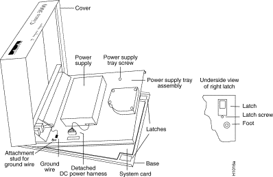
To remove the chassis cover, follow these steps:
Step 2 Remove all cables from the back of the chassis (including the power cable) to ensure that the unit is not powered on and that the cover will not get caught on the cables.
 | Caution Avoid damaging any cables as you remove the cover. |
Step 3 Turn the unit up so that the back of the chassis is resting on a surface, and the underside of the chassis is facing you, taking care not to damage the Ethernet or serial connectors.
Step 4 Remove the latch screw behind the latch on the right side of the underside of the chassis. The latch will not open until this screw is removed.
Step 5 Put the unit back down with the LEDs facing you.
Step 6 Place your fingers inside the two front latches on the underside of the chassis and push the latches away from you until they snap open.
Step 7 Lift the chassis cover from the front edge where the LEDs are located. The chassis cover will tilt up from the front toward the back. If you feel excessive resistance when opening the unit, one of the latches might still be closed. Push back on the latches again.
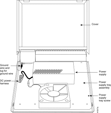
Step 8 Remove the ground wire (green with yellow stripes) connecting the left hinge post on the cover with the main ground stud, as shown in Figure 2. The ground wire is attached to the main ground stud with a FASTON lug, so the wire can be slipped off easily.
Step 9 Remove the chassis cover the rest of the way by pulling it up and forward so that the hinge posts come free from the notches in the bottom tray.
Step 10 Set the cover aside.
To access the Cisco 3000 system card, you must remove the power supply tray assembly as follows.
 | Caution If you lift the power supply tray assembly without first removing the power supply harness, you might damage the cable that provides all power to the system card. |
Step 2 Place your fingers underneath the front edge of the power supply tray assembly and pull the edge up. The latches holding the power supply tray assembly will release.
Step 3 Slide the power supply tray assembly toward you, lift it off the base, and remove it. The system card is now exposed. You do not need to remove the system card from the base of the chassis.
Step 4 Set the power supply tray assembly onto your work surface.
Step 5 Proceed to the section "Cisco 3000 Interface Options."
Table 4 lists the interface ports on the various Cisco 3000 models.
| Model | Ethernet | Token Ring | Serial | BRI |
|---|---|---|---|---|
2 | 0 | 0 | 0 | |
3102 (See Figure 5) | 1 | 0 | 1 | 0 |
3103 (See Figure 5) | 1 | 0 | 0 | 1 |
3202 (See Figure 6) | 0 | 1 | 1 | 0 |
3104 (See Figure 4) | 1 | 0 | 2 | 1 |
3204 (See Figure 3) | 0 | 1 | 2 | 1 |
| 1Figure 5 is indicative of the models 3101, 3102, and 3103. |
Figure 3 shows the location of the DRAM SIMM on the model 3204 system card.
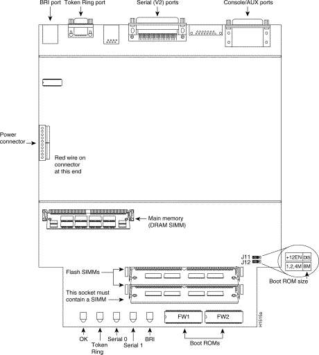
Figure 4 shows the location of the DRAM SIMM on the model 3104 system card.
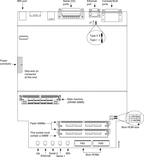
Figure 5 shows the location of the DRAM SIMMs on models 3101, 3102, and 3103. (Model 3101 is shown as typical of all three models.)
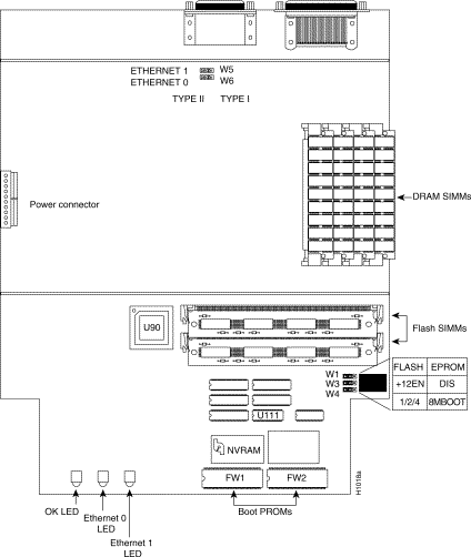
Figure 6 shows the location of the DRAM SIMMs on the model 3202 system card.
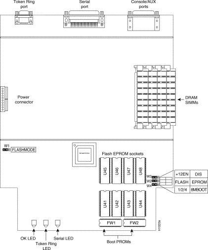
The router contains primary (main) and secondary (shared) memory. Primary and secondary memory size, in kilobytes (KB), is shown in the system banner on the console screen. Primary memory is implemented with dynamic random access memory (DRAM) single in-line memory modules (SIMMs). Secondary memory, used for packet buffering, consists of a fixed 512 KB (2 megabytes (MB) for models 3104 and 3204).
After booting up, the system banner displays the amount of system memory. The following example shows a system with 4096 KB (4 MB) of primary memory.
System Bootstrap, Version 4.6(0.15), SOFTWARE
Copyright (c) 1986-1992 by cisco Systems
Cisco 3000/030 processor with 4096 Kbytes of memory
>
Primary memory may need to be expanded when you use very large routing tables or many protocols. This might be necessary with configurations in which the router is set up as a connection device between large external networks and your internal network.
Memory upgrade kits for the router include four new 4 MB x 9 DRAM SIMMs.
Table 5 lists approved 4 MB x 9, 80-nanosecond DRAM SIMMs for models 3101, 3102, 3103, and 3202.
| Manufacturer's Name | Manufacturer's Part Number |
|---|---|
| Motorola | MCM94000AS80 |
| Micron | MT9D49M-8 |
| Texas Instruments | TM4100EAD9-80 |
After booting up, the system banner displays the amount of system memory.The following example shows a system with 4096 KB (4 MB) of primary memory and 512 KB (1/2 MB) of secondary memory:
System Bootstrap, Version 9.1 ROUTER SOFTWARE
Copyright (c) 1986-1992 cisco Systems, Inc.
Cisco 3000/030 processor with 4608 Kbytes of memory
>
The standard primary memory configuration of the router models 3104 and 3204 are 4 MB and 8 MB. You can upgrade from 4 MB of DRAM (main memory) by replacing the 72-pin DRAM SIMM in the main memory socket on the system card. Memory upgrade kits for router models 3104 and 3204 are obtainable from us. If you are upgrading with DRAM SIMMs you obtain from other vendors, use the SIMMs listed in Table 5.
| Manufacturer's Name | Manufacturer's Part Number |
|---|---|
| Micron | MT18D236M-8 |
| NEC | MC-422000A36B-80 |
You can upgrade your router, models 3204 and 3104, from the standard 4 MB of primary memory to 8 MB (see Table 5) using the memory upgrade kit as follows:
Step 2 Attach ESD protection.
Step 3 Open the cover according to the procedures in the section "Cover and Tray Removal Procedures."
Step 4 Locate the primary memory (DRAM SIMMs) by using Figure 3 or Figure 4.
Step 5 Remove the existing DRAM SIMMs by pulling outward on the connectors to unlatch them, as shown in Figure 7 . Be careful not to break the holders on the SIMM connector.
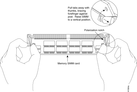
Step 6 Insert the new DRAM SIMM into the open connector by sliding the end with the metal fingers into the DRAM SIMM connector socket, at approximately a 45-degree angle to the system card. Gently rock the DRAM SIMM back into place until the latch on either side snaps into place. Do not use excessive force, or the connector could break.
Step 7 Reassemble the router following the procedures in the section "Replacing the Chassis Cover and Tray," taking care not to pinch the DC power harness.
Step 8 Connect the router to a console terminal and turn ON the power. If error messages relating to memory are displayed, repeat steps 1 through 6, taking care to firmly seat the SIMM in its socket.
You can upgrade your router, models 3101, 3102, 3103, and 3202 from the standard 4 MB of primary memory to 16 MB using the memory upgrade kit as follows:
Step 2 Attach ESD protection.
Step 3 Open the cover according to the procedures in the section "Cover and Tray Removal Procedures."
Step 4 Locate the DRAM SIMMs by using Figure 5 or Figure 6.
Step 5 Remove the existing DRAM SIMMs by pulling outward on the connectors to unlatch them, as shown in Figure 7 . Be careful not to break the holders on the SIMM connector.
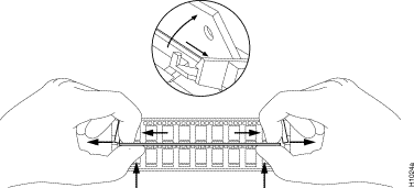
Step 6 Plug each new DRAM SIMM (4 MB x 9) into the open connector. To insert a new DRAM SIMM card, slide the end with the metal fingers straight down into the SIMM connector socket, at an angle perpendicular to the card. Gently rock the DRAM SIMM back toward the SIMMs already installed, and snap into place. Do not use excessive force, or the connector could break.
Step 7 Repeat step 5 for each new DRAM SIMM card.
Step 8 Reassemble the router following the procedures in the section "Replacing the Chassis Cover and Tray," taking care not to pinch the DC power harness.
Step 9 Connect the router to a console terminal and turn ON the power. If error messages relating to memory are displayed, repeat steps 1 through 7, taking care to firmly seat the DRAM SIMMs in their sockets.
After you have performed the memory upgrade for your system, replace the cover and component tray by following these steps:
Step 2 Replace the ground wire.
Step 3 Replace the DC power harness, taking care not to pinch the DC power harness.
Step 4 Replace the chassis cover.
Step 5 Replace the screw that holds the cover down.
Step 6 Replace the latch screw.
Step 7 Replace the chassis cables.
To test the SIMM upgrade installation, perform the following check:
Step 2 Turn on the power. If you get an error message relating to memory, repeat steps 1 through 8 of the section "Upgrading to 16 MB of Primary Memory in Models 3101, 3102, 3103, and 3202," taking care to firmly seat the SIMMs in their sockets.
This completes the Cisco 3000 memory upgrade procedures.


![]()
![]()
![]()
![]()
![]()
![]()
![]()
![]()
Posted: Thu Mar 14 06:38:20 PST 2002
All contents are Copyright © 1992--2002 Cisco Systems, Inc. All rights reserved.
Important Notices and Privacy Statement.