|
|

Cisco Product Numbers: MEM-3C4F=, MEM-1X4F=, MEM-1X8F=
This publication provides the procedures for installing the Cisco 3000 series memory upgrade kits: MEM-3C4F=, MEM-1X4F=, and MEM-1X8F= in Cisco 3000 Series models 3101, 3102, 3103, 3104, and 3204.
Certain IOS software releases require 8 MB of Flash memory to run from Flash. To upgrade to 4 MB of Flash memory, use the MEM-3C4F= Flash memory upgrade kit, which provides a single 4-MB Flash memory single in-line memory module (SIMM). To upgrade to 8 MB of Flash memory, use two 4-MB SIMMs (MEM-1X4F=) or one 8-MB SIMM (MEM-1X8F=).
This publication contains the following sections:
 | Warning To ensure your safety, be sure the power is off and the power cord disconnected before opening the chassis. |
 | Caution To avoid damaging electrostatic discharge (ESD) sensitive components, be sure you have discharged all static electricity from your body before opening the chassis. |
To successfully upgrade the Flash memory of your router, the following conditions must be met:
After installing the Flash memory upgrade, you will need to load a new system image into your router. Instructions for the system software upgrade are included in a separate publication. Before performing the procedures described in this publication, review the following sections: "Installation Prerequisites," "Tools and Equipment Required," "Safety Recommendations," and "Safety with Electricity."
You need the following tools and equipment to upgrade your system's memory:
Follow these guidelines to ensure general safety:
 | Warning Before working on equipment that is connected to power lines, remove jewelry (including rings, necklaces, and watches). Metal objects will heat up when connected to power and ground and can cause serious burns or can weld to the terminals. |
Follow these guidelines when working on equipment powered by electricity:
Electrostatic discharge (ESD) can damage equipment and impair electrical circuitry. ESD damage occurs when electronic printed circuit cards are improperly handled and can result in complete or intermittent failures.
Always follow ESD prevention procedures when removing and replacing cards. Ensure that the chassis is electrically connected to earth ground. Wear an ESD-preventive wrist strap, ensuring that it makes good skin contact. Connect the clip to an unpainted chassis frame surface to safely channel unwanted ESD voltages to ground. To properly guard against ESD damage and shocks, the wrist strap and cord must operate effectively.
If no wrist strap is available, ground yourself by touching the metal part of the chassis.
This section outlines the steps required to open the Cisco 3000 chassis. In the following discussion, it is assumed that you are looking at the chassis from the front. Use Figure 1 as a guide when removing the cover and power supply tray.
 | Caution To avoid damaging ESD-sensitive components, be sure you have discharged all the static electricity from your body before opening the chassis (as discussed in the section, "Preventing Electrostatic Discharge Damage"). |
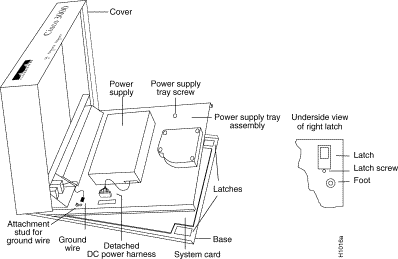
To remove the chassis cover, follow these steps:
Step 1 Turn OFF the unit and unplug it.
Step 2 Remove all cables from the back of the chassis (including the power cable) to ensure that the unit is not powered on and that the cover will not get caught on the cables.
 | Caution Avoid damaging any cables as you remove the cover. |
Step 3 Turn the unit up so that the back of the chassis is resting on a surface, and the underside of the chassis is facing you, taking care to avoid damaging the Ethernet or serial connectors.
Step 4 Remove the latch screw behind the latch on the right side of the underside of the chassis. The latch will not open until this screw is removed.
Step 5 Put the unit back down with the LEDs facing you.
Step 6 Place your fingers inside the two front latches on the underside of the chassis and push the latches away from you until they snap open.
Step 7 Lift the chassis cover from the front edge where the LEDs are located. The chassis cover will tilt up from the front, toward the back. If you feel excessive resistance when opening the unit, one of the latches might still be closed. Push back on the latches again.
Step 8 Remove the ground wire (green with yellow stripes) connecting the left hinge post on the cover with the main ground stud, as shown in Figure 2. The ground wire is attached to the main ground stud with a slip-on lug, so the wire can be slipped off easily.
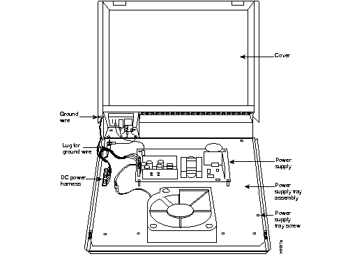
Step 9 Remove the chassis cover the rest of the way by pulling it up and forward so that the hinge posts come free from the notches in the bottom tray.
Step 10 Set the cover aside.
To access the Cisco 3000 system card, you must remove the power supply tray assembly as follows.
Step 1 Locate the DC power harness on the far left edge of the power supply tray assembly. (See Figure 2.) Detach the DC power harness from the system card under the power supply tray assembly using the pull tab on the DC power harness.
 | Caution If you lift the power supply tray assembly without first removing the power supply harness, you might damage the cable that provides all power to the system card. |
Step 2 Remove the power supply tray screw. (See Figure 2.)
Step 3 Place your fingers underneath the front edge of the power supply tray assembly and pull the edge up. The latches holding the power supply tray assembly will release.
Step 4 Slide the power supply tray assembly toward you, lift it off the base, and remove it. The system card is now exposed. You do not need to remove the system card from the base of the chassis.
Step 5 Set the power supply tray assembly onto your work surface.
Step 6 Proceed to the section "Locating the Flash Memory SIMMs."
To identify which model of Cisco 3000 you have, based on the network interfaces, use Table 4.
| Model | Ethernet | Token Ring | Serial | BRI |
|---|---|---|---|---|
| 3101 (see Figure 4)1 | 2 | 0 | 0 | 0 |
| 3102 (see Figure 4) | 1 | 0 | 1 | 0 |
| 3103 (see Figure 4) | 1 | 0 | 0 | 1 |
| 3104 (see Figure 3)2 | 1 | 0 | 2 | 1 |
| 3202 (not shown) | 0 | 1 | 1 | 0 |
| 3204 (see Figure 3) | 0 | 1 | 2 | 1 |
Refer to the appropriate figure to determine the location of Flash memory SIMMs on your system.
Figure 3 shows the location of the Flash SIMMs on models 3104 and 3204 system card. The socket closest to the boot ROMs must contain a SIMM when a single Flash memory SIMM is used.
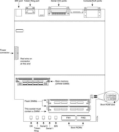
Figure 4 shows the location of the Flash SIMMs on models 3101, 3102, and 3103. The socket closest to the boot ROMs must contain a SIMM when a single Flash memory SIMM is used.
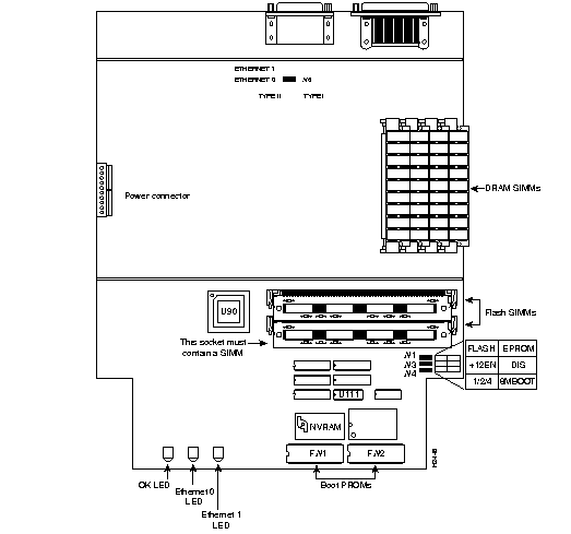
The router stores the system software image in Flash memory. Upgrading your Flash memory to 4 MB requires replacing the existing Flash memory SIMMs with one 4-MB Flash SIMM. Upgrading your Flash memory to 8 MB requires replacing the existing Flash memory SIMMs with two 4-MB Flash SIMMs or one 8-MB SIMM. The 80-pin 4-MB Flash memory SIMMs can be purchased from Cisco Systems or from the vendor listed in Table 5.
If you are replacing Flash memory with SIMMs you purchase from other vendors, be sure to use 4-MB, 120-nanosecond memory Flash SIMMs from the vendor listed in Table 5.
| Manufacturer's Name | Manufacturer's Part Number |
|---|---|
| SMART Modular Technologies | SM732C1000B-12 |
Follow these steps to upgrade the Flash memory on all Cisco 3000 series models except the model 3202, which employs Flash EPROMs:
Step 1 Turn OFF the router and unplug it.
Step 2 Open the chassis cover according to the procedures in the sections "Removing the Chassis Cover" and "Removing the Power Supply Tray Assembly."
Step 3 Locate the Flash memory SIMMs on the system card, as shown in Figure 3 and Figure 4. Your system may currently have one or two Flash memory SIMMs installed.
Step 4 Gently spread the Flash memory SIMM connector hold-downs until they are wide enough to permit you to remove the Flash memory SIMM. (See Figure 5.)
Step 5 Repeat these steps for all the Flash memory SIMMs to be replaced.
 | Caution Do not push on the Flash chips themselves. Handle the Flash SIMM and its components with care, because they are fragile and can break. |
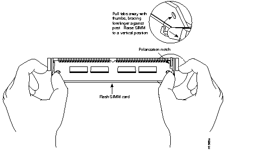
Step 6 Plug the new Flash memory SIMM into the open connector. To insert a new SIMM, slide the end with the metal fingers straight down into the SIMM connector socket, at an angle perpendicular to the system card. Gently rock the SIMM back toward the SIMMs already installed and snap into place. Do not use excessive force, because the connector could break.
To replace the boot PROM software with a new software image, the existing boot PROMs must be replaced. Table 6 lists the part numbers you need and indicates their installation socket. The part number is printed on a label attached to the boot PROM.
| Boot PROM Part Number | Installation Socket |
|---|---|
| 17-1610-03 | FW1 |
| 17-1611-03 | FW2 |
The following tools and equipment are required to replace the boot PROMs:
Follow this procedure to replace the boot ROMs:
Step 1 To open the chassis and expose the boot PROMs, follow the procedures in the section "Cover and Tray Removal Procedures" on page 4 through page 6.
Step 2 After the boot PROMs (FW1 and FW2) on the system card are exposed, perform steps 3 through 6 to replace the PROMs.
Step 3 Locate the boot PROMs, FW1 and FW2 (see Figure 3 or Figure 4).
Step 4 Using an EPROM extraction tool or a small flat-blade screwdriver, gently remove the boot PROMs and set them aside (on a nonconductive surface).
Step 5 Insert the new boot PROMs in their respective sockets in the orientation show in Figure 3 or Figure 4, being careful not to bend or crush any of the bottom pins. If you inadvertently bend a pin, use needle nose pliers to straighten them. Align the notch in the new PROM with the notch in the PROM socket, ignoring the orientation of the label.
Step 6 Replace the tray assembly and cover following the instructions in the next section.
After performing the memory upgrade for your system, while referring to Figure 2, replace the cover and component tray by following these steps:
Step 1 Replace the metal power supply tray on the chassis.
Step 2 Replace the power supply tray screw.
Step 3 Replace the ground wire.
Step 4 Replace the DC power harness, taking care not to pinch the DC power harness.
Step 5 Replace the chassis cover.
Step 6 Replace the screw that holds the cover down.
Step 7 Replace the latch screw.
Step 8 Replace the chassis cables.
This completes the Cisco 3000 Series Flash memory upgrade procedures.

|
|