|
|

Before you install the AccessPro card, read this chapter carefully. It contains important information that will make your installation quicker and easier. This chapter contains the following information:
Follow these guidelines to ensure general safety:
 | Warning Before working on equipment that is connected to power lines, remove jewelry (including rings, necklaces, and watches). Metal objects will heat up when connected to power and ground and can cause serious burns or weld the metal object to the terminals. |
Electrostatic discharge (ESD) can damage equipment and impair electrical circuitry. It occurs when electronic components are improperly handled and can result in complete or intermittent failures. Always follow ESD-prevention procedures when removing and replacing components. Ensure that the chassis is electrically connected to earth ground. Wear an ESD-preventive wrist strap, ensuring that it makes good skin contact. Connect the clip to an unpainted surface of the chassis frame to safely channel unwanted ESD voltages to ground. To properly guard against ESD damage and shocks, the wrist strap and cord must operate effectively. If no wrist strap is available, ground yourself by touching the metal part of the chassis.
 | Caution For safety, periodically check the resistance value of the antistatic strap, which should be between 1 and 10 megohms (Mohms). |
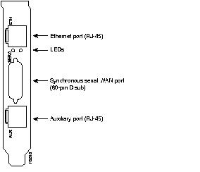
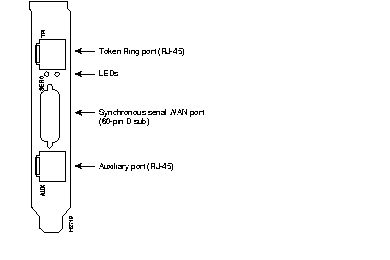
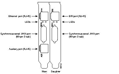
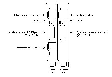
The ports for the Ethernet or Token Ring, serial, and auxiliary connections are located on the rear panel of the main card and the daughter card. (See Figure 2-1, Figure 2-2, Figure 2-3, and Figure 2-4.)


When you set up the LAN and WAN connections, be aware of the distance limitations and potential electromagnetic interference (EMI) as defined by the EIA. Following are the distance limitation specifications for Ethernet 10BaseT, Token Ring RJ-45, BRI, and serial interfaces.
The distance limitation for the IEEE 802.3 specification is a maximum segment distance of 1,640 feet (500 meters) at a transmission rate of 10 megabits per second (Mbps).
The distance limitation for the IEEE 802.5 specification is a maximum segment distance of 1,640 feet (500 meters) at a transmission rate of 4 or 16 Mbps.
The specifications for the BRI cable are given in Table 2-1.
| Specification | High-Capacitance Cable | Low-Capacitance Cable |
|---|---|---|
| Resistance (@ 96 kHz1) | 160 ohms/km | 160 ohms/km |
| Capacitance (@ 1 kHz) | 120 nF2/km | 30 nF/km |
| Impedance (@ 96 kHz) | 75 ohms | 150 ohms |
| Wire diameter | 0.024" (0.6 mm) | 0.024" (0.6 mm) |
| Distance limitation | 32.8' (10 m) | 32.8' (10 m) |
As with all signaling systems, EIA/TIA-232 signals can travel a limited distance at any given bit rate; generally, the slower the data rate, the greater the distance. Table 2-2 shows the standard relationship between baud rate and maximum distance for EIA/TIA-232 signals.
| Data Rate (Baud) | Distance (Feet) | Distance (Meters) |
|---|---|---|
| 2,400 | 200 | 60 |
| 4,800 | 100 | 30 |
| 9,600 | 50 | 15 |
| 19,200 | 25 | 7.6 |
| 38,400 | 12 | 3.7 |
 | Caution If you understand the electrical problems that can arise from violating the distance and speed limitations for EIA/TIA-232, and you can compensate for them, you might be able to get good results at distances greater than those shown in Table 2-2; however, we recommend that you stay within the distances defined by the standard. |
Balanced drivers allow EIA/TIA-449 signals to travel greater distances than EIA/TIA-232 signals. Table 2-3 lists the standard relationship between baud rate and maximum distance for EIA/TIA-449 signals. These limits are also valid for V.35 and X.21.
| Baud Rate | Distance (Feet) | Distance (Meters) |
|---|---|---|
| 2,400 | 4,100 | 1,250 |
| 4,800 | 2,050 | 625 |
| 9,600 | 1,025 | 312 |
| 19,200 | 513 | 156 |
| 38,400 | 256 | 78 |
| 56,000 | 102 | 31 |
| T1, E1 | 50 | 15 |
 | Caution The EIA/TIA-449 and V.35 interfaces support data rates up to 2.048 Mbps. Because data may be lost, exceeding this maximum is not recommended. |
When you run cables for any significant distance in an electromagnetic field, interference can occur between the field and the signals on the cables. This has two implications for the construction of terminal plant cabling:
If you use twisted-pair cables with a good distribution of grounding conductors in your plant cabling, emitted radio interference is unlikely. Although it is not recommended, if you exceed the maximum distances the best results will be received if you ground the conductor for each data signal.
If you have cables that exceed the recommended distances, or if you have cables that pass between buildings, give special consideration to the effect of lightning strikes or ground loops. The electromagnetic pulse caused by lightning or other high-energy phenomena can easily generate enough energy into unshielded conductors to destroy electronic devices. If your site has experienced this kind of problem, consult experts in lightning suppression and shielding.
Most data centers cannot resolve the infrequent but potentially catastrophic problems just described without pulse meters and other special equipment. Take precautions to avoid these problems by providing a properly grounded and shielded environment, and pay special attention to issues of electrical surge suppression.
To predict and remedy strong EMI, consult experts in radio frequency interference (RFI).
Access to the console port interface is available through the ISA bus using terminal emulation software running on the PC. To configure the card for console port functionality, refer to the section "Setting COMport Jumpers" in the chapter "Maintaining Your AccessPro Card."
An RJ-45, asynchronous serial, auxiliary port is included on all AccessPro cards. This is a DTE port to which you can attach a CSU/DSU or protocol analyzer for network access. This port connects to external equipment using an RJ-45-to-DB-25 adapter. (See Figure 2-5.) The appendix "Cabling Specifications" lists the pinouts for the auxiliary port.

This section contains information about connecting the Ethernet, Token Ring, serial, and BRI ports to your network.
The Ethernet 10BaseT interface port is located on the rear panel of the AccessPro card and is labeled ETH. Use a modular, RJ-45, UTP cable to connect the Ethernet port directly to a transceiver or Ethernet 10BaseT hub.
The Token Ring interface port is located on the rear panel of the AccessPro card and is labeled TR. Use a modular, RJ-45, UTP cable to connect the Token Ring port to a media attachment unit (MAU).
The serial interface port is located on the rear panel of the AccessPro card and is labeled SER. The serial port is a 60-pin, D-type connector. All serial interfaces except the EIA-530 interface can be configured as data communications equipment (DCE) using a DCE cable. The DTE serial port needs external clocking, which is provided by a CSU/DSU or modem.
You must use a special serial cable to connect the AccessPro card to a modem or CSU/DSU. This cable is available from us and is usually ordered with the system. The cable uses a DB-60 connector on the chassis end. For cable specifications, see the appendix "Cabling Specifications." For ordering information, contact a customer service representative.
On models with the BRI port (Model AP-EBC and Model AP-RBC), the BRI port is an RJ-45 8-pin connector located above the serial port on the daughter card. Use an appropriate cable to connect the system directly to the ISDN through the NT1. The common carrier will provide the NT1 connection worldwide, except in North America, where the NT1 is owned by individual customers.
|
|