|
|

This chapter explains how to maintain your AccessPro card and contains the following information:
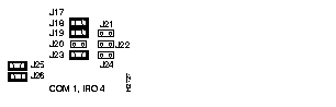
Because there is no external physical connector for the console port, you must direct the console port to a COMport on the PC. You do this by setting the COMport with jumpers J18 and J19 and then setting the IRQ using jumpers J20 and J23.
If you have additional cards or built-in interfaces on your PC motherboard that use internal COMports, the settings on your AccessPro card may need to be modified. Table 4-1 lists the jumper settings required to configure the PC COMport.
| Port Selection | J18 | J19 | IRQ Level | J20 | J23 |
|---|---|---|---|---|---|
| COM 1 | In | In | IRQ 4 | Out | In |
| COM 2 | Out | In | IRQ 3 (default) | In | Out |
| COM 3 | In | Out | IRQ 4 | Out | In |
| COM 4 (default) | Out | Out | IRQ 3 | In | Out |
| IRQ selection disabled | Disabled | Out | Out |
Although the PC has four COMports, only two can be active at the same time. COMports 1 and 3 share IRQ 4 and COMports 2 and 4 share IRQ 3. The PC will malfunction if two COMports using the same IRQ are used simultaneously. The AccessPro card has been configured to use COM 2 and IRQ 3. Table 4-2 lists the COMports, their I/O addresses, and IRQ settings.
| COMport | I/O Address | IRQ |
|---|---|---|
| 1 | $3F8 to $3FF | 4 |
| 2 | $2F8 to $2FF | 3 |
| 3 | $3E8 to $3EF | 4 |
| 4 | $2E8 to $2EF | 3 |
Change the settings on your AccessPro card if you are installing it in a system in which you have previously installed a card that is using COM 4 and IRQ 3. In this case, you would set your AccessPro card to use COM 1 and IRQ 4. You would also need to use a PC bus mouse so that the mouse does not require one of the available IRQs.
Figure 4-1 illustrates the appropriate jumper settings for the card using COMport 1.
The system code (software) is stored in Flash memory or programmable read-only memory (PROM) SIMMs. The 80-pin Flash memory and PROM SIMMs are provided in an ESD-protective bag within the shipping container. These SIMMs must be installed before you install your AccessPro card in the PC chassis.
Updates for your system code will be available for download from a TFTP server or with a system-code SIMM replacement.
The following tools are required to change the system-code SIMMs in your AccessPro card:
Following is the procedure for upgrading the system-code Flash memory:
Step 1 Turn OFF power but, to channel ESD voltages to ground, do not unplug the power cord.
Step 2 Remove the PC chassis cover, if it has not already been removed, following the instructions in your PC system manual.
Step 3 Attach an ESD-preventive wrist strap.
Step 4 Locate the AccessPro card in its ISA-bus slot if it has already been installed. Remove the screw that secures the card bracket to the PC chassis. If a daughter card is installed remove the screw that secures the daughter card bracket to the PC chassis.
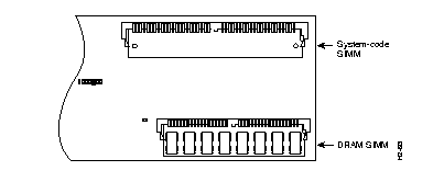
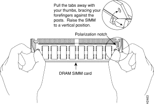
Step 5 Turn the card so it is oriented in the position shown in Figure 4-2, with the DRAM SIMMs toward you.
Step 6 Locate the system-code SIMMs on the system card (see Figure 4-3).
Step 7 Remove the existing system-code SIMMs (if any) by pulling outward on the connectors to unlatch them. The connector holds the SIMMs tightly, so be careful not to break the holders on the SIMM connector. (See Figure 4-4.)
 | Caution To prevent damage, do not push on the center of SIMMs. Handle each SIMM with care. |
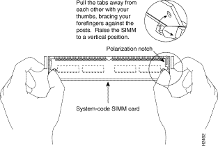
Step 8 Orienting the AccessPro card as shown in Figure 4-2, position the new SIMM so that the polarization notch is located at the right end of the SIMM socket.
Step 9 Insert the new SIMM by sliding the end with the metal fingers into the SIMM connector socket at approximately a 45-degree angle to the AccessPro card. Gently rock the SIMM back into place until the latch on either side snaps into place. Do not use excessive force, or the connector could break.
Step 10 Insert the AccessPro card into its ISA slot on the PC motherboard. Carefully align the edge connector on the ISA slot, and use a rocking motion to seat the card in the proper position. Secure the card in the ISA slot with the bracket screw.
Step 11 Replace the cover of the PC following the directions provided by the manufacturer and turn on the power.
Depending on the level of system features you have chosen for your card (IP only, Desktop, or Enterprise), the AccessPro card may be shipped with additional primary-memory DRAM SIMMs. The DRAM SIMMs are in an ESD-protective bag within the shipping container.
Table 4-3 lists approved 70-nanosecond (ns) DRAM SIMMs for the AccessPro card.
| 4-MB Upgrade (1 MB x 36, 70-ns DRAM SIMMs) | 16-MB Upgrade (4 MB x 36, 70-ns DRAM SIMMs) | ||
|---|---|---|---|
| Manufacturer | Part Number | Manufacturer | Part Number |
| Micron | MT9D136M-7 | Mitsubishi | MH4M36ANXJ-7 |
| NEC | MC421000A36BE-70 | - | - |
After booting up, your system will indicate in the system banner the amount of primary memory it has. The following example shows a system with 2 MB (2048 KB) of primary memory. (The system does not display shared memory.)
System Bootstrap, Version (2.1), SOFTWARE
Copyright (c) 1986-1994 by cisco Systems
2500 processor with 2048 Kbytes of main memory
>
If you use very large routing tables or many protocols, you might need to expand primary memory. This expansion might be necessary with configurations in which the AccessPro card is set up as a connection device between large external networks and your internal network.
The feature set you have chosen with your AccessPro card may require more than the standard 2 MB of DRAM. The memory requirements for the feature sets are listed in Table 4-4.
| Feature Set | Small Networks | Large Networks |
|---|---|---|
| IP only | 2 MB | 2 to 18 MB |
| IP with IBM Protocols | 2 MB | 2 to 18 MB |
| IP/IPX only | 2 MB | 2 to 18 MB |
| IP/IPX with IBM Protocols | 2 MB | 2 to 18 MB |
| Desktop | 4 MB | 6 to 18 MB |
| Desktop with IBM Protocols | 4 MB | 2 to 18 MB |
| Enterprise | 6 MB | 6 to 18 MB |
| Enterprise | 6 MB | 6 to 18 MB |
The following tools and equipment are required to install DRAM SIMMs in your AccessPro card:
Following is the procedure for installing DRAM SIMMs:
Step 1 Turn OFF the system power, but do not disconnect the power cord.
Step 2 Remove the PC chassis cover following the instructions in your PC system manual.
Step 3 Attach an ESD-preventive wrist strap to a ground point to prevent equipment damage.
Step 4 Locate the AccessPro card in its ISA-bus slot. Remove the screw that secures the card bracket to the PC chassis.
Step 5 Turn the card so it is oriented in the position shown in Figure 4-2, with the DRAM SIMMs toward you.
Step 6 Locate the DRAM SIMM socket on the AccessPro card
(see Figure 4-3).
Step 7 Remove the existing DRAM SIMMs (if any) by pulling outward on the connectors to unlatch them. The connector holds the SIMMs tightly; take care not to break the holders on the SIMM connector (Figure 4-5).
Step 8 Using the orientation shown in Figure 4-3, position the SIMM so that the polarization notch is located at the right end of the SIMM socket (see Figure 4-5).
| Caution To prevent damage, do not push on the center of the SIMMs. Handle each SIMM with care. |
Step 9 Insert the new DRAM SIMM by sliding the end with the metal fingers into the SIMM connector socket at approximately a 45-degree angle to the AccessPro card. Gently rock the SIMM until the latch on either side snaps into place. Do not use excessive force, or the connector could break.
Step 10 Insert the AccessPro card into its ISA slot on the PC motherboard. Carefully align the edge connector on the ISA slot, and use a rocking motion to seat the card in the proper position. Secure the card in the ISA slot with the bracket screw.
Step 11 Replace the cover of the PC following the directions provided by the manufacturer and turn on the power.
If you lose your password, or can't remember it, you can recover it.
Step 1 Using the terminal emulation program on your PC, either in Windows or DOS, connect to the console port.
Step 2 Configure the terminal to operate at 9600 baud, 8 data bits, no parity, 1 stop bit, and no flow control (or to whatever settings the AccessPro card is set).
Step 3 Enter the show version command to display the existing configuration register value. Note this value for later use in step 14.
Step 4 If Break is disabled, reboot the PC. If Break is enabled on the AccessPro card, send a Break and then proceed to step 5.
Step 5 Within 60 seconds of rebooting the PC, press the Break key. This causes the terminal to display the bootstrap program prompt (>).
Step 6 To reset the configuration register to boot from Flash memory and ignore NVRAM, enter the following command at the bootstrap prompt:
o/r
Step 7 Initialize the AccessPro card by entering the following command:
i
Step 8 The AccessPro card will power cycle, the configuration register will be set to 0x141, and the AccessPro card will boot the boot ROM system image and prompt you with the system configuration dialog as follows:
Enter no in response to the system configuration dialog prompts until the following system message is displayed:
Step 9 Press Return. The boot ROM prompt appears as follows:
Step 10 Enter the enable command to enter EXEC mode in the boot ROM image. The prompt changes to a pound sign (#):
Step 11 Enter the show configuration EXEC command to display the enable password in the configuration file and to display any boot system commands.
Step 12 Enter the configure terminal command at the EXEC prompt. You are prompted as follows:
conf term
Step 13 Enter no in response to any boot system command in the configuration file.
Step 14 Using the config-register 0xvalue command (using the value 0x102), change the configuration register value back to its original value (noted from step 3) or change it to a value of 0x2102 (the factory default).
Step 15 Exit configuration mode by pressing Ctrl-Z.
Step 16 Reboot the AccessPro card, then use the recovered password to enable the card.
Your AccessPro card was intensively tested before it was shipped from the factory. Although it is unlikely that the card will exhibit any problems, if your system appears to have problems starting up, read the remainder of this chapter to try and identify the problem.
To solve problems in the AccessPro card, you need to isolate the problem to a specific source, if possible. By comparing what the AccessPro is actually doing to what it should be doing, you can greatly simplify troubleshooting.
When troubleshooting the AccessPro card, consider the subsystems of the card:
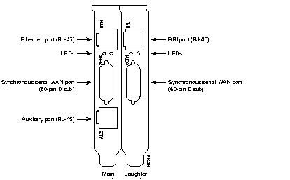
The AccessPro card and the daughter card each have two LED indicators on the rear panel. The LED on the left (when viewed from the rear of the PC) of the main card indicates the activity of the LAN interface on the card. The LED on the right side of the main card indicates its functional condition.
The LED on the left side of the daughter card indicates the activity on serial 1 port on the daughter card. The LED on the right side of the daughter card indicates the activity of the WAN (BRI) port. (see Figure 4-6.)
If the interface LED is not on when the interface is active and the interface is correctly connected, a problem might be indicated. Contact your system administrator. If an interface is extremely busy, its LED will be on all the time. The green OK LED will be on after the AccessPro card initializes correctly.
The cables that connect the AccessPro card to your network must be securely fastened to provide a trouble-free connection. If you suspect a problem with the cables, check the following conditions and contact your system administrator.
|
|