|
|

Table Of Contents
Multiplex Section-Shared Protection Rings
Subnetwork Connection Protection
SDH Topologies
This chapter explains CiscoONS15600SDH topologies. To provision topologies, refer to the CiscoONS15600SDH Procedure Guide.
Chapter topics include:
•
Multiplex Section-Shared Protection Rings
•
The ONS15600SDH usually operates as a hub node in networks that include ONS15454SDH nodes. Single nodes are installed at geographic locations where several ONS15454 SDH topologies converge. A single ONS15600SDH node might be a part of several ONS15454 SDH rings/networks.
To avoid errors during network configuration, Cisco recommends that you draw the complete ONS15600SDH topology on paper (or electronically) before you begin the physical implementation. A sketch ensures that you have adequate slots, cards, and fibers to complete the topology.
7.1 Linear ADM Configurations
You can configure ONS15600SDH nodes as a line of add/drop multiplexers (ADMs) by configuring one STM-N port as the working path and a second port as the protect path. Unlike rings, point-to-point (two node configurations) and linear (three node configurations) ADMs require that the STM-N ports at each node are in 1+1 Linear Multiplex Section Protection (LMSP) to ensure that a break to the working path automatically routes traffic to the protect path.
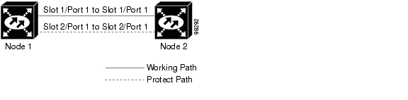
Figure7-1 shows two ONS15600SDH nodes in a point-to-point ADM configuration. Working traffic flows from Slot 1/Port 1 at Node 1 to Slot 1/Port 1 at Node 2. You create the protect path by creating a 1+1 LMSP configuration with Slot 1/Port 1 and Slot 2/Port 1 at Nodes 1 and 2.
Figure 7-1 Point-to-Point ADM Configuration
7.2 Multiplex Section-Shared Protection Rings
The ONS15600SDH can support 16 concurrent two-fiber multiplex section-shared protection rings (MS-SPRings). Each MS-SPRing can support up to 24 ONS15600SDH nodes. Because the working and protect bandwidths must be equal, you can create only STM-16 or STM-64 MS-SPRings.
Note
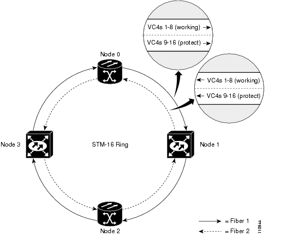
In two-fiber MS-SPRings, each fiber is divided into working and protect bandwidths. For example, in an STM-16 MS-SPRing, VC4s 1 to 8 carry the working traffic, and VC4s 9 to 16 are reserved for protection ( Figure7-2). Working traffic (VC4s 1 to 8) travels in one direction on one fiber and in the opposite direction on the second fiber. CTC circuit routing routines calculate the shortest path for circuits based on many factors, including user requirements, traffic patterns, and distance. For example, in Figure7-2, circuits going from Node 0 to Node 1 will typically travel on Fiber 1, unless that fiber is full, in which case circuits will be routed to Fiber 2 through Node 3 and Node 2. Traffic from Node 0 to Node 2 (or Node 1 to Node 3) can be routed on either fiber, depending on circuit provisioning requirements and traffic loads.
Figure 7-2 Four-Node, Two-Fiber MS-SPRing
The SDH K1, K2, and K3 bytes carry the information that governs MS-SPRing protection switches. Each MS-SPRing node monitors the K bytes to determine when to switch the SDH signal to an alternate physical path. The K bytes communicate failure conditions and actions taken between nodes in the ring.
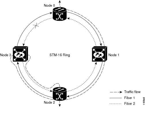
If a break occurs on one fiber, working traffic targeted for a node beyond the break switches to the protect bandwidth on the second fiber. The traffic travels in a reverse direction on the protect bandwidth until it reaches its destination node. At that point, traffic is switched back to the working bandwidth.
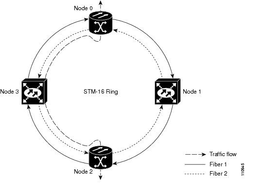
Figure7-3 shows a traffic pattern sample on a four-node, two-fiber MS-SPRing.
Figure 7-3 Four-Node, Two-Fiber MS-SPRing Traffic Pattern Sample
Figure7-4 shows how traffic is rerouted following a line break between Node 0 and Node3.
•
•
Figure 7-4 Four-Node, Two-Fiber MS-SPRing Traffic Pattern Following Line Break
7.2.1 MS-SPRing Bandwidth
MS-SPRing nodes can terminate traffic coming from either side of the ring. Therefore, MS-SPRings are suited for distributed node-to-node traffic applications such as interoffice networks and access networks.
MS-SPRings allow bandwidth to be reused around the ring and can carry more traffic than a network with traffic flowing through one central hub. MS-SPRings can also carry more traffic than an SNCP operating at the same STM-N rate. Table7-1 shows the bidirectional bandwidth capacities of two-fiber MS-SPRings. The capacity is the STM-N rate divided by two, multiplied by the number of nodes in the ring minus the number of pass-through VC4 circuits.
Table 7-1 Two-Fiber MS-SPRing Capacity
STM-16
VC4 1-8
VC4 9-16
8 x N - PT
STM-64
VC4 1-32
VC4 33-64
32 x N - PT
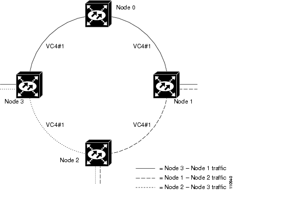
Figure7-5 shows an example of MS-SPRing bandwidth reuse. The same VC4 carries three different traffic sets simultaneously on different spans around the ring: one set from Node 3 to Node 1, another set from Node1 to Node 2, and another set from Node 2 to Node 3.
Figure 7-5 MS-SPRing Bandwidth Reuse
7.2.2 MS-SPRing Fiber Connections
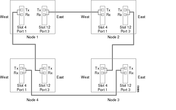
Plan your fiber connections and use the same plan for all MS-SPRing nodes. For example, make the east port the farthest slot to the right and the west port the farthest slot to the left. Plug fiber connected to an east port at one node into the west port on an adjacent node. Figure7-6 shows fiber connections for a two-fiber MS-SPRing with trunk (span) cards in Slot 4 (west) and Slot 12 (east). Refer to the CiscoONS15600SDH Procedure Guide for fiber connection procedures.
Note
Figure 7-6 Connecting Fiber to a Four-Node, Two-Fiber MS-SPRing
7.3 Subnetwork Connection Protection
Subnetwork connection protection (SNCP) rings provide duplicate fiber paths around the ring. Working traffic flows in one direction and protection traffic flows in the opposite direction. If a problem occurs in the working traffic path, the receiving node switches to the path coming from the opposite direction.
CTC automates ring configuration. SNCP traffic is defined within the ONS15600SDH on a circuit-by-circuit basis. If a path-protected circuit is not defined within a 1+1 LMSP or MS-SPRing line protection scheme and path protection is available and specified, CTC uses SNCP as the default. You can set up a maximum of 64STM-16 SNCPs or 16 STM-64 SNCPs for each ONS15600SDH node.
A SNCP circuit requires two data communications channel (DCC)-provisioned optical spans per node. SNCP circuits can be created across these spans until their bandwidth is consumed.
Note
The span bandwidth consumed by a SNCP circuit is two times the circuit bandwidth, since the circuit is duplicated. The cross-connection bandwidth consumed by a SNCP circuit is three times the circuit bandwidth at the source and destination nodes only. The cross-connection bandwidth consumed by an intermediate node has a factor of one.
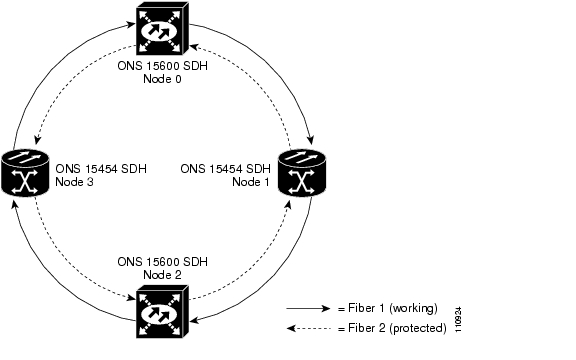
Figure7-7 shows a basic SNCP configuration. If Node 0 sends a signal to Node 2, the working signal travels on the working traffic path through Node 1. The same signal is also sent on the protect traffic path through Node 3.
Figure 7-7 Basic Four-Node SNCP
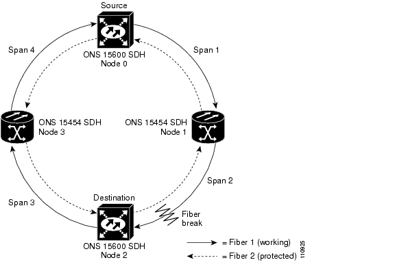
If a fiber break occurs, Node 2 switches its active receiver to the protect signal coming through Node 3 ( Figure7-8).
Figure 7-8 SNCP with a Fiber Break
Because each traffic path is transported around the entire ring, SNCPs are best suited for networks where traffic concentrates at one or two locations and is not widely distributed. SNCP capacity is equal to its bit rate. Services can originate and terminate on the same SNCP, or they can be passed to an adjacent access or interoffice ring for transport to the service-terminating location.
7.4 Subtending Rings
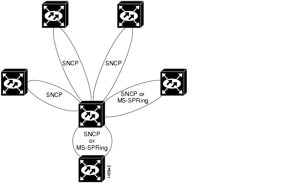
Subtending rings reduce the number of nodes and cards required and reduce external shelf-to-shelf cabling. The ONS15600SDH supports ten concurrent rings. Figure7-9 shows an ONS15600SDH with multiple subtending rings.
Figure 7-9 ONS 15600 SDH with Multiple Subtending Rings
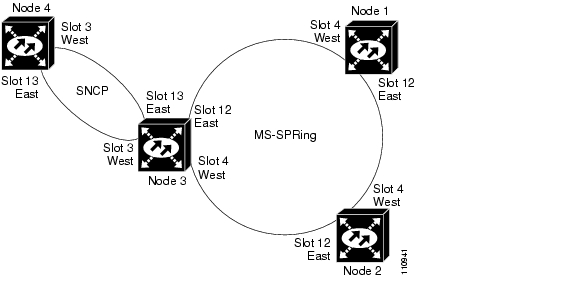
Figure7-10 shows an SNCP subtending from an MS-SPRing. In this example, Node 3 is the only node serving both the MS-SPRing and SNCP. STM-N cards in Slots 4 and 12 serve the MS-SPRing, and STM-N cards in Slots 3 and 13 serve the SNCP.
Figure 7-10 SNCP Subtending from an MS-SPRing
The ONS15600SDH can support 16 MS-SPRings on the same node. This capability allows you to deploy an ONS15600SDH in applications requiring SDH digital cross-connect systems (DCSs) or multiple SDH ADMs.
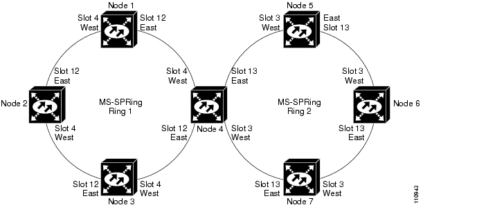
Figure7-11 shows two MS-SPRings shared by one ONS15600SDH. Ring 1 runs on Nodes 1, 2, 3, and 4. Ring 2 runs on Nodes 4, 5, 6, and 7. Two MS-SPRings, Ring 1 and Ring 2, are provisioned on Node4. Ring 1 uses cards in Slots 4 and 12, and Ring 2 uses cards in Slots 3 and 13.
Note
Figure 7-11 MS-SPRing Subtending from an MS-SPRing
After subtending two MS-SPRings, you can route circuits from nodes in one ring to nodes in the second ring. For example, in Figure7-11 you can route a circuit from Node 1 to Node 7. The circuit would normally travel from Node 1 to Node 4 to Node 7. If fiber breaks occur, for example between Nodes 1 and 4 and Nodes 4 and 7, traffic is rerouted around each ring: in this example, Nodes 2 and 3 in Ring 1 and Nodes5 and 6 in Ring 2.
7.5 Extended SNCP Mesh Networks
In addition to single MS-SPRings, SNCPs, and ADMs, you can extend ONS15600SDH traffic protection by creating extended SNCP mesh networks. Extended SNCP rings include multiple ONS15600SDH topologies and extend the protection provided by a single SNCP to the meshed architecture of several interconnecting rings.
In an extended SNCP ring, circuits travel diverse paths through a network of single or multiple meshed rings. When you create circuits, CTC automatically routes circuits across the Extended SNCP ring, or you can manually route them. You can also choose levels of circuit protection. For example, if you choose full protection, CTC creates an alternate route for the circuit in addition to the main route. The second route follows a unique path through the network between the source and destination and sets up a second set of cross-connections.
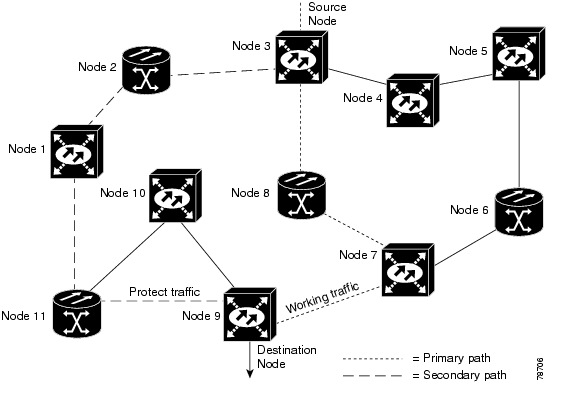
For example, in Figure7-12, a circuit is created from Node 3 to Node 9. CTC determines that the shortest route between the two nodes passes through Node 8 and Node 7, shown by the dotted line, and automatically creates cross-connections at Nodes 3, 8, 7, and 9 to provide the primary circuit path.
Figure 7-12 Extended SNCP Mesh Network
If full protection is selected, CTC creates a second unique route between Nodes 3 and 9 that passes through Nodes 2, 1, and 11. Cross-connections are automatically created at Nodes, 3, 2, 1, 11, and 9, shown by the dashed line. If a failure occurs on the primary path, traffic switches to the second circuit path. In this example, Node 9 switches from the fiber from Node 7 to the fiber from Node 11 and service resumes. The switch occurs within 50 ms.
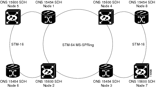
Extended SNCP rings also allow spans of different SDH line rates to be mixed together in virtual rings. Figure7-13 shows Nodes 1, 2, 3, and 4 in an STM-64 ring.
Figure 7-13 Extended SNCP Virtual Ring
![]()
![]()
![]()
![]()
![]()
![]()
![]()
![]()
Posted: Thu Feb 26 17:39:35 PST 2004
All contents are Copyright © 1992--2004 Cisco Systems, Inc. All rights reserved.
Important Notices and Privacy Statement.