|
|

Table Of Contents
Configuring Network Management
LAN Connection for the Network Management Station
Configuring the BPX Switch LAN and IP Relay
Configuring the Cisco WAN Manager Workstation
Configuring Network Management
A permanent network management station (NMS) enables you to use Cisco's network management software, including CiscoView and Cisco WAN Manager. For many configuring and provisioning tasks, you may find the graphical interface more convenient than the command line interface.
During the initial setup of the BPX node, you temporarily connected a terminal or Cisco WAN Manager workstation to the control port, as required for initial power-up. However, this temporary control port connection is not used in normal operation. This chapter explains how to connect a permanent network management station to the LAN port.
(Of course, you can always access the BPX switch through a local control port over an RS-232 or Ethernet TCP/IP link. You use an administration screen from a control terminal or from the Cisco WAN Manager Network Management Station (NMS) to issue BPX switch commands.)
To connect a permanent network management station, you must configure both the nodes and the
Cisco WAN Manager workstation.This chapter covers these initial procedures to set up a permanent network management station.
Contents of this chapter include:
•
Configuring the BPX Switch LAN and IP Relay
•
•
•
For remote control terminal access, you can use a Virtual Terminal (vt) command provided that the node has been configured with a name and at least one trunk to the network has been established.
When an IGX is configured as an Interface Shelf, it cannot be reached by the vt command. For this reason, you must configure Frame Relay end-to-end connections from the Cisco WAN Manager via the Connection Manager over an in-band LAN connection.
However, Telnet can be used to access an interface shelf (such as an IGX shelf, MGX 8220, or MGX 8800 shelf) if a Cisco WAN Manager workstation is not available to provide inband management.
You can monitor, manage, and troubleshoot the BPX switch by using the Cisco WAN Manager Network Management Station. You issue commands to a BPX switch through the Node Administration window.
You use Cisco WAN Manager's Connection Manager to provision and perform end-to-end configuration management for Frame Relay connections in both tiered and nontiered networks.You can display and monitor the network's topology, monitor alarms, events, and statistics. For more information, refer to the Cisco WAN Manager User's Guide.
For an overview of BPX network management software, including WAN Manager, see "The BPX Switch: Functional Overview."
For details about using the command line interface (CLI) to perform initial NMS setup, refer to the Cisco WAN Switching Command Reference.
LAN Connection for the Network Management Station
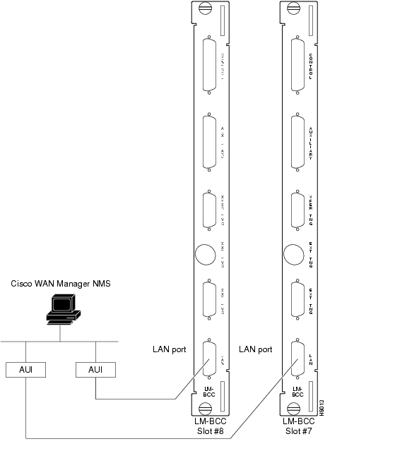
You connect the Cisco WAN Manager Network Management Station to an Ethernet port (LAN port) on a node in the network. The LAN port provides the capacity necessary for network management traffic and network statistics collection. The LAN connection is illustrated in Figure 20-1.
For access to the node using an Internet connection, you must use the cnflan command to enter:
•
•
•
•
Figure 20-1 LAN Connections to BCC Back Cards, LM-BCCs Shown
Configuring the BPX Switch LAN and IP Relay
In setting up network management for a network, you must configure both the Cisco WAN Manager workstation and network nodes.
Cisco WAN Manager communicates over a standard physical LAN network to a gateway node or nodes, but you must setup a separate in-band IP relay network for all nodes via a gateway node for SNMP and TFTP inband communication over the node trunks.
During the configuration of BPX switch interfaces, you must make sure that the following parameters are consistently set with your local area network (Ethernet LAN):
•
•
•
To set the parameters, use the BPX switch commands as described in Table 20-1. On BPX and IGX switches, use these commands to configure the nodes for operation with Cisco WAN Manager.
Table 20-1 BPX Switch Commands
cnflan
Configures the BPX switch BCC LAN port IP address and subnet mask. This SuperUser command is necessary only for nodes or shelves in which the LAN port is actually connected to a physical Ethernet LAN as shown in Figure 20-2.
cnfsnmp
Configures the following SNMP Get and Set community strings for the BPX switch:
•
•
•
cnfnwip
Configures the virtual IP network (IP relay) among BPX switches. This is a Superuser command.
cnfstatmast
Defines the IP address for routing messages to and from the Statistics Manager in CiscoView.
For more information on how to use these commands, refer to the Cisco WAN Switching Command Reference or the Cisco WAN Switching SuperUser Command Reference. SuperUser commands may be used only by authorized personnel with great care.
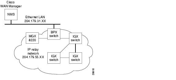
Figure 20-2 Cisco WAN Manager Physical LAN and IP Relay Network
Configuring the Cisco WAN Manager Workstation
To configure the Cisco WAN Manager workstation, use the following procedure:
Step 1
Note
Step 2
beacon% more /etc/hosts## Sun Host Database## If the NIS is running, this file is only consulted when booting#127.0.0.1 localhost#204.179.61.121 beacon loghost# node physical ethernet LAN addresses204.179.61.104 nw1bpx1p204.179.61.71 nw1axi1p# node ip relay addresses204.179.55.101 nw1ipx1204.179.55.102 nw1ipx2204.179.55.103 nw1ipx3204.179.55.123 nw1igx1204.179.55.111 nw1bpx1204.179.55.105 nw1axi1If the workstation is connected to the corporate network for access to hosts on another network, add any IP addresses and associated names of the hosts that you may want to connect to your workstation, because the NIS is disabled.
Step 3
Note
0|Network1|nw1bpx1p|9600|0|7|6|0|30|1024|9.1|
or
0|Network1|204.179.61.104|9600|0|7|6|0|30|1024|9.1|
Step 4
/etc/rc2.d/S72inetsvcfile:vi /etc/rc2.d/S72inetsvc/usr/sbin/route add "224.0.0.0 ...................{this is already there# route add for Cisco WAN Managerroute add net 204.179.55.0 204.179.61.104 1
Note
Configuring the LAN Port
For instructions on configuring the Cisco WAN Manager workstation, refer to the Cisco WAN Manager User's Guide. For command definitions, refer to the Cisco WAN Switching Command Reference.
Note
To configure the LAN port, use the following procedure:
Step 1
Normally, the System Administrator will provide the IP addresses for the workstation and node.
The addresses shown are just examples. Use the addresses obtained from your System Administrator. (This example is for a workstation named "hedgehog" at address 192.187.207.200. It also assumes that the BPX or IGX switch LAN port for node sanfran has been assigned an IP address of 192.187.210.30 and a host name of sanfran. Your own host name and addresses are different.)
192.187.207.200 hedgehog192.187.210.30 sanfran
Note
Note
Step 2
The cnflan command configures the node's communication parameters so that the node can communicate with a Cisco WAN Manager terminal over an Ethernet LAN using the TCP/IP protocol. The parameters contain address information about the Ethernet TCP/IP network that is used to connect the Cisco WAN Manager station to an IGX or BPX switch. The values used must conform to those of the network and should be supplied by the Ethernet network administrator.
The parameters for the cnflan command are described in Table 20-2.
A cnflan screen is shown in the following example for the LAN setup shown in Figure 20-3.
An IP address of 192.187.210.30 has been entered as the active IP address for the node. The IP Subnet mask is entered as 255.255.255.0 for a Class C LAN network.
The TCP service port is entered as 5120.
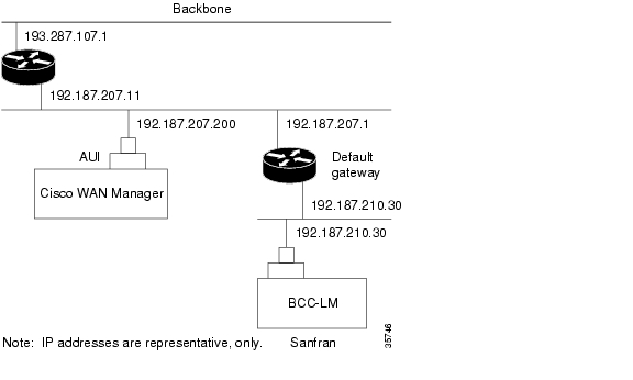
Because the workstation and node are on different networks in this example, a gateway address of 192.187.207.1 (the address of the node serving as a gateway for Cisco WAN Manager, in this example), has been entered. You must obtain this gateway address from your System Administrator. If the workstation and node are both on the same network, no gateway address is needed.
The "Maximum LAN Transmit Unit" and "Ethernet Address" parameters are not configurable by the cnflan command.
The "Ethernet Address" is a hardware address that is different for every node controller card, such as BCC.
The following is an example of configuring a control port (gateway router example):
beta TN YourID.1 BPX 15 9.3 July 3 2000 02:16 PSTActive IP Address: 192.187.210.30IP Subnet Mask: 255.255.255.0IP Service Port: 5120Default Gateway IP Address: 192.187.207.1Maximum LAN Transmit Unit: 1500Ethernet Address: 00.C0.43.00.00.20Type StateTCP UNAVAILUDP READYTelnet READYThis Command: cnflanEnter IP Address:Step 3
Step 4
config.svfile, you would enter the following at the Cisco WAN Manager workstation:ping sanfranFigure 20-3 Cisco WAN Manager LAN Connection via Gateway Router to a BPX Switch
Step 5
beta TN YourID BPX 15 9.3 July 3 2000 02:11 PSTActive Network IP Address: 192.187.57.10Active Network IP Subnet Mask: 255.255.255.192This Command: cnfnwipEnter active network IP address:Also, at the workstation, the /etc/hosts table and routing must be set up for each node in the network. This enables network management using SNMP and statistics collection using TFTP via inband ILMI.
Assuming an isolated network for the nodes, the workstation must be isolated from the NIS reference pages so that the Cisco WAN Manager workstation consults the /etc/hosts table. For more information, refer to the Cisco WAN Manager User's Guide.
Step 6
beta TN YourID.1 BPX 15 9.3 July 3 1998 02:16 PSTActive IP Address: 192.187.210.30IP Subnet Mask: 255.255.255.0IP Service Port: 5120Default Gateway IP Address: 192.187.207.1Maximum LAN Transmit Unit: 1500Ethernet Address: 00.C0.43.00.00.20Control Socket - ReadyOpen Socket Descriptor - 2Last Command: dsplanNext Command:"Sockets" is the BSD UNIX name for connections between processes, typically used in network communication.
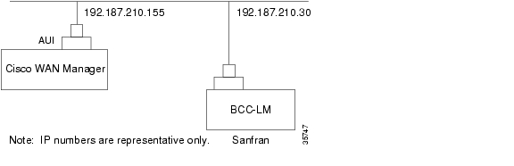
Figure 20-4 shows an example of a Cisco WAN Manager workstation LAN connection to a BPX switch on a network with no gateway router, nor connection to another LAN. This type of LAN connection could also be connected through a "Hub" which is essentially a signal splitter (passive or active).
Figure 20-4 Cisco WAN Manager LAN Connection to a BPX Switch (no gateway)
Controlling External Devices
If your system is configured to control an external device, such as a multiplexer, you can establish a window session to it from the control terminal. While in a window session, any characters you type at the control terminal go to the external device for processing. Any characters generated by the external device appear on the control terminal screen.
The Window to External Device (window) command establishes a window session. You can use this command only if the external device connects to the local node. You can, however, enter the window command during a virtual terminal session so that you have a window session with any external device in the network.
To start a window session, use the following procedure:
Step 1
Step 2
Step 3
Step 4
window [a | c]Step 5
Enter c if the device is attached to the node's Control Terminal port. The default for this parameter is Aux Port.
Step 6
window cStep 7
While in the window session, only commands used to control the external device are recognized. IGX/BPX commands are not recognized. You might notice a slight transfer delay in transmission, due to the IGX/BPX bundling of characters before transmitting them. Transfers are delayed until the transfer buffer is filled, or until the keyboard has been inactive for over 50 milliseconds.
To end a window session, enter an escape sequence.
Escape sequences are one to eight characters in length. You configure escape sequences by using the Configure Terminal Port Function (cnftermfunc) command. For example, if you have specified "signoff" as the escape sequence in the Configure Terminal Port Function, enter the following to end the window session:
signoffThe default escape sequence is:
^^ (SHIFT 66)If this escape sequence does not work and you do not know the configured escape sequence, leave the keyboard idle for four minutes. After four minutes, the system terminates the window session.
![]()
![]()
![]()
![]()
![]()
![]()
![]()
![]()
Posted: Tue May 10 21:17:29 PDT 2005
All contents are Copyright © 1992--2005 Cisco Systems, Inc. All rights reserved.
Important Notices and Privacy Statement.