|
|

This chapter provides an overview of VCO/4K call and supervision processing. The functions of Class of Service (COS), inpulse and outpulse rules, and answer supervision templates are summarized and tied together in a general call flow example. This chapter also establishes the system's relationship to connected equipment, and explains standard terminology.
For more information on call and supervision processing, refer to the following chapters:
Because of its flexible architecture, the VCO/4K can be connected to a wide variety of telecommunication equipment. Depending upon the equipment to which it is connected, system interfaces, called "ports," can be discussed in general terms. These terms describe how a port is used in an application and handled by the system software. Incoming and outgoing describe a port's relation to the call flow through the system. Three types of implementations—line-side, trunk-side, and mixed—indicate the position of the VCO/4K relative to the central office (CO) and connected equipment.
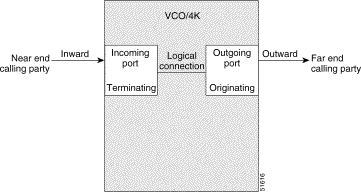
The terms used to describe signaling and supervision throughout this document relate to the direction of the call flow. Calls initiated outside the VCO/4K enter the system on incoming ports. The system initiates calls out of the system over outgoing ports. Incoming ports are sometimes referred to as terminating connections, while outgoing ports provide originating connections.
Using the simple call scenario in "Network Signaling Overview," the call attempt from the calling party causes an inward seizure on a system incoming port (call seizures are defined in "Call Supervision Signaling and Supervision Timing"). The system then selects an outgoing port to route the call to the called party and seizes outward.
The system establishes a complete call path between both parties using a logical connection to link the incoming and outgoing ports. Because the equipment connected to the system may be automated equipment rather than human parties, the general terms near end and far end equipment are used. Each of these terms and their relationship to the call flow through the system are summarized in Figure 2-1.
A system implementation defines the positioning of the VCO/4K in reference to the central office (CO). The system can be equipped with hardware components and software feature packages that support a desired implementation. The process of selecting the proper components is called configuring the system. A system can be configured for line-side, trunk-side and mixed.
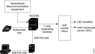
A line-side implementation indicates that the system is positioned between telephone stations or other pieces of ancillary equipment and the CO. Line-side implementation implies that the system sits in front of the CO (see Figure 2-2). One-way originating facilities link the system to the CO.
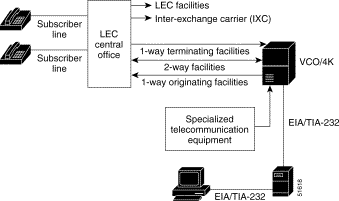
A trunk-side implementation means that the telephone stations are routed through the CO before being directed over trunks to the system for processing. Trunk-side implementation implies that the system sits behind the CO (see Figure 2-3). One-way terminating and originating, and/or two-way facilities link the system to the CO.
The system can also be configured for mixed line-side and trunk-side implementation. Some telephone stations can be directly connected to the system while others are also routed through a CO to the system.
Call processing within the system is accomplished using the information stored in the system database. Host commands may initiate system actions and host reports provide overall tracking of call handling, whereas step-by-step call processing is performed at the system level.
The key instructions for call processing on a port-by-port, call-by-call basis are defined in the following areas:
Class of Service (COS) is a set of operating characteristics that you assign to a network interface circuit (line/trunk port). The COS mark is entered into the system database and determines how a port can be used in a call. Table 2-1 summarizes the COS marks supported by the system.
| COS | Description |
|---|---|
O | Originating—Calls originating from the system; outgoing calls initiated by host command. |
T | Terminating—Calls terminating at the system; incoming calls initiated by actions outside the system. |
2 | 2-Way—Calls originating from the system or calls terminating at the system; outgoing calls initiated by host command, incoming calls initiated by outside actions. |
AO | Always Off Hook and Originating—Calls originating from the system, port goes off hook at system reset and remains off hook; outgoing calls initiated by host command. |
AT | Always Off Hook and Terminating—Calls terminating at the system, port goes off hook at system reset and remains off hook; incoming calls initiated by outside actions or forced by host command. |
A2 | Always Off Hook and 2-Way—Calls originating from the system or calls terminating at the system, port goes off hook at system reset and remains off hook; outgoing calls initiated by host command, incoming calls initiated by outside actions or forced by host command. |
Always off hook marks accommodate station equipment that is not capable of going on hook or remains off hook much of the time (such as operator/attendant stations). System call processing also uses internal COS marks for ports designated as 2-way, ports involved in a call using a virtual port, or any line/trunk port involved in a conference. Refer to the Cisco VCO/4K System Administrator's Guide for more information on standard and internal COS options.
An inpulse rule is a list of tokens defined by an application designer. Up to 16 tokens can be used to condition a trunk to wait for supervision events; collect MF, DTMF, or Dial Pulse (DP) digits; and store received digit fields in an internal system call record. An inpulse rule can also specify to execute an outpulse rule as part of inpulse rule processing; when the outpulse rule has been completed, processing continues. Categories of inpulse rules and their meanings are as follows:
An outpulse rule is a listing of tokens defined by an application designer. Up to 16 tokens can be used to condition a trunk to wait for supervision events, and outpulse MF/DTMF digits. An outpulse rule can also specify to execute an inpulse rule as part of outpulse rule processing; when the inpulse rule has been completed, processing continues. Categories of outpulse rules and their meanings are as follows:
Supervision processing is performed by a combination of supervision control outpulse rule tokens and answer supervision templates. The outpulse rule tokens WAIT SUP [xx] and FINAL SUP [xx] are used for intermediate supervision and final supervision, respectively. During outpulse rule processing, these tokens call specific answer supervision templates in much the same way a command calls a rule. The templates indicate which signaling events may be detected and the system response to each event. When an event is detected, the system response specified in the template is performed; the supervision control outpulse rule token is satisfied and rule processing continues.
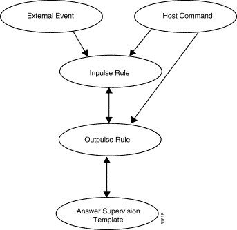
Template processing fits within the standard system call processing hierarchy (see Figure 2-4). Outpulse rule processing begins when a DO ORULE token is executed in an inpulse rule, or when an Outgoing Port Control ($69) or Incoming Port Control ($6A) command specifies an outpulse rule. WAIT SUP [xx] tokens cause outpulse rule processing to wait while answer supervision template processing takes place. When template processing ends, outpulse rule processing continues. FINAL SUP [xx] tokens act as setup tokens and do not suspend outpulse rule processing. These tokens define final supervision template processing after outpulse rule processing ends. Answer supervision templates and their interaction with outpulse rules are discussed in "Call Examples."
A typical call involves a logical connection between two network interface circuits. The signaling generated and detected by the system that controls the handling of this connection is called supervision processing. This general call flow and the portions of the flow involving supervision processing are shown in Figure 2-5.
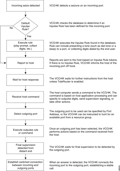
When an incoming port seizes inward, the system attempts to create a logical connection between this port and an outgoing port. If a default inpulse rule is defined for the incoming port, this rule may contain tokens which send supervision signals toward the near-end connected equipment. Supervision signaling in this case usually requests additional information from the incoming equipment for processing the call.
Based on the system application, the host may issue commands, request reports, and execute inpulse and outpulse rules during the course of call processing. In most cases, the host will issue a resource control command that selects an outgoing port and executes an outpulse rule. The outpulse rule seizes out on an outgoing line/trunk and waits to detect supervision signals from the far end. Answer supervision templates, specified by tokens in the outpulse rule, are processed during this waiting period. Each template contains a set of system responses to the detection of certain supervision signals.
The signals detected during answer supervision template processing may be call supervision signals (changes in the on-hook/off-hook status of the connected equipment) or audible call progress tones. The templates also allow expiration of supervision timers to affect supervision processing. Collectively, supervision signals, tones and timers are referred to as supervision events.
Template processing can occur during both intermediate and final supervision periods.
Intermediate supervision, in standard network terms, refers to all supervision signaling prior to final answer. Intermediate supervision normally determines if the equipment at the far end can respond to the call; this supervision precedes system actions such as digit outpulsing.
Final supervision refers to any supervision event that indicates the far end has answered the call (usually causing answerback to be passed to the near end and initiating billing).
In most cases, intermediate supervision detection occurs during outpulse rule processing; the wait for final supervision takes place after rule processing completes. However, the flexibility of answer supervision templates allows you to make the detection of any supervision event generate answerback, initiate billing, and end rule processing at any point during the call.
Once the system detects a supervision event that identifies a far-end answer, the system establishes a stable call. A stable call involves a logical connection between the incoming and outgoing port, and a voice path between the near end and far end.
![]()
![]()
![]()
![]()
![]()
![]()
![]()
![]()
Posted: Sat Sep 28 14:39:22 PDT 2002
All contents are Copyright © 1992--2002 Cisco Systems, Inc. All rights reserved.
Important Notices and Privacy Statement.