|
|

This chapter provides a fundamental understanding of network signaling and establishes standard terminology used throughout this document. The topics covered in this chapter are:
 |
Note This information focuses on general network supervision processing, and does not include information pertinent to SS7 system configurations. For information pertaining to SS7 operations, refer to the appropriate ANSI or ITU SS7 manual for the VCO/4K. |
Signaling events occurring during network call processing may be divided into two basic categories: address signaling and supervisory signaling.
Address signaling is the means by which a subscriber or switching system inputs dialed number information into the network. In some applications, the telephone equipment outputs automatic number identification (ANI) information into the network following an off-hook. Typically address signaling is accomplished by dial pulsing or by in-band signaling with DTMF and MF tones. This information must often be transmitted over several links in the switched network to establish a voice path between the caller and the called party.
 |
Note This document discusses supervision signaling surrounding the collection and transmitting of address information. Techniques and formats specific to address signaling, however, are beyond the scope of this document and are not examined in detail. |
Supervision information may be indicated using both in-band and out-of-band supervisory signals. Supervisory signaling is divided into three categories: call supervision, alert signaling and call progress tones.
Call supervision detects or changes the state or condition of a line or trunk (via out-of-band signaling). There are two possible supervised conditions: on-hook and off-hook. On-hook means telephone equipment is idle; off-hook occurs when telephone equipment is active.
When a line/trunk goes off-hook, it is interpreted as a seizure by the system, and the line/trunk's operating state goes from idle to active. Both ends of a voice path must be off-hook for two-way communication to occur. If one end of the path goes on-hook and the other remains off-hook, the voice path becomes unidirectional (near- or far-end disconnect). The calling party can input control information to dial another number. When both ends of the path go on-hook, the voice path is torn down in the network.
Brief changes in the on-hook/off-hook status of a line or trunk (wink or hook flash signals) are also viewed as call supervision signals in this document. Seizures, wink and hook flash signals, and answer conditions are discussed in "Call Supervision Signaling and Supervision Timing."
The most familiar alert signal is power ringing, which notifies a called party of an incoming call. Ringing is initiated by applying ring voltage (50 to 130 V @ 20/30 Hz) to the line or trunk (out-of-band signaling). Ring voltage is normally obtained from a ring generator which is wired to the switching system. The far end central office provides audible ringback (an in-band call progress tone) toward the calling party to indicate that ring voltage has been applied to the circuit.
Power ringing is discussed "Call Supervision Signaling and Supervision Timing." Audible ringback tone is grouped with other call progress tones and is discussed in "Call Progress Tones."
Signals in this category include audible tones that indicate the progress of a telephone call to a calling party. The Bell system uses a Precise Tone Plan consisting of four frequencies: 350 Hz, 440 Hz, 480 Hz and 620 Hz. Call progress tones consist of these frequencies (either single or paired frequencies) and specific temporal patterns (cadences). The most common call progress tones are as follows:
The VCO/4K can directly interface with T1 digital carrier systems operating at a DSX 1 level. Each T1 span supports twenty-four 56-Kbps voice channels and complies with Bell System DSX 1 specifications for transmission at 1.544 Mbps. Transmission over T1 circuits is bidirectional, involving both a transmit (Tx) and receive (Rx) data stream.
For complete descriptions of digital interfaces, refer to:
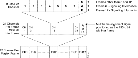
The DS-1 1.544-Mbps bit stream transmits 24 separate channels of pulse code modulation (PCM) voice or digital data. Each channel is transmitted 8 bits at a time. All 24 channels are grouped together to form a group of 192 bits. For synchronization (framing) purposes, every group of 192 bits ends with a framing bit. The 193 bits constitute a frame and twelve frames are grouped together to form a master frame.
Under D3/D4 format, every sixth or twelfth frame of the master frame contains signaling information. The signaling information pertaining to each channel is presented in bit 8. Figure 1-1 shows the framing schedule for DS-1, D3 format digital transmission.

The D3/D4 format for DS-1 (1.544 Mbps) bit streams assigns every sixth and twelfth frame as a "signaling" frame, wherein the eighth bit of each 8-bit channel sample (the Least Significant Bit) is reserved for signaling. These bits are designated "A" (sixth frame) and "B" (twelfth frame).
Bit stream "signaling" frame locations are delineated by the framing-bit sequence. This sequence [100011011100] repeats every twelve frames; the bold framing bit in the sequence informs the terminal that this frame contains signaling data on the eighth bit of each channel (this technique is known as bit-robbing). The twelve frames comprising one full framing sequence are often referred to as a superframe.
The T1 interface uses the equivalent of E+M two-state signaling for supervision control. The signaling bits in the Rx data stream correspond to the states of the E lead, while the signaling bits in the Tx data stream represent M lead states. Interoffice supervision is primarily conveyed via the "A" bits in both Rx and Tx directions. The "B" bits in the Rx data streams are not currently interpreted by the systems.
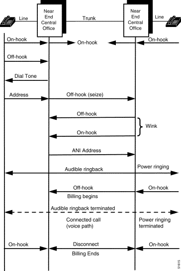
The types and sequences of signals exchanged between connected equipment varies according to equipment type, service/application provided, point of time during the call, and other variables. During application development, signaling requirements are normally defined in the early stages or even before any work is performed. Figure 1-2 illustrates the signaling sequence during a plain old telephone service (POTS) subscriber call. The calling party goes off-hook, receives dial tone, and dials address digits. The near-end CO collects the digits and seizes out on an outgoing trunk to the far end CO. When the far-end CO is ready to receive the forwarded digits, it sends a wink signal to the near-end CO, which then outpulses the address digits. The far-end CO rings the called party's phone and supplies audible ringback to the calling party.
When the called party goes off-hook, the far-end CO sends answer supervision to the near-end CO. The power ringing and audible ringback are terminated and a stable call is established between the two parties. Either party can end the connection by going on-hook; the network circuit is then torn down.

![]()
![]()
![]()
![]()
![]()
![]()
![]()
![]()
Posted: Sat Sep 28 14:39:18 PDT 2002
All contents are Copyright © 1992--2002 Cisco Systems, Inc. All rights reserved.
Important Notices and Privacy Statement.