cc/td/doc/product/ong/15400/r60docs
hometocprevnextglossaryfeedbacksearchhelp
PDF

Table Of Contents

Configuring Ethernet over MPLS

Understanding EoMPLS

EoMPLS Support

EoMPLS Restrictions

EoMPLS Quality of Service

Configuring EoMPLS

EoMPLS Configuration Guidelines

VC Type 4 Configuration on PE-CLE Port

VC Type 5 Configuration on PE-CLE Port

EoMPLS Configuration on PE-CLE SPR Interface

Bridge Group Configuration on MPLS Cloud-facing Port

Setting the Priority of Packets with the EXP

EoMPLS Configuration Example

Monitoring and Verifying EoMPLS


Configuring Ethernet over MPLS


This chapter describes how to configure Ethernet over Multiprotocol Label Switching (EoMPLS) on the ML-Series card.

This chapter includes the following major sections:

Understanding EoMPLS

Configuring EoMPLS

EoMPLS Configuration Example

Monitoring and Verifying EoMPLS

Understanding EoMPLS

EoMPLS provides a tunneling mechanism for Ethernet traffic through an MPLS-enabled Layer 3 core. It encapsulates Ethernet protocol data units (PDUs) inside MPLS packets and using label stacking forwards them across the MPLS network. EoMPLS is an Internet Engineering Task Force (IETF) standard-track protocol based on the Martini draft, specifically the draft-martini-l2circuit-encap-mpls-01 and draft-martini-l2circuit-transport-mpls-05 sections.

EoMPLS allows service providers to offer customers a virtual Ethernet line service or VLAN service using the service provider's existing MPLS backbone. It also simplifies service provider provisioning, since the provider edge customer-leading edge (PE-CLE) equipment only needs to provide Layer 2 connectivity to the connected customer edge (CE) equipment.

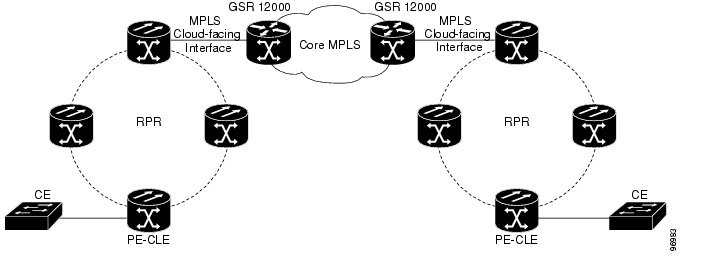
Figure 18-1 shows an example of EoMPLS implemented on a service provider network. In the example, the ML-Series card acts as PE-CLE equipment connecting to the Cisco GSR 12000 Series through an RPR access ring. Point-to-point service is provided to CE equipment in different sites that connect through ML-Series cards to the ML-Series card RPR access ring.

Figure 18-1 EoMPLS Service Provider Network

Implementing EoMPLS on a service provider network requires ML-Series card interfaces to play three major roles. The ML-Series card interface roles must be configured on both sides of the EoMPLS point-to-point service crossing the MPLS core.

ML-Series card interfaces connect the provider's network directly to the customer edge equipment and are known as the PE-CLE interfaces. This PE-CLE interface on the ML-Series card is FastEthernet or GigabitEthernet and is configured to be an endpoint on the EoMPLS point-to-point session.

An ML-Series card interface bridges the PE-CLE interface and the RPR network of ML-Series cards. This RPR/SPR interface contains POS ports and is configured for MPLS IP.

An ML-Series card interface connects to a core MPLS interface. This interface is GigabitEthernet or FastEthernet and connects to the port of a Cisco GSR 12000 Series or similar device that is on the MPLS network. This MPLS cloud-facing interface bridges the SPR interface and the MPLS cloud.

Implementing EoMPLS across a service provider's network requires setting up directed Label Distribution Protocol (LDP) sessions (LSPs) between the ingress and egress PE-CLE routers to exchange information for a virtual circuit (VC). Each VC consists of two LSPs, one in each direction, since an LSP is a directed path to carry Layer 2 frames in one direction only.

EoMPLS uses a two-level label stack to transport Layer 2 frames, where the bottom/inner label is the VC label and the top/outer label is the tunnel label. The VC label is provided to the ingress PE-CLE by the egress PE-CLE of a particular LSP to direct traffic to a particular egress interface on the egress PE-CLE. A VC label is assigned by the egress PE-CLE during the VC setup and represents the binding between the egress interface and a unique and configurative VC ID. During a VC setup, the ingress and egress PE-CLE exchange VC label bindings for the specified VC ID.

An EoMPLS VC on the ML-Series card can transport an Ethernet port or an IEEE 802.1Q VLAN over MPLS. A VC type 5 tunnels an Ethernet port and a VC type 4 transports a VLAN over MPLS. In a VC type 5 session, the user can expect any traffic that is received on an ML-Series card PE-CLE port with an mpls l2transport route command to be tunneled to the remote egress interface on the far-end ML-Series card PE-CLE port. With a VC type 4, a user can expect the tunnel to act as physical extension to that VLAN. The EoMPLS session commands are entered on a VLAN subinterface on the PE-CLE, and only VLAN-tagged traffic received on that port will be tunneled to the remote PE-CLE.

EoMPLS Support

EoMPLS on the ML-Series card has the following characteristics:

EoMPLS is only supported on FastEthernet and GigabitEthernet interfaces or subinterfaces.

MPLS tag switching is only supported on SPR interfaces.

Class of service (CoS) values are mapped to the experimental (EXP) bits in the MPLS label, either statically or by using the IEEE 802.1p bits (default).

The ingress PE-CLE ML-Series card sets the time-to-live field to 2 and the tunnel label to a value of 255.

Ingress PE-CLE ML-Series cards set the S bit of the VC label to 1 to indicate that the VC label is at the bottom of the stack.

Since EoMPLS traffic is carried over the RPR, whatever load balancing is applicable for the traffic ingressing RPR is also applicable for the EoMPLS traffic.

EoMPLS is supported over RPR under GFP-F framing and HDLC framing.

The Ethernet over MPLS feature is part of the Cisco Any Transport over MPLS (AToM) product set.

The ML-Series card hosting the EoMPLS endpoint ports must be running the MPLS microcode image to support EoMPLS. For more information on multiple microcode images, see the "Multiple Microcode Images" section on page 3-11. Other ML-Series cards in the RPR are not restricted to the MPLS microcode image.

EoMPLS Restrictions

EoMPLS on the ML-Series card has the following restrictions:

Packet-based load balancing is not supported. Instead, circuit-ID based load balancing is used.

Zero hop or hairpin VCs are not supported. A single ML-Series card cannot be both the source and destination for a VC.

MPLS control word for sequencing of data transmission is not supported. Packets must be received and transmitted without control word.

Sequence checking or resequencing of EoMPLS traffic is not supported. Both depend on the control word to function.

Maximum transmission unit (MTU) fragmentation is not supported.

Explicit-null label for back-to-back LDP sessions is not supported.


Caution Since MTU fragmentation is not supported across the MPLS backbone, the network operator must make sure the MTU of all intermediate links between endpoints is sufficient to carry the largest Layer 2 PDU.

EoMPLS Quality of Service

The EXP is a 3-bit field and part of the MPLS header. It was created by the IETF on an experimental basis, but later became part of the standard MPLS header. The EXP bits in the MPLS header carry the packet priority. Each label switch router along the path honors the packet priority by queuing the packet into the proper queue and servicing the packet accordingly.

By default, the ML-Series card does not map the IEEE 802.1P bits in the VLAN tag header to the MPLS EXP bits. The MPLS EXP bits are set to a value of 0.

There is no straight copy between Layer 2 CoS and MPLS EXP, but the user can use the set mpls experimental action to set the MPLS EXP bit values based on a match to 802.1p bits. This mapping occurs at the entry point, the ingress of the network.

Quality of service (QoS) for EoMPLS traffic on ML-Series cards uses strict priority and/or weighted round robin scheduling in the egress interface of both imposition and disposition router. This requires selection of the service class queue that determines the type of scheduling. In the imposition router, the priority bits EXP or RPR CoS that are marked based on policing are used to select the service class queue and in the disposition router, the dot1p CoS bits (which are copied from EXP bits of the labels) are used to do the same. In addition to scheduling in the egress interface, the output policy action can also include remarking of EXP and RPR CoS bits.

EoMPLS on the ML-Series card uses the Cisco Modular Quality of Service Command-Line Interface (MQC), just like the standard QoS on the ML-Series card. But the full range of MQC commands are not available. Table 18-1 lists the applicable MQC statements and actions for the ML-Series card interfaces.

Table 18-1 Applicable EoMPLS QoS Statements and Actions 

Interface
Applicable MQC Match Statements
Applicable MQC Actions

Imposition Ingress

match cos

match ip precedence

match ip dscp

match vlan

police cir cir-burst [pir-bust pir pir conform [set-mpls-exp | exceed [set-mpls-exp][violate set-mpls-exp]

Imposition Egress

match mpls exp

bandwidth {bandwidth-kbps | percent percent}

and

priority kbps

and

[set-mpls-exp]

Disposition Ingress

Not applicable

Not applicable

Disposition Egress

match mpls exp

bandwidth {bandwidth-kbps | percent percent}

and

priority kbps

and

set-cos cos-value


Configuring EoMPLS

The ML-Series peer cards on both endpoints of the EoMPLS point-to-point service must be configured. Perform the following configuration tasks to enable EoMPLS:

VC Type 4 Configuration on PE-CLE Port (Either VC type 4 or VC type 5 is required.)

VC Type 5 Configuration on PE-CLE Port (Either VC type 4 or VC type 5 is required.)

EoMPLS Configuration on PE-CLE SPR Interface (Required)

Bridge Group Configuration on MPLS Cloud-facing Port (Required)

Setting the Priority of Packets with the EXP

EoMPLS Configuration Guidelines

These are the guidelines for configuring EoMPLS:

Loopback addresses are used to specify the peer ML-Series card's IP address.

LDP configuration is required. The default Tag Distribution Protocol (TDP) will not work.

EoMPLS uses LDP targeted session between the ML-Series cards to create the EoMPLS VCs.

The MPLS backbone must use an Interior Gateway Protocol (IGP) routing protocol, for example, Intermediate System-to-Intermediate System (IS-IS) Protocol or Open Shortest Path First (OSPF).

Tag switching of IP packets must be enabled on the SPR interface for the PE-CLE ML-Series card.

VC Type 4 Configuration on PE-CLE Port

The customer-facing FastEthernet or GigabitEthernet port must be provisioned with EoMPLS and a VC type 4 or type 5. Interface GigE 0.1 on card A and card C plays the VC type 4 role in Figure 18-2. For more information on the role of a VC type 4, see the "Understanding EoMPLS" section.

To provision a VC type 4, which transport IEEE 802.1Q VLAN packets between two PE-CLE ML-Series cards, perform the following procedure on the customer facing port, beginning in global configuration mode:

 
Command
Purpose

Step 1 

Router(config)# mpls label protocol ldp

Specifies LDP as the label distribution protocol.

LDP must be specified. The ML-Series card does not operate EoMPLS with the default TDP as the label distribution protocol.

Step 2 

Router(config)# interface loopback0

Enters loopback interface configuration mode.

Step 3 

Router(config-if)# ip address ip-address 255.255.255.255

Assigns an IP address to the loopback interface. This loopback IP addresses is used to identify the peer in the EoMPLS point-to-point session.

No subnet mask is needed.

Step 4 

Router(config)# interface {GigabitEthernet | FastEthernet} interface-number.sub-interface- number

Specifies the Ethernet subinterface for the imposition interface. Make sure the subinterface on the adjoining CE equipment is on the same VLAN as this subinterface.

Step 5 

Router(config-subif)# no ip address

Disables the IP address if an IP address is assigned.

Step 6 

Router(config-subif)# encapsulation dot1Q vlan-id

Enables the subinterface to accept 802.1q VLAN packets. Make sure the VLAN ID is the same as the VLAN ID on the adjoining CE equipment.

Step 7 

Router(config-subif)# mpls l2transport route destination vc-id

or

xconnect destination vc-id encapsulation mpls

By entering the mpls l2transport route or the xconnect interface configuration command on a dot1Q VLAN sub-interface for VLAN-based EoMPLS, you can configure an EoMPLS tunnel to forward traffic based on the customer VLAN.

mpls l2transport route specifies the VC to use to transport the VLAN packets. Initiates a remote LDP session with the peer point-to-point endpoint interface.

destination specifies the loopback IP address for the remote ML-Series at the other end of the VC (PE-CLE).

vc-id is a value you supply. It must be unique for each VC. The VC ID is used to connect the endpoints of the VC. Specify the same VC ID on both ends of the VC.

xconnect binds the 802.1q VLAN circuit to a pseudowire for xconnect service. The encapsulation mpls pseudowire class parameter specifies MPLS for the tunneling method.

Note The xconnect command is a newer version of the mpls l2transport route interface configuration command.


Note Use the no mpls l2transport route destination vc-id or no xconnect destination vc-id encapsulation mpls interface command to delete the EoMPLS tunnel.


Step 8 

Router(config-subif)# end

Return to privileged EXEC mode.

Step 9 

Router# show mpls l2transport vc

Verify the configuration.

Step 10 

Router# copy running-config startup-config

(Optional) Save your entries in the configuration file

VC Type 5 Configuration on PE-CLE Port

The customer-facing FastEthernet or GigabitEthernet port must be provisioned with EoMPLS and a VC type 4 or type 5. Interface GigE 1 on card A and card C plays the VC type 5 role in Figure 18-2. For more information on the role of a VC type 5, see the "Understanding EoMPLS" section.

To provision a VC type 5, which transports the configured port's packets between two PE-CLE ML-Series cards, perform the following procedure on the customer facing port, beginning in global configuration mode:

 
Command
Purpose

Step 1 

Router(config)# mpls label protocol ldp

Specifies LDP as the label distribution protocol.

LDP must be specified. The ML-Series card does not operate EoMPLS with the default TDP as the label distribution protocol.

Step 2 

Router(config)# interface loopback0

Enters loopback interface configuration mode.

Step 3 

Router(config-if)# ip address ip-address 255.255.255.255

Assigns an IP address to the loopback interface. This loopback IP addresses is used to identify the peer in the EoMPLS point-to-point session.

No subnet mask is needed.

Step 4 

Router(config)# interface {GigabitEthernet | FastEthernet} interface-number


Specifies the Ethernet interface for the imposition interface.

Step 5 

Router(config-if)# no ip address

Disables the IP address if an IP address is assigned.

Step 6 

Router(config-subif)# mpls l2transport route destination vc-id

or

xconnect destination vc-id encapsulation mpls

By entering the mpls l2transport route or the xconnect interface configuration command on a VLAN for VLAN-based EoMPLS, you can configure an EoMPLS tunnel to forward traffic based on the customer VLAN.

mpls l2transport route specifies the VC to use to transport the VLAN packets. Initiates a remote LDP session with the peer point-to-point endpoint interface.

destination specifies the loopback IP address for the remote ML-Series at the other end of the VC (PE-CLE).

vc-id is a value you supply. It must be unique for each VC. The VC ID is used to connect the endpoints of the VC. Specify the same VC ID on both ends of the VC.

xconnect binds the 802.1q VLAN circuit to a pseudowire for xconnect service. The encapsulation mpls pseudowire class parameter specifies MPLS for the tunneling method.


Note The xconnect command is a newer version of the mpls l2transport route interface configuration command.


Note Use the no mpls l2transport route destination vc-id or no xconnect destination vc-id encapsulation mpls interface command to delete the EoMPLS tunnel.


Step 7 

Router(config-subif)# end

Return to privileged EXEC mode.

Step 8 

Router# show mpls l2transport vc

Verify the configuration.

Step 9 

Router# copy running-config startup-config

(Optional) Save your entries in the configuration file

EoMPLS Configuration on PE-CLE SPR Interface

To enable the RPR to act as an access ring for the MPLS cloud, you must provision the SPR interface on the same ML-Series card that hosts the EoMPLS PE-CLE FastEthernet or GigabitEthernet interfaces. Interface SPR 1 on card A and card C plays this role in Figure 18-2.

To provision the SPR interface for MPLS, perform the following procedure, beginning in global configuration mode:

 
Command
Purpose

Step 1 

Router(config)# mpls label protocol ldp

Specifies LDP as the label distribution protocol.

LDP must be specified. The ML-Series card does not operate EoMPLS with the default TDP as the label distribution protocol.

Step 2 

Router(config)# interface spr 1

Enters RPR interface configuration mode.

Step 3 

Router(config-if)# ip address ip-address mask

Assigns an IP address to the RPR interface for MPLS.

Step 4 

Router(config-if)# mpls ip

Implements tag switching on the SPR interface.

Step 5 

Router(config-if)# end

Exits interface configuration mode.

Step 6 

Router# copy running-config startup-config

Saves the running configuration file to the startup configuration file.

Bridge Group Configuration on MPLS Cloud-facing Port

A FastEthernet or GigabitEthernet port from an ML-Series card in the RPR must connect to the interface of a router that is part of the MPLS cloud. A bridge group must be created that contains this FastEthernet or GigabitEthernet port and the SPR subinterface. Interface GigE 0 on card B and card D plays this role in Figure 18-2.

To provision the MPLS cloud-facing port for EoMPLS, perform the following procedure, beginning in global configuration mode:

 
Command
Purpose

Step 1 

Router(config)# bridge bridge-group-number protocol {rstp | ieee}

(Optional) Assigns a bridge group number and defines the appropriate spanning-tree type: either IEEE 802.1D Spanning Tree Protocol or IEEE 802.1W Rapid Spanning Tree.

Step 2 

Router(config)# interface {GigabitEthernet | FastEthernet} interface-number

Enters interface configuration mode to configure the MPLS cloud-facing FastEthernet or GigabitEthernet interface of the ML-Series card.

Step 3 

Router(config-if)# bridge-group bridge-group-number

Assigns a network interface to a bridge group.

Step 4 

Router(config-if)# no shutdown

Changes the shutdown state to up and enables the interface.

Step 5 

Router(config)# interface spr 1.subinterface-number

Enters SPR subinterface configuration mode for the ML-Series card.

Step 6 

Router(config-if)# bridge-group bridge-group-number

Assigns the network interface to a bridge group.

Step 7 

Router(config-if)# end

Returns to privileged EXEC mode.

Step 8 

Router# copy running-config startup-config

(Optional) Saves your entries in the configuration file.

Setting the Priority of Packets with the EXP

Ethernet over MPLS provides QoS using the three EXP bits in a label to determine the priority of packets. To support QoS between ML-Series card point-to-point endpoints, set the experimental bits in both the VC and tunnel labels.

Perform the following steps to set the experimental bits:

 
Command
Purpose

Step 1 

Router(config)# class-map class-name

Specifies the user-defined name of the traffic class.

Step 2 

Router(config-cmap)# match any

Specifies that all packets will be matched.

Step 3 

Router(config-cmap)#end

Returns to global configuration mode.

Step 4 

Router(config)# policy-map policy-name

Specifies the name of the traffic policy to configure.

Step 5 

Router(config-pmap)# class class-name

Specifies the name of a predefined traffic class, which was configured with the class-map command, used to classify traffic to the traffic policy.

Step 6 

Router (config-pmap-c)# set mpls experimental imposition value

Designates the value to which the MPLS bits are set if the packets match the specified policy map.

Step 7 

Router(config)# interface GigabitEthernet interface-number

or

interface FastEthernet interface-number

Enters interface configuration mode.

Step 8 

Router(config-if)# service-policy input policy-name

Attaches a traffic policy to an interface.

EoMPLS Configuration Example

Figure 18-2 illustrates the sample network that the configuration commands reference. Examples 18-1, 18-2, 18-3, and 18-4 list relevant portions of the configuration files for enabling EoMPLS on ML-Series cards in a sample network.

Figure 18-2 EoMPLS Configuration Example

Example 18-1 ML-Series Card A Configuration

microcode mpls
ip subnet-zero
no ip domain-lookup
!
mpls label protocol ldp
!
interface Loopback0

ip address 10.10.10.10 255.255.255.255
!
interface SPR1
ip address 100.100.100.100 255.255.255.0
no keepalive
spr station-id 1
mpls ip
hold-queue 150 in
!
interface GigabitEthernet0
no ip address
!
interface GigabitEthernet0.1
encapsulation dot1Q 10
mpls l2transport route 3.3.3.3 1
!
interface GigabitEthernet1
no ip address
mpls l2transport route 4.4.4.4 2
!
interface POS0
no ip address
spr-intf-id 1
crc 32
!
interface POS1
no ip address
spr-intf-id 1
crc 32
router ospf 1
log-adjacency-changes
network 1.1.1.0 0.0.0.255 area 0
network 10.10.10.0 0.0.0.255 area 0
!
ip classless
no ip http server

Example 18-2 ML-Series Card B Configuration

bridge 10 protocol ieee
!
!
interface SPR1
no ip address
no keepalive
bridge-group 10
hold-queue 150 in
!
interface GigabitEthernet0
no ip address
bridge-group 10

Example 18-3 ML-Series Card C Configuration

microcode mpls
ip subnet-zero
no ip domain-lookup
!
mpls label protocol ldp
!
interface Loopback0

ip address 20.20.20.20 255.255.255.255
!
interface SPR1
ip address 100.100.100.100 255.255.255.0
no keepalive
spr station-id 4
mpls ip
hold-queue 150 in
!
interface GigabitEthernet0
no ip address
!
interface GigabitEthernet0.1
encapsulation dot1Q 10
mpls l2transport route 1.1.1.1 1
!
interface GigabitEthernet1
no ip address
mpls l2transport route 2.2.2.2 2
!
interface POS0
no ip address
spr-intf-id 1
crc 32
!
interface POS1
no ip address
spr-intf-id 1
crc 32
!
router ospf 1
log-adjacency-changes
network 1.1.1.0 0.0.0.255 area 0
network 10.10.10.0 0.0.0.255 area 0
!
ip classless
no ip http server

Example 18-4 ML-Series Card D Configuration

bridge 20 protocol ieee
!
!
interface SPR1
no ip address
no keepalive
bridge-group 20
hold-queue 150 in
!
interface GigabitEthernet0
no ip address
bridge-group 20

Monitoring and Verifying EoMPLS

Table 18-2 shows the privileged EXEC commands for monitoring and verifying EoMPLS.

Table 18-2 Commands for Monitoring and Maintaining Tunneling 

Command
Purpose
show mpls l2transport vc

Provides information about all EoMPLS tunnels.

show mpls l2transport vc detail

Provides detailed information about the EoMPLS tunnel.

show mpls l2transport vc vc-id

Provides information about a specific EoMPLS tunnel.


hometocprevnextglossaryfeedbacksearchhelp

Posted: Tue Oct 30 11:39:45 PDT 2007
All contents are Copyright © 1992--2007 Cisco Systems, Inc. All rights reserved.
Important Notices and Privacy Statement.