cc/td/doc/product/mels/15540x
hometocprevnextglossaryfeedbacksearchhelp
PDF

Table Of Contents

Safety Information and Preinstallation Tasks

Safety Information

Critical Safety Warnings

General Safety Precautions

Recommended Safety Precautions

Preventing ESD Damage

Required Equipment

System Requirements

Cable Requirements

Test Equipment Requirements

Before Installing

NTP-1 Unpack and Inspect the Shelf

Fiber Plant Characterization

Cleaning Information

Inspection Equipment

Cisco ONS 15540 ESPx Cleaning Kits

Inspecting the Cisco ONS 15540 ESPx Fiber Optic Connections


Safety Information and Preinstallation Tasks


This chapter describes safety information and procedures that should be performed prior to installation of hardware.

This chapter contains the following major sections:

Safety Information

Required Equipment

Before Installing

1 Unpack and Inspect the Shelf

Fiber Plant Characterization

Cleaning Information


Note Before you install, operate, or service the system, read the Regulatory Compliance and Safety Information for the Cisco ONS 15500 Series for important safety information you should know before working with the system.


For more information on hardware, refer to the Cisco ONS 15540 ESPx Hardware Installation Guide.

For more information on software, refer to the Cisco ONS 15540 ESPx Configuration Guide and Cisco ONS 15540 ESPx Command Reference publication.

For more information on cleaning procedures, refer to the Cisco ONS 15540 ESPx Cleaning Procedures for Fiber Optic Connections.

Safety Information

This section describes safety considerations for operating the Cisco ONS 15540 ESPx. This section includes critical safety warnings, precautions, and ESD guidelines.

Critical Safety Warnings

This section includes warnings that may appear in the Cisco ONS 15540 ESPx product documents.

Wrist Strap Warning


Warning During this procedure, wear grounding wrist straps to avoid ESD damage to the card. Do not directly touch the backplane with your hand or any metal tool, or you could shock yourself.


Restricted Area Warning


Warning This unit is intended for installation in restricted access areas. A restricted access area is where access can only be gained by service personnel through the use of a special tool, lock and key, or other means of security, and is controlled by the authority responsible for the location.


Qualified Personnel Warning


Warning Only trained and qualified personnel should be allowed to install or replace this equipment.


Card Handling Warning


Warning High-performance devices on this card can get hot during operation. To remove the card, hold it by the faceplate and bottom edge. Allow the card to cool before touching any other part of it or before placing it in an antistatic bag.


Warning Definition


Warning This warning symbol means danger. You are in a situation that could cause bodily injury. Before you work on any equipment, be aware of the hazards involved with electrical circuitry and be familiar with standard practices for preventing accidents. To see translations of the warnings that appear in this publication, refer to the Regulatory Compliance and Safety Information document that accompanied this device.


Disconnect Device Warning


Warning A readily accessible disconnect device must be incorporated in the building's installation wiring.


DC Protection


Warning This product relies on the building's installation for short-circuit (overcurrent) protection. Ensure that a Listed and Certified fuse or circuit breaker 25A, minimum 60VDC, is used on all current-carrying conductors.


Laser Radiation Warning


Warning Invisible laser radiation may be emitted from disconnected fibers or connectors. Do not stare into beams or view directly with optical instruments.


General Safety Precautions

General safety precautions are not related to any specific procedures and do not appear elsewhere in this publication. Personnel must understand and apply the following precautions during installation and testing of the Cisco ONS 15540 ESPx.

Know standard electrical safety and electrical wiring and connection practices.

Be familiar with cardio-pulmonary resuscitation (CPR). Obtain this information through the appropriate national authority (such as the Red Cross or the local equivalent). This knowledge is imperative for personnel working with or near voltages with levels capable of causing injury or death.

Recommended Safety Precautions

The following precautions are recommended when working on the Cisco ONS 15540 ESPx:

Do not lift an object alone that could be too heavy for one individual.

Keep your work area tidy and free of obstructing objects at all times.

Do not wear loose clothing, jewelry, or other items that could be caught in the components during installation or use.

Use the equipment only in accordance with the electrical power rating.

Do not work alone if hazardous conditions may exist in your workplace.

Install the Cisco ONS 15540 ESPx components in compliance with the following local and national electrical codes:

In the United States: National Fire Protection Association (NFPA) 70; US National Electrical Code

In Canada: Canadian Electrical Code, part I, CSA C22.1

Elsewhere: International Electrotechnical Commission (IEC) 364, part 1-7

Properly ground the equipment.

Connect only a DC power source that complies with the safety extra-low voltage (SELV) requirements in UL1950, CSA 950, EN 60950, and IEC950 to Cisco ONS 15540 DC power supply input.

Terminate all laser outputs properly before connecting laser inputs.

Disconnect the input end of an optical fiber jumper cable before disconnecting the output end.

Handle glass fiber with care. Glass fiber can be broken if mishandled. Using broken fiber can result in permanent equipment damage.

Protect skin from exposed glass fiber. It can penetrate the skin.

Limit the number of personnel that have access to lightwave transmission systems. Personnel should be authorized and properly trained if access to laser emissions is required.

Limit the use of laser test equipment to authorized, trained personnel during installation and service. This precaution includes using optical loss test (OLT) set, optical spectrum analyzer, and optical time domain reflectometer (OTDR) equipment.

Exclude any unauthorized personnel from the immediate laser radiation area during service and installation when there is a possibility that the system may become energized. Consider the immediate service area to be a temporary laser-controlled area.

The Cisco ONS 15540 ESPx functions in the 1310 - 1550 nm window, which is considered invisible radiation. You cannot see the laser light being emitted by a fiber, a pigtail, or a bulkhead connector. Use appropriate eye protection during fiber-optic system installation or maintenance whenever there is potential for laser radiation exposure, as recommended by the company's health and safety procedures. Observe this precaution whether or not warning labels have been posted.

Preventing ESD Damage

Electrostatic discharge (ESD) damage occurs when electronic cards or components are mishandled and can result in complete or intermittent failures. Note the following guidelines before you install or service the system:

Always wear an ESD-preventive wrist or ankle strap when handling electronic components. Connect one end of the strap to an ESD jack or an unpainted metal component on the system (such as a captive installation screw).

Handle cards by the faceplates and edges only; avoid touching the printed circuit board and connector pins.

Place any removed component on an antistatic surface or in a static shielding bag.

Avoid contact between the cards and clothing. The wrist strap only protects the card from ESD voltages on the body; ESD voltages on clothing can still cause damage.


Note For safety, periodically check the resistance value of the antistatic strap. The measurement should be between 1 and 10 megohms (Mohms).


Required Equipment

This section lists the required system equipment, cable, and test equipment.

System Requirements

The following equipment is assumed to be present and installed:

Cisco ONS 15540 chassis and external AC power supply if needed

Processor cards (1 or 2)

Air inlet

Fan tray

Cable Requirements

This section lists the cable requirements for the Cisco ONS 15540 ESPx. The Cisco ONS 15540 ESPx chassis requires the following cables and drawers:

Mux/demux module cabling:

Add/drop mux/demux cabling: short cable with MU-MU connectors

Transponder module to client cables: medium size cable with SC connectors

SM transponder modules: SC to SC SM cable or SC to ST SM cable, 1.0 m or 3.0 m

MM transponder modules: SC to SC MM cable or SC to ST MM cable, 1.0 m or 3.0 m

Type 2 extended range transponder modules: cable depends on SFP optics. See Table 1-1 for fixed rate SFP optics and Table 1-2 for variable rate SFP optics.

Y-cables: Multimode or single mode y-cable

Table 1-1 Fixed Rate SFP Optics

Part Number
Supported Protocols
Fiber Type
Wavelength
Connector Type

15500-XVRA-01A2

ESCON, SONET OC-3 SR, SDH STM-1

MM 62.5/125 µm

1310 nm

MT-RJ

15500-XVRA-02C1

Gigabit Ethernet1 , Fibre Channel (1 Gbps2 )

MM 50/125 µm MM 62.5/125 µm

850 nm

LC

15500-XVRA-02C2

Fibre Channel (2 Gbps3 )

MM 50/125 µm MM 62.5/125 µm

850 nm

LC

15500-XVRA-03B1

Gigabit Ethernet4 , Fibre Channel (1 Gbps5 )

SM 9/125 µm

1310 nm

LC

15500-XVRA-03B2

Gigabit Ethernet, Fibre Channel (1 Gbps6 and 2 Gbps7 )

SM 9/125 µm

1310 nm

LC

15500-XVRA-06B1

SONET OC-12 SR8 , SDH STM-4

SM 9/125 µm

1310 nm

LC

15500-XVRA-07B1

SONET OC-48 SR, SDH STM-16

SM 9/125 µm

1310 nm

LC

1 1000BASE-SX

2 FC-0-100-M5-SN-S and FC-0-100-M6-SN-S standards

3 FC-0-200-M5-SN-S and FC-0-200-M6-SN-S standards

4 1000BASE-LX

5 FC-0-100-SM-LC-S standard

6 FC-0-100-SM-LC-S standard

7 FC-0-200-SM-LC-S standard

8 SR = short range


Table 1-2 Variable Rate SFP Optics

Part Number
Supported Protocols
Fiber Types
Wavelength
Connector Type

15500-XVRA-10A1

Low-band 8 Mbps to 200 Mbps

MM 50/125 µm MM 62.5/125 µm

1310 nm

LC

15500-XVRA-10B1

Low-band 8 Mbps to 200 Mbps

SM 9/125 µm

1310 nm

LC


Trunk cables: MU-to-SC patch cable or MU-to-ST patch cable, 1.0 m or 3.0 m

Cabling required if connecting by direct cross connection:

One MTP-to-MTP cable required per nonsplitter 2.5-Gbps line card motherboard

Two MTP-to-MTP cables required per splitter 2.5-Gbps line card motherboard

One MTP-to-MTP cable required per nonsplitter 10-Gbps line card motherboard

Two MTP-to-MTP cables required per splitter 2.5-Gbps line card motherboard

One MTP-to-2 MTP cable required to connect two 10-Gbps line card motherboards to a mux/demux module

Cabling required if connecting through the cross connect drawer:

Cross connect drawer (one cross connect drawer is required per 16 unprotected channels or 8 protected channels)

One MTP-to-MU breakout cable from the mux/demux module to the cross connect drawer per channel band

One MTP-to-MU breakout cable required per channel band for no splitter 2.5-Gbps line card motherboards

Two MTP-to-MU breakout cables required per channel band for splitter 2.5-Gbps line card motherboards

One MTP-to-MU breakout cable required per channel band for no splitter 2.5-Gbps line card motherboards

One MTP-to-4MU breakout cable required per channel band for 10-Gbps line card motherboards

For each band being cross connected, you need 8 MU-to-MU patch cables (8 in. length).

Cable storage drawers (one or more drawers depending on system requirement)

Test Equipment Requirements

The following test equipment is required:

Optical Spectrum Analyzer (OSA) capable of reading wavelengths between 1530 nm and 1563 nm

Optical Time Domain Reflectometer (OTDR)

Hand-held optical power meter

Data test set (Ethernet packet generator and analyzer, BERT)

Fiber cleaning kit

Optical fiber scope

Cable installation tool

Before Installing

Before you install the shelf, you must complete the following tasks:

Unpack and inspect the shelf.

Maintain a network record.


Caution Use extreme care when removing or installing connectors so you do not damage the connector housing or scratch the end-face surface of the fiber. Always install protective covers on unused or disconnected components to prevent contamination. Always clean fiber connectors before installing them.


Warning During this procedure, wear grounding wrist straps to avoid ESD damage to the card. Do not directly touch the backplane with your hand or any metal tool, or you could shock yourself.


NTP-1 Unpack and Inspect the Shelf

Purpose

This procedure describes how to unpack and inspect the shelf.

Tools/Equipment

None

Prerequisite Procedures

None

Required/As Needed

Required

Onsite/Remote

Onsite

Security Level

None


Step 1 Take inventory. Compare the equipment inside with the packing slip and the equipment list provided by customer service. If there are any discrepancies, notify the Customer Service Center.

Step 2 Check for external damage. Visually check all components and immediately report any shipping damage to your customer service representative. Have the following information ready:

Invoice number of shipper (see packing slip)

Model and serial number of the damaged unit

Description of damage

Effect of damage on the installation


Fiber Plant Characterization

To verify fiber characteristics in the network, proper testing is required.

The test measurement results must be documented and are referred to during acceptance testing of a network, as described in this guide.

This test measurement data can also be used to determine whether your network can support higher bandwidth services such as OC-192, and it can help determine network requirements for dispersion compensator modules or amplifiers.

Fiber-optic testing procedures must be performed to measure the following parameters:

Link loss (attenuation)

Optical return loss (ORL)

Polarization mode dispersion (PMD)

Chromatic dispersion

Fiber length

For more information on fiber plant characterization, refer to the Cisco ONS 15540 ESPx Planning Guide.

Cleaning Information

Cleaning the fiber optic components of the Cisco ONS 15540 ESPx is important for maintaining the system. Any contamination in the fiber connection can cause failure of the component or failure of the entire system.

Microscopic dust particles can cause a variety of problems for optical connectors. A particle that partially or completely blocks the fiber core generates strong back reflections, which can cause instability in the laser system. Dust particles trapped between two fiber faces can scratch the glass surfaces. Even if a particle is only situated on the cladding or the ferrule, it can cause an air gap or misalignment between the fiber cores that can significantly degrade the optical signal.

A 1-micrometer dust particle on a single-mode core can block up to 1% of the light (a 0.05 dB loss).

A 9-micrometer speck is too small to see without a microscope, but it could completely block the fiber core.

By comparison, a typical human hair is 50 to 75 micrometers in diameter, as much as 8 times larger. So, even though dust may not be visible, it is still present in the air and can deposit onto the connector.

In addition to dust, other types of contamination must also be cleaned off the fiber. Such materials include:

Oils (frequently from human hands)

Film residues (condensed from vapors in the air)

Powdery coatings (left after water or other solvents evaporate away)

These contaminants can be more difficult to remove than dust particles.


Caution With 1- to 200-mW power in a fiber (0 to 23 dBm) now in use for communications systems, any contaminant can be burned into the fiber end face if it blocks the core while the laser is turned on. This burning may damage the optical surface such that it cannot be cleaned.

When cleaning fiber components, procedures must be followed precisely and carefully with the goal of eliminating any dust or contamination. A clean component connects properly; a dirty component may transfer contamination to the connector, or it may even damage the optical contacts.

Inspecting, cleaning, and reinspecting are critical steps that must be done before making any fiber connection.

Inspection Equipment

It is important that every fiber connector be inspected with a microscope before a connection is made as many of the contaminants are too small to see with the naked eye. The fiber inspection scopes (not included in the Cisco ONS 15540 ESPx cleaning kit) described in this section are designed to magnify and display the critical portion of the ferrule where the connection is made.

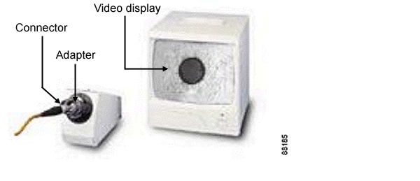
Video and Optical Fiberscopes

Fiberscopes are customized microscopes used to inspect optical fiber components. Figure 1-1 and Figure 1-2 show examples of available fiber scopes . The scope you chose should provide at least 200x magnification. Specific adapters are needed to properly inspect the ferrule faces of some connector types (such as the MPO, E2000, or MU connectors). In instances where multiple connector types need inspection, it may be more efficient to have a dedicated scope for each type of adapter.


Note To ensure personal eye safety, we strongly recommend that a video fiberscope be used for inspections. Be certain that optical fiberscopes have the appropriate wavelength band filters to protect the user.


Figure 1-1 Video Fiberscope—Desktop

Figure 1-2 Optical Fiberscopes—Handheld

Bulkhead Fiberscope

The bulkhead fiberscope is a handheld fiberscope used to inspect connectors in bulkhead ports. (See Figure 1-3.) The scope should provide at least 200x magnification displayed on a video monitor. Specific adapters are needed to properly inspect the ferrule faces of some connector types (such as the MPO, E2000, or MU connectors).

Figure 1-3 Bulkhead Fiberscope—Handheld

Laser Safety Glasses

Laser safety glasses can protect a person's eyes from laser light while handling fiber. They are intended to provide a level of protection across specific wavelengths. Be sure that the glasses are matched to the laser's wavelength. Laser safety glasses must meet federal and state regulations.

Cisco ONS 15540 ESPx Cleaning Kits

The Cisco ONS 15540 ESPx cleaning kit is available in two versions. The 2.5-Gbps transponder kit is used in systems with SM (single-mode), MM (multimode), and extended range transponder modules. Table 1-3 lists the contents of this kit. The 10-GE transponder kit is used in systems with the 10-GE transponder module. Table 1-4 lists the contents of this kit.
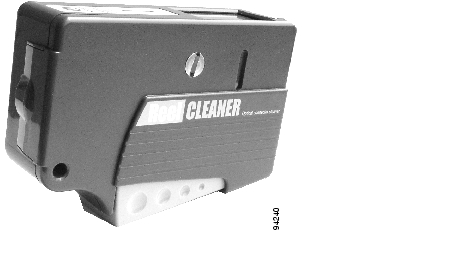
Table 1-3 2.5-Gbps Transponder Cleaning Kit Contents

Quantity
Part Number
Item Description

20

51-3507-01

Cleaning adapter for MU connector with cutout

5

51-3357-01

Cleaning adapter for MPO/MTP connector

1

74-3168-01

Cartridge cleaner (OPTIPOP) one slot

1

74-3167-01

Cartridge cleaner (OPTIPOP) for MPO/MTP with pins

1

51-3513-01

Package of 50 optical cleaning lint-free swabs (1.25 mm)

1

51-3359-01

Package of 250 optical cleaning lint-free swabs (2.5 mm)

1

800-22001-01

2.5-Gbps transponder cleaning module with dust caps


Table 1-4 10-GE Transponder Cleaning Kit Contents 

Quantity
Part Number
Item Description

20

51-3507-01

Cleaning adapter for MU connector with cutout

5

51-3357-01

Cleaning adapter for MPO/MTP connector

1

51-3613-01

Cartridge cleaner (OPTIPOP) one slot

1

51-3612-01

Cartridge cleaner (OPTIPOP) for MPO/MTP with pins

1

51-3513-01

Package of 50 optical cleaning lint-free swabs (1.25 mm)

1

51-3359-01

Package of 250 optical cleaning lint-free swabs (2.5 mm)

1

800-22481-01

10-Gbps transponder cleaning module with dust caps


Cartridge Cleaners

Cartridge cleaners contain a roll of woven material packaged in a cassette (see Figure 1-4). When a lever is pressed, a shutter opens to provide access to a fresh span of cleaning material. The following cartridges are included in the cleaning kit:

Cartridge cleaner (OPTIPOP) MPO/MTP with pins

Used to perform dry cleaning of MPO/MTP male connectors. It has two guide slots in the cleaning window. When the lever is pressed a shutter opens to provide a new section of the cleaning material.

Cartridge cleaner (OPTIPOP) with one slot

Used to perform dry cleaning of 2.5-mm (SC, FC, and so on) and 1.25-mm (MU, LC, and so on) ferrule connectors and female multi-fiber connectors such as MT-RJ. When the lever is pressed, a shutter opens to provide a new section of the cleaning material.


Note The ferrule is the part of the connector that keeps the fiber accurately aligned within the connector.


Figure 1-4 Cartridge Cleaner

Lint-Free Swabs

Swabs have a fabric tip at the end of a long stick. Lint-free swabs should be stored in a clean container to avoid contamination of the tip. Be sure to use a swab sized properly for the ferrule type (1.25 mm or 2.5 mm). See Figure 1-5.


Caution Never reuse a swab, it could transfer dirt or oils from one connector to another.

Figure 1-5 1.25-mm and 2.5-mm Lint-Free Swabs

Inspecting the Cisco ONS 15540 ESPx Fiber Optic Connections

Inspecting the fiber optic connectors for dust particles or other contaminants before bringing the card or module online can help to prevent system failures. Always work carefully around lasers and fiber optic connections. Keep the following information in mind.

Always turn off any laser sources before you inspect fiber connectors or optical components.

Always inspect the connectors or adapters before you clean.

Always inspect and clean the connectors before you make a connection.

Always use the connector housing to plug or unplug a fiber.

Always keep the protective cap on unplugged fiber connectors.

Always store unused protective caps in a resealable box and locate them near the connectors for easy access.

Always discard used lint-free swabs properly.

Always wear appropriate safety glasses when required in your production area.

Never look into a fiber while the system lasers are on.

Never use unfiltered handheld magnifiers or focusing optics to inspect fiber connectors.

Never connect a fiber to a fiberscope while the system lasers are on.

Never touch the end face of the fiber connectors.

Never twist or pull forcefully on the fiber cable.

Never reuse any lint-free swab or OPTIPOP cartridge cleaner reel.

Never touch the clean area of a lint-free swab or OPTIPOP cartridge cleaner.


Warning Invisible laser radiation may be emitted from the end of the unterminated fiber cable or connector. Do not view directly with optical instruments. Viewing the laser output with certain optical instruments (for example, eye loupes, magnifiers, and microscopes) within a distance of 100 mm may pose an eye hazard.


hometocprevnextglossaryfeedbacksearchhelp

Posted: Wed Jan 12 13:39:01 PST 2005
All contents are Copyright © 1992--2005 Cisco Systems, Inc. All rights reserved.
Important Notices and Privacy Statement.