|
|

Table Of Contents
Hardware Installation Procedures
NTP-2 Install the Cisco ONS 15540 ESPx Chassis
DLP-1 Flush-Mount the Cisco ONS 15540 ESPx
NTP-3 Install the Cable Management System
DLP-2 Install the Cable Management Tray
DLP-3 Install the Cable Management Drawer
DLP-4 Install Adapters in the Cross Connect Panel
DLP-5 Install the Vertical Cable Guide
NTP-4 Install Processor Cards, Line Card Motherboards, and Modules
DLP-6 Install the Processor Card
DLP-7 Install the Redundant Processor Card
DLP-8 Install the Mux/Demux Motherboard
DLP-9 Install the 4-Channel Mux/Demux Module
DLP-10 Install the 8-Channel Mux/Demux Module
DLP-11 Install the 32-Channel Terminal Mux/Demux Module
DLP-13 Install the 2.5-Gbps Line Card Motherboard
DLP-14 Install the 10-Gbps Line Card Motherboard
DLP-15 Install the Type 1 SM Transponder Module
DLP-16 Install the Type 1 MM Transponder Module
DLP-17 Install the 10-GE Transponder Module
DLP-18 Install the Type 2 Extended Range Transponder Module
DLP-20 Connect the Console Port
DLP-21 Connect the NME Port on the Processor Card
DLP-22 Connect the Auxiliary Port on the Processor Card
DLP-24 Clean Optical Connectors
DLP-25 Use Cable Storage Drawers
DLP-26 Connect the OSC to the Mux/Demux Module
DLP-27 Interconnect the Mux/Demux Modules
DLP-28 Connect the PSM to a Remote PSM
DLP-78 Connect the PSM to Transponder Modules
DLP-29 Connect the Transponder Modules to Client Equipment
DLP-30 Direct Connect the Mux/Demux Module to the 2.5-Gbps Line Card Motherboard
DLP-32 Direct Connect the Mux/Demux Module to the 10-Gbps Line Card Motherboard
DLP-33 Direct Connect the Mux/Demux Module to the 10-Gbps Line Card Motherboards Using Y Cables
DLP-35 Rack-Mount the 15540-PWR-AC External Power Shelf
DLP-36 Rack-Mount the 15540-ACPS-N-E External Power Shelf
DLP-37 Connect DC-Input Power from the 15540-ACPS-N-E External Power Shelf
DLP-38 Install the 15540-ACPS-N-E External Power Supply
DLP-39 Connect the 15540-ACPS-N-E External Power Supply
NTP-8 Verify Installation of Hardware
Hardware Installation Procedures
This chapter describes procedures for installing essential hardware components. This section describes common hardware installation and verification procedures and tasks. Refer to the Cisco ONS 15540 ESPx Hardware Installation Guide for complete hardware installation instructions.
Before You Begin
This section lists the chapter non-trouble procedures (NTPs). Turn to a procedure for applicable tasks or detailed level procedures (DLPs).
Step 1
2 Install the Cisco ONS 15540 ESPx Chassis—Complete this procedure to install the chassis in the rack.
Step 2
Step 3
Step 4
Step 5
Step 6
Step 7
NTP-2 Install the Cisco ONS 15540 ESPx Chassis
Step 1
Step 2
DLP-1 Flush-Mount the Cisco ONS 15540 ESPx
Warning
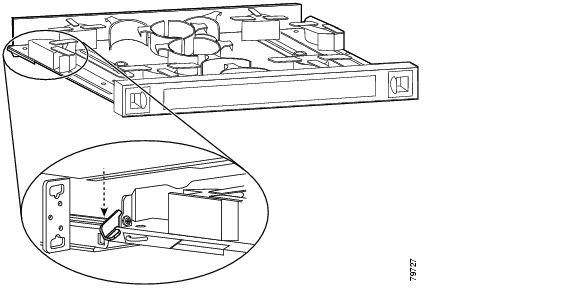
Step 1
Figure 2-1 Attaching Mounting Brackets to Shelf
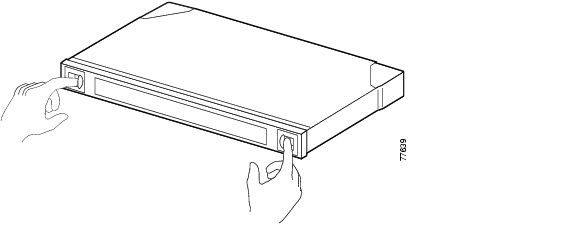
Step 2
Step 3
Figure 2-2 Attaching Shelf to Equipment Rack
Step 4
NTP-3 Install the Cable Management System
Step 1
Step 2
Step 3
Step 4
Step 5
DLP-2 Install the Cable Management Tray
Step 1
Step 2
Figure 2-3 Installing the Cable Management Tray
DLP-3 Install the Cable Management Drawer
Purpose
This task installs the cable management drawer.
Tools/Equipment
Number 1 Phillips screwdriver
Four 12-24 screwsPrerequisite Procedures
2 Install the Cisco ONS 15540 ESPx Chassis
Required/As Needed
Required
Onsite/Remote
Onsite
Security Level
None
Step 1
Figure 2-4 Installing the Fiber Routing Drawer
Step 2
Step 3
DLP-4 Install Adapters in the Cross Connect Panel
Purpose
This task installs the adapter in a cross connect drawer.
Tools/Equipment
Number 1 Phillips screwdriver
Four 12-24 screwsPrerequisite Procedures
2 Install the Cisco ONS 15540 ESPx Chassis
2 Install the Cable Management Tray
Required/As Needed
Required
Onsite/Remote
Onsite
Security Level
None
Step 1
Figure 2-5 Pulling out the Cross Connect Drawer
Step 2
Figure 2-6 Locking the Drawer
Step 3
Figure 2-7 Pulling up the Cross Connect Panel
Step 4
Step 5
Figure 2-8 Inserting the Adapter
Step 6
DLP-5 Install the Vertical Cable Guide
Purpose
This task installs the vertical cable guide to the rack.
Tools/Equipment
Number 1 Phillips screwdriver
Four 12-24 screwsPrerequisite Procedures
2 Install the Cisco ONS 15540 ESPx Chassis
2 Install the Cable Management Tray
Required/As Needed
As needed
Onsite/Remote
Onsite
Security Level
None
Step 1
Step 2
Figure 2-9 Placing the Vertical Cable Guides
Step 3
Step 4
Figure 2-10 Installing the Vertical Cable Guides
NTP-4 Install Processor Cards, Line Card Motherboards, and Modules
Step 1
Step 2
Step 3
Step 4
Step 5
Step 6
Step 7
Step 8
DLP-6 Install the Processor Card
Purpose
This task installs the processor card.
Tools/Equipment
Number 1 Phillips screwdriver
Prerequisite Procedures
Required/As Needed
Required
Onsite/Remote
Onsite
Security Level
None
Step 1
Step 2
Step 3
Note
Step 4
Table 2-1 Processor Card LEDs
STATUS
Red
A board resets or initially powers on.
Orange
System initialization.
Green
Full initialization and operational.
ACTIVE
Green
This board is the primary processor and is running IOS software.
STANDBY
Green
This board is the secondary processor.
SLOT 0
Green
Flash PC Card is present.
SLOT 1
Green
Flash PC Card is present.
NME1
FULL DUPLEX
Green
Full duplex is running.
Off
Half duplex is running.
100MBPS
Green
Operating at 100 Mbps.
Off
Operating at 10 Mbps.
LINK
Green
Link is up.
Off
Link is down.
ASE2
FULL DUPLEX
Green
Full duplex is running.
Off
Half duplex is running.
100MBPS
Green
Operating at 100 Mbps.
Off
Operating at 10 Mbps.
LINK
Green
Link is up.
Off
Link is down.
CRITICAL ALARM
Yellow
A critical alarm condition exists.
MAJOR ALARM
Yellow
A major alarm condition exists.
MINOR ALARM
Yellow
A minor alarm condition exists.
ALARM CUT OFF
Yellow
A major or minor alarm condition exists and the cutoff button has been pushed. Turns off by software when the original alarm clears or any new alarm occurs.
HIST
Yellow
A major or minor alarm occurred. Clears if the History Clear button is pushed and no alarm exists.
1 NME = network management Ethernet
2 ASE = aggregation shelf Ethernet
Step 5
DLP-7 Install the Redundant Processor Card
Purpose
This task installs the redundant processor card.
Tools/Equipment
Number 1 Phillips screwdriver
Prerequisite Procedures
Required/As Needed
As needed
Onsite/Remote
Onsite
Security Level
None
Step 1
Step 2
Step 3
Note
Step 4
DLP-8 Install the Mux/Demux Motherboard
Step 1
Step 2
Step 3
Caution
Step 4
Step 5
Step 6
Step 7
Note
Step 8
Note
DLP-9 Install the 4-Channel Mux/Demux Module
Step 1
Step 2
DLP-10 Install the 8-Channel Mux/Demux Module
Step 1
Step 2
DLP-11 Install the 32-Channel Terminal Mux/Demux Module
Step 1
Step 2
Step 3
Step 4
Step 5
Note
Step 6
DLP-12 Install the PSM
Purpose
This task installs the PSM (protection switch module) in a mux/demux motherboard.
Tools/Equipment
Number 1 Phillips screwdriver
Prerequisite Procedures
8 Install the Mux/Demux Motherboard, if needed
Required/As Needed
As needed
Onsite/Remote
Onsite
Security Level
None
Step 1
Step 2
Step 3
DLP-13 Install the 2.5-Gbps Line Card Motherboard
Step 1
Step 2
Caution
Step 3
Step 4
Step 5
Step 6
Step 7
Note
Step 8
DLP-14 Install the 10-Gbps Line Card Motherboard
Step 1
Step 2
Caution
Step 3
Step 4
Step 5
Step 6
Step 7
Note
Step 8
DLP-15 Install the Type 1 SM Transponder Module
Step 1
Step 2
Step 3
Step 4
Step 5
Note
Step 6
DLP-16 Install the Type 1 MM Transponder Module
Step 1
Step 2
Step 3
Step 4
Step 5
Note
Step 6
DLP-17 Install the 10-GE Transponder Module
Purpose
This task installs the 10-GE transponder module.
Tools/Equipment
Number 1 Phillips screwdriver
Prerequisite Procedures
Required/As Needed
As needed
Onsite/Remote
Onsite
Security Level
None
Step 1
Step 2
Step 3
Step 4
Step 5
Note
Step 6
DLP-18 Install the Type 2 Extended Range Transponder Module
Step 1
Step 2
Step 3
DLP-19 Install the SFP Optics
Purpose
This task installs the SFP optics.
Tools/Equipment
Number 1 Phillips screwdriver
Prerequisite Procedures
Required/As Needed
As needed
Onsite/Remote
Onsite
Security Level
None
Step 1
Note
Step 2
Step 3
NTP-5 Connect the Hardware
Purpose
This procedure describes to how connect the processor card ports and how to connect the optical fiber cables between the optical cards and modules.
Tools/Equipment
Straight-through EIA/TIA
Straight-through RJ-45
Auxiliary port cable
Optical cablesPrerequisite Procedures
2 Install the Cisco ONS 15540 ESPx Chassis
3 Install the Cable Management System
4 Install Processor Cards, Line Card Motherboards, and Modules
Required/As Needed
Required
Onsite/Remote
Onsite
Security Level
None
Step 1
Step 2
Step 3
Step 4
Step 5
Step 6
Step 7
Step 8
Step 9
Step 10
Step 11
Step 12
Step 13
Step 14
Step 15
DLP-20 Connect the Console Port
Purpose
This task connects the console port on the processor card.
Tools/Equipment
Straight-through EIA/TIA for the DB-25 console port
Prerequisite Procedures
7 Install the Redundant Processor Card, if redundancy is desired
Required/As Needed
Required for local console connection and for remote management connection
Onsite/Remote
Onsite
Security Level
None
Step 1
Step 2
Step 3
Step 4
DLP-21 Connect the NME Port on the Processor Card
Purpose
This task connects the NME (network management Ethernet) port on the processor card.
Tools/Equipment
Straight-through RJ-45 for the NME (network management Ethernet) port
Prerequisite Procedures
7 Install the Redundant Processor Card, if redundancy is desired
Required/As Needed
Required for10/100BASE-T network management LAN access.
Onsite/Remote
Onsite
Security Level
None
Step 1
Step 2
Step 3
Step 4
DLP-22 Connect the Auxiliary Port on the Processor Card
Purpose
This task connects the auxiliary port on the processor card.
Tools/Equipment
Aux port cable that ships with the shelf for the auxiliary port
Prerequisite Procedures
7 Install the Redundant Processor Card, if redundancy is desired
Required/As Needed
Required for modem access.
Onsite/Remote
Onsite
Security Level
None
Step 1
Step 2
Step 3
Step 4
DLP-23 Select Optical Cables
Purpose
This task selects the optical patch cables before you connect the hardware.
Tools/Equipment
None
Prerequisite Procedures
Required/As Needed
Required
Onsite/Remote
Onsite
Security Level
None
Step 1
Step 2
Step 3
Step 4
Step 5
DLP-24 Clean Optical Connectors
Step 1
Step 2
Step 3
The connectors used inside the system have been cleaned by the manufacturer and connected to the adapters in the proper manner. The operation of the system should be error free if the customer provides clean connectors on the application side, follows the previous directions, and ensures the following:
•
•
•
Note
DLP-25 Use Cable Storage Drawers
Purpose
This task describes how to use the cable storage drawers.
Tools/Equipment
None
Prerequisite Procedures
Required/As Needed
As needed
Onsite/Remote
Onsite
Security Level
None
Step 1
Figure 2-11 Opening the Cable Storage Drawer
Step 2
Figure 2-12 Pulling out the Cable Storage Drawer
Step 3
Figure 2-13 Locking the Drawer
Step 4
Step 5
Step 6
Step 7
Step 8
Step 9
DLP-26 Connect the OSC to the Mux/Demux Module
Purpose
This task connects the OSC to the mux/demux module.
Tools/Equipment
Two MU-to-MU cables per OSC module
Prerequisite Procedures
9 Install the 4-Channel Mux/Demux Module
10 Install the 8-Channel Mux/Demux Module
11 Install the 32-Channel Terminal Mux/Demux Module
Required/As Needed
As needed
Onsite/Remote
Onsite
Security Level
None
Step 1
Step 2
Step 3
Step 4
Figure 2-14 OSC Cabling
Step 5
DLP-27 Interconnect the Mux/Demux Modules
Purpose
This task interconnects the mux/demux modules by daisy chaining the cables.
Tools/Equipment
MU-to-MU connectors (short fiber length)
Prerequisite Procedures
9 Install the 4-Channel Mux/Demux Module or
10 Install the 8-Channel Mux/Demux Module or
11 Install the 32-Channel Terminal Mux/Demux Module.
Required/As Needed
As needed
Onsite/Remote
Onsite
Security Level
None
Step 1
Step 2
Step 3
Step 4
DLP-28 Connect the PSM to a Remote PSM
Step 1
Step 2
Step 3
Step 4
Step 5
Step 6
Figure 2-15 Cabling the PSM
DLP-78 Connect the PSM to Transponder Modules
Step 1
Step 2
Step 3
Note
Step 4
Step 5
Step 6
Step 7
Step 8
Figure 2-16 shows an example of cabling a PSM to a line card motherboard.
Figure 2-16 Cabling PSM to Line Card Motherboards
DLP-29 Connect the Transponder Modules to Client Equipment
Purpose
This task connects the transponder modules to the client equipment.
Tools/Equipment
MU-to-MU cables
Prerequisite Procedures
15 Install the Type 1 SM Transponder Module or
16 Install the Type 1 MM Transponder Module or
17 Install the 10-GE Transponder Module or
18 Install the Type 2 Extended Range Transponder Module
Required/As Needed
As needed
Onsite/Remote
Onsite
Security Level
None
Step 1
Step 2
Figure 2-17 Cabling Transponder Modules
Step 3
DLP-30 Direct Connect the Mux/Demux Module to the 2.5-Gbps Line Card Motherboard
Purpose
This task directly connects the mux/demux module to the line card motherboard using the cable storage drawer.
Tools/Equipment
MTP-to-MTP cable, blue
MTP cable installation toolPrerequisite Procedures
9 Install the 4-Channel Mux/Demux Module or
10 Install the 8-Channel Mux/Demux Module or
11 Install the 32-Channel Terminal Mux/Demux Module
13 Install the 2.5-Gbps Line Card Motherboard
Required/As Needed
As needed
Onsite/Remote
Onsite
Security Level
None
Step 1
Figure 2-18 Opening the Cable Storage Drawer
Step 2
Figure 2-19 Locking the Drawer
Step 3
Step 4
Step 5
Step 6
Step 7
Repeat Steps 1 through 4 to continue cabling the system without the cross connect panel.
Figure 2-20 Routing the MTP-to-MTP Cable
Step 8
Tip
DLP-31 Connect the Mux/Demux Module to the 2.5-Gbps Line Card Motherboard Using the Cross Connect Drawers
Purpose
This task connects the mux/demux module to the 2.5-Gbps line card motherboard using the cross connect drawer.
Tools/Equipment
MTP-to-8MU cable, gray
MTP-to-8MU cable, green
MU-to-MU cable
MTP cable installation toolPrerequisite Procedures
8 Install the Mux/Demux Motherboard
13 Install the 2.5-Gbps Line Card Motherboard
Required/As Needed
As needed
Onsite/Remote
Onsite
Security Level
None
Step 1
Figure 2-21 Opening the Cable Storage Drawer
Step 2
Step 3
Step 4
Step 5
Step 6
Step 7
Step 8
Figure 2-22 Pulling Up the Cross Connect Panel
Step 9
Figure 2-23 Routing the Cross Connect Cables
Step 10
Figure 2-24 Mounting the Transition Box
Step 11
Figure 2-25 Cross Connect Panel
Step 12
Step 13
Step 14
Step 15
Step 16
Tip
DLP-32 Direct Connect the Mux/Demux Module to the 10-Gbps Line Card Motherboard
Purpose
This task directly connects the mux/demux modules to the 10-Gbps line card motherboard using the cable storage drawer.
Tools/Equipment
Aqua MTP-to-MTP cable to connect lower channel 10-GE transponder module (channels 1/2, 5/6, 9/10, 13/14, 17/18, 21/22, 25/26, or 29/30)
Rose MTP-to-MTP cable to connect higher channel 10-GE transponder module (channels 3/4, 7/8, 11/12, 15/16, 19/20, 23/24, 27/28, or 31/32)
MTP cable installation tool
Prerequisite Procedures
8 Install the Mux/Demux Motherboard
9 Install the 4-Channel Mux/Demux Module
10 Install the 8-Channel Mux/Demux Module
11 Install the 32-Channel Terminal Mux/Demux Module
14 Install the 10-Gbps Line Card Motherboard
Required/As Needed
As needed
Onsite/Remote
Onsite
Security Level
None
Step 1
Figure 2-26 Opening the Cable Storage Drawer
Step 2
Figure 2-27 Locking the Drawer
Step 3
Note
Step 4
Step 5
Step 6
Step 7
Repeat Steps 1 through 4 to continue cabling the system without the cross connect panel.
Figure 2-28 Routing the MTP-to-MTP Cable
Step 8
Tip
DLP-33 Direct Connect the Mux/Demux Module to the 10-Gbps Line Card Motherboards Using Y Cables
Purpose
This task directly connects the mux/demux modules to the 10-Gbps line card motherboards using the y cable and the cable storage drawer.
Tools/Equipment
Blue MTP-to-2MTP cable
MTP cable installation toolPrerequisite Procedures
9 Install the 4-Channel Mux/Demux Module
10 Install the 8-Channel Mux/Demux Module
11 Install the 32-Channel Terminal Mux/Demux Module
Required/As Needed
As needed
Onsite/Remote
Onsite
Security Level
None
Step 1
Figure 2-29 Opening the Cable Storage Drawer
Step 2
Figure 2-30 Locking the Drawer
Step 3
Note
Step 4
Step 5
Step 6
Step 7
Step 8
Figure 2-31 Routing the MTP-to-2 MTP Cable
Step 9
Tip
DLP-34 Connect the Mux/Demux Module to the 10-Gbps Line Card Motherboard Using the Cross Connect Drawer
Purpose
This task connects the mux/demux modules to the 10-Gbps line card motherboards using the cross connect drawer.
Tools/Equipment
Aqua MTP-to-4 MU cables
Rose MTP-to-4 MU cables
MTP cable installation toolPrerequisite Procedures
14 Install the 10-Gbps Line Card Motherboard
17 Install the 10-GE Transponder Module
Required/As Needed
As needed
Onsite/Remote
Onsite
Security Level
None
Step 1
Figure 2-32 Opening the Cable Storage Drawer
Step 2
Step 3
Step 4
Step 5
Step 6
Step 7
Step 8
Figure 2-33 Pulling Up the Cross Connect Panel
Step 9
Figure 2-34 Routing the Cross Connect Cables
Step 10
Figure 2-35 Mounting the Transition Box
Step 11
Figure 2-36 Cross Connect Panel
Step 12
Step 13
Step 14
Step 15
Step 16
Tip
NTP-6 Ground the Shelf
Tip
Step 1
Step 2
Step 3
Step 4
Step 5
Note
Step 6
Step 7
Step 8
Step 9
Step 10
NTP-7 Power Up the Shelf
Step 1
Step 2
Step 3
Step 4
Step 5
Step 6
DLP-35 Rack-Mount the 15540-PWR-AC External Power Shelf
Purpose
This task installs the external power shelf.
Tools/Equipment
Number 1 Phillips screwdriver
Prerequisite Procedures
Required/As Needed
As needed
Onsite/Remote
Onsite
Security Level
None
Step 1
Note
Step 2
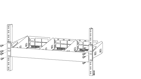
Step 3
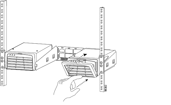
Figure 2-37 Installing the 15540-PWR-AC External Power Shelf in the Rack
Step 4
DLP-36 Rack-Mount the 15540-ACPS-N-E External Power Shelf
Purpose
This task installs the external power shelf.
Tools/Equipment
Number 1 Phillips screwdriver
Prerequisite Procedures
Required/As Needed
As needed
Onsite/Remote
Onsite
Security Level
None
Step 1
Note
Step 2
Step 3
Figure 2-38 Installing the 15540-ACPS-N-E External Power Shelf in the Rack
Step 4
Step 5
DLP-37 Connect DC-Input Power from the 15540-ACPS-N-E External Power Shelf
Purpose
This task connects the external power shelf.
Tools/Equipment
Number 1 Phillips screwdriver
Prerequisite Procedures
Required/As Needed
As needed
Onsite/Remote
Onsite
Security Level
None
Step 1
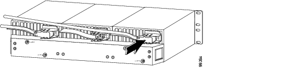
Figure 2-39 Installing the Cable Strain Relief Bracket
Step 2
Figure 2-40 Removing the Terminal Block Access Panel
Step 3
Step 4
•
•
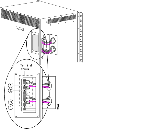
Note
Figure 2-41 Connecting Cable Wires to the Terminal Blocks
Step 5
•
•
Step 6
Step 7
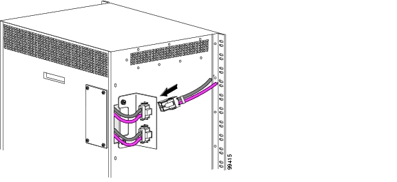
Figure 2-42 Installing the DC Power Cable
Step 8
Step 9
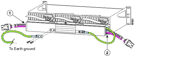
Figure 2-43 Connecting the DC Power Cables
DLP-38 Install the 15540-ACPS-N-E External Power Supply
Purpose
This task installs the external power supply.
Tools/Equipment
Number 1 Phillips screwdriver
Prerequisite Procedures
Required/As Needed
As needed
Onsite/Remote
Onsite
Security Level
None
Step 1
Figure 2-44 Opening the Release Handle
Step 2
Figure 2-45 Handling the 15540-ACPS-N-E Power Supply
Caution
Step 3
Figure 2-46 Installing the 15540-ACPS-N-E Power Supply
Step 4
Caution
DLP-39 Connect the 15540-ACPS-N-E External Power Supply
Purpose
This task connects the external power shelf.
Tools/Equipment
Power cord
Prerequisite Procedures
Required/As Needed
As needed
Onsite/Remote
Onsite
Security Level
None
Step 1
Figure 2-47 Installing the AC Power Cord
Step 2
•
•
Step 3
DLP-40 Verify the Powerup
Purpose
This task verifies the LEDs on the shelf after powerup.
Tools/Equipment
None
Prerequisite Procedures
37 Connect DC-Input Power from the 15540-ACPS-N-E External Power Shelf or
39 Connect the 15540-ACPS-N-E External Power SupplyRequired/As Needed
Required
Onsite/Remote
Onsite
Security Level
None
Step 1
Step 2
Step 3
Step 4
Step 5
Power-Supply ModulePower-Supply A is : OKPower-Supply B is : OKNTP-8 Verify Installation of Hardware
Purpose
This procedure verifies the hardware installation.
Tools/Equipment
Console
Prerequisite Procedures
2 Install the Cisco ONS 15540 ESPx Chassis
3 Install the Cable Management System
4 Install Processor Cards, Line Card Motherboards, and Modules
Required/As Needed
Required
Onsite/Remote
Onsite
Security Level
None
Step 1
The CLI (command-line interface) on the console prompts you to enter the initial configuration dialog. Answer no to this prompt as follows:
Would you like to enter the initial dialog? [yes]:no
Note
Step 2
Switch>enable
Switch#Step 3
Switch# show hardware------------------------------------------------------------------------------CN_Tower_Backplane named Switch, Date: 12:44:21 UTC Fri Nov 14 2003------------------------------------------------------------------------------------------------------------------------------------------------------------Back-Plane Information------------------------------------------------------------------------------Orderable Product No. MAC-Address MAC-Size Serial No. Mfg. Date H/W V--------------------- ----------------- -------- ------------ ---------- -----15540-CHSA 00-00-16-44-3e-b7 16 TBC04501952 01/09/2002 3.0------------------------------------------------------------------------------Slot Orderable Product No. Part No. Rev Serial No. Mfg. Date H/W Ver.---- ------------------------- ---------- --- ------------ ---------- --------0/* 15540-LCMB-UNKNOWN 73-7793-02 11 CAB0604MD7A 2/20/2002 1.00/2 15540-MDXC-16EH= 74-2858-01 01 ANX0614000N 06/18/2002 1.01/* 15540-LCMB-UNKNOWN 73-7793-01 11 CAB0604MD7R 01/29/2002 1.01/0 15440-MDXD-16AD= 74-2857-01 A1 404049 03/04/2002 1.01/2 0 403416 01/18/2002 0.13/* 15540-TBD 73-7789-01 03 CAB0543L2SX 11/5/2001 5.03/0 N/A 68-1105-02 02 CAB0513HGV6 02/23/2001 2.323/1 N/A 68-1105-02 02 CAB0512HGPA 02/23/2001 2.323/2 15540-TSP2-0300= 68-1342-06 A1 CNH0716004N 04/22/2003 5.13/3 15540-TSP2-0300= 68-1342-06 A1 CNH0716003V 04/22/2003 5.14/* 15540-TBD 73-7789-03 A0 CAB0605MF0P 02/06/2002 2.34/0 15540-MDXE-0203 05-1197-01 C^NΠ DIF07420102 01/01/2000 1.04/1 15540-MDXE-OSC 05-1211-01 C^NΠ DIF07430109 10/22/2003 1.04/2 15540-MDXE-0204 05-1198-01 C^NΠ DIF07430108 10/22/2003 1.04/3 15540-04 05-1194-01 C^NΠ DIF07400104 01/01/2000 1.06/* 15540-CPU= 73-5621-06 A1 CAB0553M51D 01/11/2002 6.27/* N/A 73-5621-02 02 CAB0505GZH3 02/15/2001 2.58/* 15540-LCMB-1100= 68-1672-03 A0 CAB06310XYA 09/23/2002 2.28/0 15540-MDXE-OSC 05-1211-01 C^NΠ DIF07430110 10/22/2003 1.08/1 15540-MDXE-0201 05-1195-01 C^NΠ DIF07430107 10/22/2003 1.08/2 15540-MDXE-0201 05-1195-01 C^NΠ DIF07420107 01/01/2000 1.08/3 15540-04 05-1194-01 C^NΠ DIF07410105 01/01/2000 1.0------------------------------------------------------------------------------Power-Supply Module------------------------------------------------------------------------------Power-Supply A is : OKPower-Supply B is : Not workingESPx-ALPHA#Step 4
Switch# show hardware detail--------------------------------------------------------------------------------------------------------------------------------------------------------------Back-Plane Information-------------------------------------------------------------------------------Orderable Product No. MAC-Address MAC-Size Serial No. Mfg. Date H/W Ve--------------------- ----------------- -------- ------------ ---------- ------15540-CHSA 00-00-16-44-3e-b7 16 TBC04501952 01/09/2002 3.0-------------------------------------------------------------------------------Slot Orderable Product No. Part No. Rev Serial No. Mfg. Date H/W Ver.---- ------------------------- ---------- --- ------------ ---------- ---------0/* 15540-LCMB-UNKNOWN 73-7793-02 11 CAB0604MD7A 2/20/2002 1.00/2 15540-MDXC-16EH= 74-2858-01 01 ANX0614000N 06/18/2002 1.01/* 15540-LCMB-UNKNOWN 73-7793-01 11 CAB0604MD7R 01/29/2002 1.01/0 15440-MDXD-16AD= 74-2857-01 A1 404049 03/04/2002 1.01/2 0 403416 01/18/2002 0.13/* 15540-TBD 73-7789-01 03 CAB0543L2SX 11/5/2001 5.03/0 N/A 68-1105-02 02 CAB0513HGV6 02/23/2001 2.323/1 N/A 68-1105-02 02 CAB0512HGPA 02/23/2001 2.323/2 15540-TSP2-0300= 68-1342-06 A1 CNH0716004N 04/22/2003 5.13/3 15540-TSP2-0300= 68-1342-06 A1 CNH0716003V 04/22/2003 5.14/* 15540-TBD 73-7789-03 A0 CAB0605MF0P 02/06/2002 2.34/0 15540-MDXE-0203 05-1197-01 C^NΠ DIF07420102 01/01/2000 1.04/1 15540-MDXE-OSC 05-1211-01 C^NΠ DIF07430109 10/22/2003 1.04/2 15540-MDXE-0204 05-1198-01 C^NΠ DIF07430108 10/22/2003 1.04/3 15540-04 05-1194-01 C^NΠ DIF07400104 01/01/2000 1.06/* 15540-CPU= 73-5621-06 A1 CAB0553M51D 01/11/2002 6.27/* N/A 73-5621-02 02 CAB0505GZH3 02/15/2001 2.58/* 15540-LCMB-1100= 68-1672-03 A0 CAB06310XYA 09/23/2002 2.28/0 15540-MDXE-OSC 05-1211-01 C^NΠ DIF07430110 10/22/2003 1.08/1 15540-MDXE-0201 05-1195-01 C^NΠ DIF07430107 10/22/2003 1.08/2 15540-MDXE-0201 05-1195-01 C^NΠ DIF07420107 01/01/2000 1.08/3 15540-04 05-1194-01 C^NΠ DIF07410105 01/01/2000 1.0-------------------------------------------------------------------------------Power-Supply Module-------------------------------------------------------------------------------Power-Supply A is : OKPower-Supply B is : Not workingESPx-ALPHA#sh hardware detail-------------------------------------------------------------------------------CN_Tower_Backplane named Switch, Date: 12:47:08 UTC Fri Nov 14 2003--------------------------------------------------------------------------------------------------------------------------------------------------------------Back-Plane Information-------------------------------------------------------------------------------Slot Number : N/AController Type : 0x1006On-Board Description : CN_Tower_BackplaneOrderable Product Number: 15540-CHSABoard Part Number : 73-5655-03Board Revision : 02Serial Number : TBC04501952Manufacturing Date : 01/09/2002Hardware Version : 3.0RMA Number : 0x00RMA Failure Code : 0x00Optical Back-Plane Type : Patchable Optical BackplaneMAC Address: 00-00-16-44-3e-b7MAC Address Block Size : 16-------------------------------------------------------------------------------Slot Number : 0/*Controller Type : 0x101AOn-Board Description : CN_TOWER_MUX/DEMUX_OSCOrderable Product Number: 15540-LCMB-UNKNOWNBoard Part Number : 73-7793-02Board Revision : 11Serial Number : CAB0604MD7AManufacturing Date : 2/20/2002Hardware Version : 1.0RMA Number : 0x00RMA Failure Code : 0x00Functional Image Version: 2.67Function-ID : 0-------------------------------------------------------------------------------Slot Number : 0/2Controller Type : 0x1025On-Board Description : Mux_16ChannelOrderable Product Number: 15540-MDXC-16EH=Board Part Number : 74-2858-01Board Revision : 01Serial Number : ANX0614000NManufacturing Date : 06/18/2002Hardware Version : 1.0RMA Number :RMA Failure Code :-------------------------------------------------------------------------------Slot Number : 1/*Controller Type : 0x101AOn-Board Description : CN_TOWER_MUX/DEMUX_OSCOrderable Product Number: 15540-LCMB-UNKNOWNBoard Part Number : 73-7793-01Board Revision : 11Serial Number : CAB0604MD7RManufacturing Date : 01/29/2002Hardware Version : 1.0RMA Number : 0x00RMA Failure Code : 0x00Functional Image Version: 2.67Function-ID : 0-------------------------------------------------------------------------------
![]()
![]()
![]()
![]()
![]()
![]()
![]()
![]()
Posted: Wed Jan 12 14:10:25 PST 2005
All contents are Copyright © 1992--2005 Cisco Systems, Inc. All rights reserved.
Important Notices and Privacy Statement.