|
|

Product Numbers:
MEM-C5K-128M-UPGD= Route Switch Feature Card 128-MB Upgrade Kit
This configuration note contains procedures for installing the 128-MB single inline memory module (SIMM) upgrade kit for the Catalyst 5000 family Route Switch Feature Card (RSFC). The RSFC is an optional enhancement for the Supervisor Engine II G and III G.
This document contains the following sections:
 |
Note Before you install, operate, or service the system, read the Site Preparation and Safety Guide. This guide contains important safety information you should know before working with the system. |
The following tools are required to remove and replace the SIMM:
|
Note Refer to the installation guide for your switch for ESD details including the locations of the ESD connectors on the Catalyst 5000 family switches. |
To upgrade the RSFC SIMMs, you must remove the supervisor engine from the switch and detach the RSFC from the supervisor engine motherboard. Perform the procedures in the following sections in the order provided to upgrade the RSFC SIMMs:
|
Note Catalyst 5505, Catalyst 5509, and Catalyst 5500 switches---When two supervisor engines are installed, hot swapping allows you to remove and replace one of the supervisor engines without turning off the system power. |
The ejector levers on the supervisor engine align and seat the supervisor engine connectors in the backplane. See Figure 1. If you fail to use the ejector levers to insert the supervisor engine, you can disrupt the order in which the pins make contact with the backplane. When removing a supervisor engine, use the ejector levers to ensure that the supervisor engine connector pins disconnect from the backplane properly. Any supervisor engine that is only partially connected to the backplane can disrupt the system.
Before you remove the supervisor engine from the switch, you should first upload the current configuration to a server. This saves time when bringing the supervisor engine back online. Enter the write network command to upload the configuration file to the network. Enter the copy command to download the current configuration to a Flash memory device on the new supervisor engine.
 |
Caution To prevent ESD damage, handle switching modules by the carrier edges only. |
|
Caution When removing or inserting a switching module, always wear an ESD wrist strap connected to the Catalyst 5000 family switch ESD wrist strap connector. |
To remove the supervisor engine from the switch, follow these steps:
Step 2 Grasp the left and right ejector levers. Simultaneously pull the left lever to the left and the right lever to the right to release the supervisor engine from the backplane connector.
Step 3 Grasp the supervisor engine with one hand and place your other hand under the carrier to support and guide the supervisor engine out of the slot. Avoid touching any of the components on the supervisor engine.
Step 4 Carefully pull the supervisor engine straight out of the slot, keeping your other hand under the carrier to guide it. Keep the supervisor engine horizontal to the backplane.
Step 5 Place the removed supervisor engine on an antistatic mat, foam, or bag.
|
Note When you remove and replace the supervisor engine, the system provides status messages on the console screen. The messages are for information only. Enter the show system and show module commands to view specific information. For additional information, refer to the Software Configuration Guide and Command Reference for your switch. |
The SIMM slots are located on the underside of the RSFC motherboard. To install the SIMMs, you must first remove the RSFC.
|
Caution Always use an ESD wrist strap when handling modules or coming into contact with internal components. |
To remove the RSFC from the supervisor engine, follow this procedure:

Step 2 Gently remove the RSFC from the supervisor engine.
Step 3 Turn the RSFC over from right to left as shown in Figure 3 and gently place it on an antistatic mat or bag.

The SIMM slots are located on the underside of the RSFC. See Figure 4 for the location of the SIMM slots.

|
Caution Handle SIMMs by their edges only; avoid touching the memory module, pins, or traces (the metal fingers along the connector edge of a SIMM). SIMMs are sensitive components that are susceptible to ESD damage and can be damaged by mishandling. |
To remove the installed SIMMs and replace them with the 128-MB SIMM upgrade set, see Figure 5 and perform the following procedure:
Step 2 Hold each SIMM by its edges and gently lift and remove them, placing them on an antistatic mat or foam.
Step 3 Remove the replacement 128-MB SIMM set from its package, holding each SIMM by its edges, and carefully insert them, one at a time, into each connector so that they click into place. Make sure the polarity notch is pointed to the right side of each SIMM clip.

This section describes how to install the RSFC in your Supervisor Engine II G or III G.
To install the RSFC in the supervisor engine, follow this procedure:
Step 2 Ensure that the RSFC is securely seated in the supervisor engine.
Step 3 Use a Phillips-head screwdriver to tighten the eight screws that secure the RSFC to the supervisor engine standoffs.
When installing the supervisor engine, note that it must go in a specific slot:
|
Caution To prevent ESD damage, handle switching modules by the carrier edges only. |
|
Caution When removing or inserting a switching module, always wear an ESD wrist strap connected to the Catalyst 5000 family switch ESD wrist strap connector. |
To install the supervisor engine, follow these steps:
Step 2 Align the edges of the supervisor engine carrier with the slot guides on the sides of the switch chassis.
Step 3 Pivot the two module ejector levers out away from the faceplate. The ejector levers are shown pivoted out in Figure 6.

Step 4 Keeping one hand under the carrier to guide the supervisor engine, carefully slide it into the slot on the switch until the ejector levers click into place on the chassis.
Be sure to keep the module horizontal to the backplane and avoid touching any of the components on the module.
Step 5 Using the thumb and forefinger of each hand, simultaneously pivot in both ejector levers, as shown in Figure 6, to fully seat the switching module in the backplane connector.
|
Caution Always use the ejector levers when installing or removing switching modules. A module that is partially seated in the backplane will cause the system to halt and subsequently crash. |
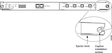
Step 6 Use a screwdriver to tighten the captive installation screws at the left and right sides of the module.
Catalyst 5000 family modules, when intalled in a system, comply with the standards listed in Table 1:
| Specification | Description | |
Compliance | CE1 Marking |
|
Safety | UL2 1950, CSA3-C22.2 No. 950, EN460950, IEC5 950, TS6 001, AS/NZS7 3260 | |
EMI8 | FCC9 Class A (47 CFR10, Part 15), ICES11-003 Class A, EN55022 Class A, CISPR22 Class A, AS/NZS 3548 Class A, and VCCI12 Class A with UTP13 | |
This equipment has been tested and found to comply with the limits for a Class A digital device, pursuant to part 15 of the FCC rules. These limits are designed to provide reasonable protection against harmful interference when the equipment is operated in a commercial environment. This equipment generates, uses, and can radiate radio-frequency energy and, if not installed and used in accordance with the instruction manual, may cause harmful interference to radio communications. Operation of this equipment in a residential area is likely to cause harmful interference, in which case users will be required to correct the interference at their own expense.
You can determine whether your equipment is causing interference by turning it off. If the interference stops, it was probably caused by the Cisco equipment or one of its peripheral devices. If the equipment causes interference to radio or television reception, try to correct the interference by using one or more of the following measures:
Modifications to this product not authorized by Cisco Systems could void the FCC approval and negate your authority to operate this product.
For more detailed installation and configuration information, refer to the following publications:
Cisco Connection Online (CCO) is Cisco Systems' primary, real-time support channel. Maintenance customers and partners can self-register on CCO to obtain additional information and services.
Available 24 hours a day, 7 days a week, CCO provides a wealth of standard and value-added services to Cisco's customers and business partners. CCO services include product information, product documentation, software updates, release notes, technical tips, the Bug Navigator, configuration notes, brochures, descriptions of service offerings, and download access to public and authorized files.
CCO serves a wide variety of users through two interfaces that are updated and enhanced simultaneously: a character-based version and a multimedia version that resides on the World Wide Web (WWW). The character-based CCO supports Zmodem, Kermit, Xmodem, FTP, and Internet e-mail, and it is excellent for quick access to information over lower bandwidths. The WWW version of CCO provides richly formatted documents with photographs, figures, graphics, and video, as well as hyperlinks to related information.
You can access CCO in the following ways:
For a copy of CCO's Frequently Asked Questions (FAQ), contact cco-help@cisco.com. For additional information, contact cco-team@cisco.com.
|
Note If you are a network administrator and need personal technical assistance with a Cisco product that is under warranty or covered by a maintenance contract, contact Cisco's Technical Assistance Center (TAC) at 800 553-2447, 408 526-7209, or tac@cisco.com. To obtain general information about Cisco Systems, Cisco products, or upgrades, contact 800 553-6387, 408 526-7208, or cs-rep@cisco.com. |
Cisco documentation and additional literature are available in a CD-ROM package, which ships with your product. The Documentation CD-ROM, a member of the Cisco Connection Family, is updated monthly. Therefore, it might be more current than printed documentation. To order additional copies of the Documentation CD-ROM, contact your local sales representative or call customer service. The CD-ROM package is available as a single package or as an annual subscription. You can also access Cisco documentation on the World Wide Web at http://www.cisco.com, http://www-china.cisco.com, or http://www-europe.cisco.com.

![]()
![]()
![]()
![]()
![]()
![]()
![]()
![]()
Posted: Thu Jan 20 16:51:05 PST 2000
Copyright 1989 - 2000©Cisco Systems Inc.