|
|

This chapter provides safety information, instructions for checking the contents of the Cisco 6400 carrier-class broadband aggregator shipping container, and directions for unpacking and repacking the Cisco 6400.
This chapter includes the following:
 |
Note The illustrations in this guide depict the original Cisco 6400 chassis. Your chassis may appear or look slightly different. |
Completing these steps will help you prepare for the installation of the Cisco 6400.
Step 2 Unpack and check the contents of the shipping container against the unpacking instructions attached to the outside of the shipping container. Refer to the section "Unpacking and Repacking the System."
Step 3 Check that you have received all the system components you need to install the Cisco 6400. Refer to the section "Checking System Components Prior to Installation."
Step 4 If you have to return or move the system to a different site, refer to the section "Unpacking and Repacking the System."
"Configuration Worksheets" contains forms to be used during the initial installation and subsequent maintenance of your Cisco 6400. Copy the configuration worksheets and use them to record installation and configuration information. Retain these worksheets along with other records as part of the Site Log (also in "Configuration Worksheets").
When installing the Cisco 6400, observe all caution and warning statements. For warning translations, refer to the Regulatory Compliance and Safety Information for the Cisco 6400 (Cisco document number 78-5789-xx).
The following guidelines will help ensure your safety and protect the equipment. However, these guidelines may not cover all potentially hazardous situations you may encounter during system installation.
 |
Warning Only trained and qualified personnel should be allowed to install or replace this equipment. To see translations of this warning, refer to the Regulatory Compliance and Safety Information document that accompanied this device. |
|
Warning This unit is intended for installation in restricted access areas. A restricted access area is where access can only be gained by service personnel through the use of a special tool, lock and key, or other means of security, and is controlled by the authority responsible for the location. To see translations of this warning, refer to the Regulatory Compliance and Safety Information document that accompanied this device. |
|
Warning This equipment is to be installed and maintained by service personnel only as defined by AS/NZS 3260 Clause 1.2.14.4 Service Personnel. To see translations of this warning, refer to the Regulatory Compliance and Safety Information document that accompanied this device. |
|
Warning Before working on a chassis or working near power supplies, unplug the power cord on AC units; disconnect the power at the circuit breaker on DC units. To see translations of this warning, refer to the Regulatory Compliance and Safety Information document that accompanied this device. |
|
Warning Do not touch the power supply when the power cord is connected. For systems with a power switch, line voltages are present within the power supply even when the power switch is off and the power cord is connected. For systems without a power switch, line voltages are present within the power supply when the power cord is connected. To see translations of this warning, refer to the Regulatory Compliance and Safety Information document that accompanied this device. |
The fully configured system weighs approximately 130 pounds. The chassis is not intended to be moved frequently. Before you install the system, ensure that your site is properly prepared so you can avoid having to move the chassis later to accommodate power sources and network connections. For more information about site preparation, refer to the Cisco 6400 Site Planning Guide.
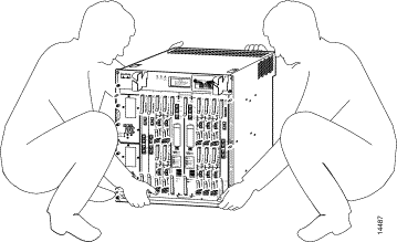
Two or more people are required to lift the chassis. Whenever you lift the chassis or any heavy object, follow these guidelines:
|
Warning To prevent personal injury or damage to the chassis, never attempt to lift or tilt the chassis using the handles on modules (such as power supplies, fans or cards); these types of handles are not designed to support the weight of the unit. Lift the unit only by using handles that are an integral part of the chassis, or by grasping the chassis underneath its lower edge. To see translations of this warning, refer to the Regulatory Compliance and Safety Information document that accompanied this device. |
|
Warning Two people are required to lift the chassis. To prevent injury, keep your back straight and lift with your legs, not your back. To see translations of this warning, refer to the Regulatory Compliance and Safety Information document that accompanied this device. |
To safely lift the chassis:
Step 2 With the other hand, grasp the top rear of the chassis under the air exhaust and carefully lift the chassis as shown in Figure 2-1.
All system components are redundant. They are designed to be removed and replaced while the system is operating without presenting an electrical hazard or damage to the system.
Follow these basic guidelines when you are working with any electrical equipment:
In addition, use the guidelines that follow when working with any equipment that is disconnected from a power source but is still connected to telephone wiring or other network cabling.
|
Warning Do not work on the system or connect or disconnect cables during periods of lightning activity. To see translations of this warning, refer to the Regulatory Compliance and Safety Information document that accompanied this device. |
|
Warning Read the installation instructions before you connect the system to its power source. To see translations of this warning, refer to the Regulatory Compliance and Safety Information document that accompanied this device. |
Electrostatic discharge (ESD) damage, which occurs when electronic cards or components are improperly handled, can result in complete or intermittent failures. The node switch processor (NSP), node route processor (NRP), and node line card (NLC) each consist of a printed circuit card that is fixed in a metal carrier. Electromagnetic interference (EMI) shielding and connectors are integral components of the carrier. Although the metal carrier helps to protect the cards from ESD, use an antistatic strap whenever you handle the modules. Handle the carriers by the edges only; never touch the cards or connector pins.
 |
Caution Always tighten the captive installation screws on all system components when you are installing them. These screws prevent accidental removal of the module, provide proper grounding for the system, and help to ensure that the bus connectors are properly seated in the backplane. |
Following are guidelines for preventing ESD damage:
|
Caution For safety, periodically check the resistance value of the antistatic strap. The measurement should be between 1 and 10 megohms. |

The Cisco 6400 is shipped assembled in a cardboard box. Power cables, manuals, and other additional items are packaged in separate boxes.
Unpacking instructions are attached to the outside of the shipping container. To verify that you have received all of the required components, see the "Checking the Contents" section.
|
Caution Static voltages as low as 30 volts can damage circuitry. Be sure to observe all standard anti-static procedures (for example, wear a grounding strap) when handling electronic equipment and components. |
To unpack the Cisco 6400:
Step 2 Remove strapping tape (Figure 2-3) and any exterior covering from the pallet, and place the accessory boxes on a flat, solid surface where they can be unpacked separately.

|
Note Do not discard the shipping containers after you have unpacked the system. Flatten the shipping cartons and store them with the pallet. You will need these containers if you want to move or ship the system in the future. |
Step 3 Review chassis lifting guidelines in the section "Safely Lifting the Chassis" section.
Step 4 Carefully remove the system chassis from its container.
Step 5 Open the boxes that contain the cables and documentation. (Do not use a knife to open these boxes.) Carefully inspect the items for damage.
Use the worksheets in "Configuration Worksheets" while checking the contents of the shipping container. The completed System Installation Checklist provides a record of components that you have ordered and received.
To verify the contents of the Cisco 6400 shipping container:
Step 2 Check that all line cards are included in the shipment. Ensure that the configuration matches the packing list and that all of the interfaces are included.
Step 3 Complete the Port Configuration Worksheet in "Configuration Worksheets."
If your system is damaged, you will need to repack it for return shipment. Use the original shipping containers. Figure 2-4 shows an exploded view of the system and packing materials.
To return or move the Cisco 6400 to a different location, follow these instructions for repacking the system, using the original packaging material:
Step 2 Use at least two people to place the Cisco 6400 chassis inside the container. Be sure that the chassis is positioned correctly before you lower it inside the container.
Step 3 Place the top packing material over the top of the Cisco 6400 chassis.
Step 4 Place both accessory boxes inside the cutouts in the top section of the packing material.
Step 5 Fold the outside carton down over the top of the accessory boxes and seal with packing tape. Figure 2-3 shows the packaged Cisco 6400.
Step 6 Wrap two packaging straps tightly around the top and bottom of the package to hold the outside carton and the bottom pallet.
|
Note Do not use tape to hold the outside carton to the bottom pallet. You must use packaging straps. |

Before beginning installation of your Cisco 6400, you should verify that you have received all hardware and documentation items listed on the shipping receipt or the bill of materials (BOM). Record information about your Cisco 6400 using the worksheets in "Configuration Worksheets." You should also verify that you have all of the cables, connectors, and adapters required for your particular location.
![]()
![]()
![]()
![]()
![]()
![]()
![]()
![]()
Posted: Fri Jul 5 10:53:21 PDT 2002
All contents are Copyright © 1992--2002 Cisco Systems, Inc. All rights reserved.
Important Notices and Privacy Statement.