|
|

Table Of Contents
Rack-Mounting the Cisco uBR 3x10 RF Switch with the Cisco uBR10012 CMTS
Cables Used with These Configurations
Attaching the Cable Management Bracket
Quick Start Guide
Rack-Mounting the Cisco uBR 3x10 RF Switch with the Cisco uBR10012 CMTS
Warning
Only trained and qualified personnel should be allowed to install, replace, or service this equipment. Statement 1030
1 Overview
This quick start guide provides basic instructions for rack-mounting a Cisco uBR 3x10 RF Switch in a 4-post equipment rack with the CiscouBR0012 CMTS.
Before proceeding with the installation, review the safety information in the Cisco RF Switch Regulatory Compliance and Safety Information.
Tip
Sample Configurations
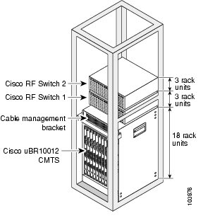
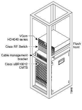
The following illustrations show sample configurations using the Cisco uBR3x10 RF Switch in a Cisco uBR10012 CMTS.
Figure 1 Cisco RF Switches Installed in a Cisco uBR10012 CMTS Using Cisco uBR10-MC5x20S/U Line Cards
Figure 2 Cisco RF Switch Installed in a Cisco uBR10012 CMTS Using Cisco uBR10-LCP2-MC28C Line Cards
2 Required Equipment
The following equipment is required for rack-mounting the Cisco uBR 3x10 RF Switch in a standard 19-inch-wide 4-post equipment rack.
Note
Tools and Equipment
•
•
•
•
•
•
•
•
•
•
•
Cables Used with These Configurations
•
MCX to MCX connector•
MCX to MCX connector•
MCX to F connector•
MCX to F connectors
Tip
3 Attaching the Brackets
Step1
Step2
Step3
Step4
Step5
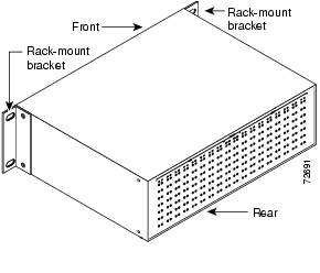
Figure 3 Front-Mounted Brackets
4 Rack-Mounting the Switch
Caution
Step1
Step2
Step3
Step4
Note
Step5
Tip
Step6
5 Grounding the Chassis
Caution
Step1
Step2
Step3
Step4
Step5
Figure 4 Grounding Lug Location
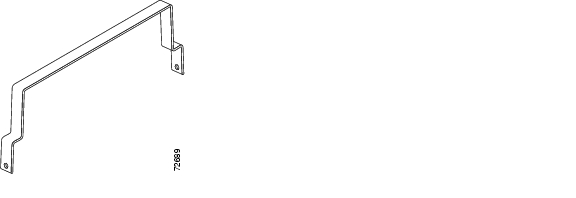
Attaching the Cable Management Bracket
A cable management bracket is included in the shipping container. We recommend using this bracket to ensure proper airflow in the chassis.
Step1
Step2
Step3
Step4
Figure 5 Cable-Management Bracket
6 Technical Specifications
7 Related Documentation
•
http://www.cisco.com/en/US/products/hw/
cable/ps2929/prod_installation_guides
_list.html•
http://www.cisco.com/en/US/products/hw/
cable/ps2929/products_quick_start_list.html•
•
http://www.cisco.com/univercd/cc/td/doc/
es_inpck/cetrans.htm•
http://www.vcom.com
![]()
![]()
![]()
![]()
![]()
![]()
![]()
![]()
Posted: Fri Mar 12 08:37:14 PST 2004
All contents are Copyright © 1992--2004 Cisco Systems, Inc. All rights reserved.
Important Notices and Privacy Statement.