|
|

Table Of Contents
Cabling the Cisco uBR 3x10 RF Switch to the Cisco uBR10012 CMTS
Connecting RF Cables to the Cisco uBR 3x10 RF Switch
Connecting the RF Cables to the Header Blocks
Quick Start Guide
Cabling the Cisco uBR 3x10 RF Switch to the Cisco uBR10012 CMTS
Warning
Only trained and qualified personnel should be allowed to install, replace, or service this product. Statement 1030.
Caution
1 Overview
This quick start guide describes the equipment and steps used to connect coaxial cables between the Cisco 3x10 RF Switch and the working and protect cable interface line cards (Cisco uBR-MC28C, and Cisco uBR-MC16C, E, or S) in a Cisco uBR10012 Cable Modem Termination System (CMTS).
A single Cisco uBR10012 CMTS supports up to eight Cisco cable interface line cards. Each line card has one or two downstream and six or eight upstream cable interfaces for a total of up to 16 downstream and 64 upstream interfaces in a fully populated chassis.
2 Protection Scheme
The N+1 redundancy protection scheme you select for your system depends on the number of cable interface line cards you have installed in the Cisco uBR10012 CMTS. The 7+1 eight-card redundancy scheme supports redundancy for the cable interface line cards installed in a fully populated Cisco uBR10012 chassis.
One Cisco 3x10 RF Switch is used in this configuration, allowing you to deploy a redundancy scheme where one protecting cable interface line card supports from one to seven working cable interface line cards in the same chassis.
3 RF Cable Assemblies
The following sections describe the coaxial cable, F-connector assemblies, and header blocks required to support N+1 redundancy using the Cisco uBR 3x10 RF Switch, Cisco CMTSs, and the Vecima HD4040 series IF-to-RF upconverter.
Although you may construct and implement your own cabling system according to the specifications outlined here, we recommend using the Cisco N+1 cabling solution designed specifically for this CMTS feature and the Cisco pre-assembled, terminated cables and cable bundles.
•
•
Coaxial Cables
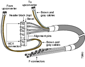
The coaxial cable approved for use in the Cisco N+1 cable assembly is Belden YR46940. The cable bundle features 10 individual segments of Belden YR46940-type coaxial cable enclosed in an external sheath. Each segment of coaxial cable is a different color. The single gray and brown RF cables are pre-terminated with F-connectors to accommodate downstream IF signals from the Cisco CMTS to the Vecima HD4040 series IF-to-RF upconverter input. (See Figure 1.)
Figure 1 Cable Bundle and Header Block
Tip
Connectors
The MCX connectors that terminate in the header block at the Cisco RF Switch are a special 75-ohm MCX connector available from White Sands Engineering.
The F-connectors that terminate at the upconverter are Whitesands ASFP connectors (or alternate). The output cabling kit includes 13 F-connectors to use for modification or repair.
Header Blocks
The header block holds the MCX connectors that terminate the coaxial cables. These are Cisco MCX header blocks that mate to the Cisco 3x10 RF Switch. (See Figure 1.)
The header blocks are slightly beveled at the top and have offset alignment pins to prevent accidentally installing the header block upside down.
An extraction tool is shipped with the Cisco 3X10 RF Switch to remove MCX connectors from the header blocks, if necessary.
Note
For more information on Vecima HD4040 series IF-to-RF upconverters, go to the following URL:
http://www.vecimanetworks.com/
4 Connecting RF Cables to the Cisco uBR 3x10 RF Switch
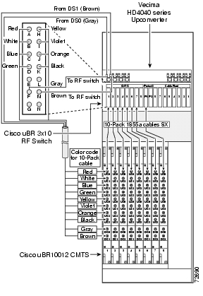
RF cables are connected to the CMTS, PROTECT and CABLE PLANT portions of the Cisco uBR 3x10 RF Switch using header blocks.
•
•
•
Figure 2 displays a detailed view of a header block that connects to a Cisco uBR 3x10 RF Switch.
Attaching the Header Blocks
Step 1
Step 2
Step 3
Caution
Mapping the RF Cables
Use the following guidelines to map cables between the Cisco uBR 3x10 RF Switch and the CMTS:
•
•
•
This mapping scenario is applicable for both working and protect cable interface line cards when employing N+1 redundancy.
Figure 2 Mapping the Cisco uBR-MC28C Cable Interface Line Cards
The distinction between which cable interface line card serves as the protect line card and which line cards serve as the working line cards is decided by which cable group (line card) is plugged into the CMTS or the PROTECT group on the RF switch, and by the configuration you specify using the information in the "N+1 Redundancy for the Cisco CMTS" chapter of the Cisco Cable Modem Termination System Feature Guide.
Connecting the RF Cables to the Header Blocks
Step 1
Step 2
Connecting to the Line Cards
Tip
Step 1
Step 2
Caution
Step 3
Output Cabling
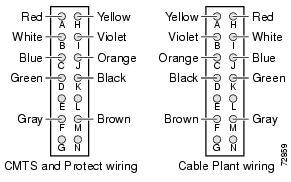
Output cable headers are wired in the reverse sequence of the input headers (see Figure 3). A cabling kit (Cisco part number CAB-RFSW-3X10⁻¹⁰T) is available from Cisco. See the Cable Plant wiring section of Figure 3.
Figure 3 Wiring the Output Cable Header
5 Part Numbers
Cisco (10-cable bundle)
CAB-RFSW-3X10⁻¹⁰T
Cisco (single cable)
CAB-RFSW-3X10-T
White Sands Engineering, Inc.
Belden1 (cable bundle)
YR46941
Belden (single cable)
YR46940
Header block
MCXHEADERBK
Extractor tool
REMTOOL
MCX connector
MCXFP
"F" connector
ASFP
MCX, "F" crimp tool
ACT-483
MCX connector strip tool:
Dual-shielded cables
PN-CPT-7538-125Dual-shielded F connector strip tool
CPT-7538
1 75-ohm precision miniature video cable
![]()
![]()
![]()
![]()
![]()
![]()
![]()
![]()
Posted: Thu Oct 25 13:47:07 PDT 2007
All contents are Copyright © 1992--2007 Cisco Systems, Inc. All rights reserved.
Important Notices and Privacy Statement.