|
|

This document provides high-level information and guidelines to assist you when configuring customer premises equipment (CPE)—for example, a Cisco 762, 1004, or 1604 router—for leased-line operation with the Cisco 90i Channel Unit. Examples for both Frame Relay and
Point-to-Point Protocol (PPP) encapsulation in Frame Relay are provided. (For information on PPP encapsulation in Frame Relay, refer to RFC-1973.)
Note The subscriber equipment can be any third-party vendor's ISDN/IDSL router or terminal adapter that supports Frame Relay or PPP and leased-line operation.
This document contains the following sections:
There are two possible ways the subscriber's CPE can be configured to set up a subscriber line from the Cisco 90i Channel Unit through a Frame Relay network to an ISP or corporate gateway router.
Each configuration is discussed in the following sections.
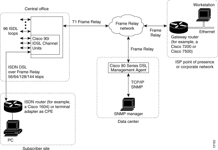
Figure 1 shows a sample configuration operating over Frame Relay protocol.
Note It is assumed, at this point, that the relevant subscriber port on the Cisco 90i has been configured for Frame Relay operation as described in the "Managing Cisco 90i. IDSL Channel Units and Subscriber Loops" chapter in the Cisco 90 Series Agent Installation Guide.
As shown in Figure 1, subscriber traffic can be transported over Frame Relay between the subscriber access equipment and the Cisco 90i. Each subscriber can have up to eight (8) Frame Relay permanent virtual circuits (PVCs) provisioned for traffic. From the subscriber perspective, depending on the PVCs provisioned on the Frame Relay network, PVCs with DLCIs in the range 16-23 are visible on the subscriber loop. Any traffic sent on one of these DLCIs is automatically mapped to the appropriate network PVC by the Cisco 90i. No additional configuration is necessary for this translation to occur. Traffic is then transported across the Frame Relay network to the ultimate destination—a Frame Relay-capable router—and the PVC terminated just like any other Frame Relay PVC.
The Cisco 90i also supports the use of the Annex D Local Management Interface (LMI) on the subscriber loop in Frame Relay mode. If the subscriber equipment sends Annex D messages, the Cisco 90i will respond appropriately. Note that Annex D LMI on the subscriber loop is not required for traffic to be transported. The Cisco 90i will allow subscriber traffic to be sent and received even if Annex D is not active. We recommend, however, that you use Annex D LMI if it is supported on the subscriber equipment.
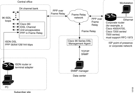
Following is a sample configuration showing the subscriber running PPP to the corporate gateway router.
Note It is assumed, at this point, that the relevant subscriber port on the Cisco 90i has been configured for PPP operation as described in the "Managing Cisco 90i. IDSL Channel Units and Subscriber Loops" chapter in the Cisco 90 Series Agent Installation Guide.
PPP operation is supported primarily to allow the use of low-cost ISDN terminal adapters and routers. Unlike Frame Relay, PPP supports only a single destination for subscriber traffic to be defined. This, however, is usually acceptable for Internet users or telecommuters. The Cisco 90i also treats the subscriber loop as a single, wide data pipe rather than as multiple channels, the way traditional ISDN equipment does. This eliminates the need for multilink PPP (MLPPP) and increases throughput by reducing the protocol overhead.
Using PPP with the Cisco 90i differs in one other significant way from Frame Relay operation. Because all traffic must be ultimately carried over a Frame Relay network, PPP has to be encapsulated in Frame Relay for the trip. The Cisco 90i uses PPP over Frame Relay encapsulation, defined by IETF RFC 1973, to automatically place PPP traffic from the subscriber into a Frame Relay frame and likewise extract PPP traffic from Frame Relay that is destined for the subscriber.
Using PPP requires that the destination router support RFC-1973 encapsulation. Cisco IOS fully supports RFC-1973 traffic. PPP traffic, once removed from Frame Relay, can be terminated and authenticated using standard authentication, authorization, and accounting (AAA) servers. Traffic can also be tunnelled over L2F/L2TP tunnels to be terminated and authenticated elsewhere. Refer to your Cisco and third-party product documentation for information regarding configuring RFC-1973 functions and operations.
Following is a sample configuration file for Cisco 700 series routers. These settings reflect a Cisco 700 series router as customer premises equipment running PPP in leased-line operation with the Cisco 90i in the network configuration shown in Figure 2.
The settings that are relevant to the Cisco 90i configuration are shown in bold. For current information on what Cisco IOS configuration settings to use for your network topology, see the software configuration guide for your platform.
Note This configuration sets the loop speed to 128 kbps; however, 56-, 64-, and 144-kbps speeds can also be supported. Consult the product documentation for the devices in your configuration (routers, terminal adapters, and so on) for specific information on supported options.
Following is a sample configuration file for the Cisco 1004 or Cisco 1604 in PPP mode.
The settings that are relevant to the Cisco 90i configuration are shown in bold. For current information on what Cisco IOS configuration settings to use for your network topology, see the software configuration guide for your platform.
Note This configuration sets the loop speed to 128 kbps; however, 56-, 64-, and 144-kbps speeds can also be supported. Consult the product documentation for the devices in your configuration (routers, terminal adapters, and so on) for specific information on supported options.
The Motorola BitSurfer Pro currently only works with the Cisco 90i at 64 kbps in PPP leased-line mode.
Testing was done using the BitSurfer Pro at 64 kbps using either CHAP or PAP authentication.
An external BitSurfer Pro was used and connected to the serial port of a Windows 95 PC. An internal PC card version of the BitSurfer Pro is also available. Windows 95 dialup networking is used to make the call.
To configure the Motorola BitSurfer Pro, perform Tasks 1 and 2, and then select Task 3 (for CHAP authenication) or Task 4 (for PAP authentication).
Task 1: Install a New Modem Definition
To support the Motorola BitSurfer Pro and Windows 95 Dialup networking, a new modem definition has to be installed.
Step 2 Click Modems.
Step 3 Modem Properties should appear. Click Add.
Step 4 Click Don't detect my Modem, I will select it from a list.
Step 5 When it asks for the modem type, select Have Disk.
Step 6 Install ISDN Surfer Setup disk 1. This has the BitSurfer Pro information for Windows 95.
Step 7 Click BitSurfer PRO I.
Step 8 Select the port to use with this modem.
Step 9 Click Finish.
Task 2: Configure the Modem for 64 kbps and PPP
To configure the Motorola BitSurfer for 64-kbps, leased-line and PPP, do the following:
Step 2 To test if you are communicating with Motorola BitSurfer, type AT.
AT should display on the screen.
Step 3 Press Enter.
When the screen displays OK, you can proceed with defining the BitSurfer by entering the following commands as appropriate for your network.
Note To use Motorola BitSurfer Pro terminal adapter, you need at least Revision K software. You can determine which version you are running by issuing the ATI8 command. If you do not have Revision K, level, you need to upgrade the Motorola BifSurfer Pro software before proceeding.
Task 3: Make a Connection Using Windows 95 and PAP
To make a connection using Windows 95 and PAP, do the following:
Use Windows 95 dialup networking to make a connection. The BitSurfer defaults to PAP authentication. To make the connection, type B1 as the phone number, this will start leased-line on one channel.
Step 2 Select a modem by clicking Use BitSurfer Pro. This modem should have already been installed.
Step 3 Enter the telephone number, B1.
Step 4 Click on your new dialup profile and use your username and password to connect.
Task 4: Make a Connection Using Windows 95 and CHAP
To make a connection using Windows 95 and CHAP, do the following:
Step 2 Select a modem by clicking Use BitSurfer Pro. This modem should have already been installed.
Step 3 Click on configure, connections, and advanced. In the "extra settings" field, type @m2=c.
Step 4 Enter the telephone number, B1.
Step 5 Click on your new dialup profile and use your username and password to connect.
Cisco Connection Online (CCO) is Cisco Systems' primary, real-time support channel. Maintenance customers and partners can self-register on CCO to obtain additional information and services.
Available 24 hours a day, 7 days a week, CCO provides a wealth of standard and value-added services to Cisco's customers and business partners. CCO services include product information, product documentation, software updates, release notes, technical tips, the Bug Navigator, configuration notes, brochures, descriptions of service offerings, and download access to public and authorized files.
CCO serves a wide variety of users through two interfaces that are updated and enhanced simultaneously: a character-based version and a multimedia version that resides on the World Wide Web (WWW). The character-based CCO supports Zmodem, Kermit, Xmodem, FTP, and Internet e-mail, and it is excellent for quick access to information over lower bandwidths. The WWW version of CCO provides richly formatted documents with photographs, figures, graphics, and video, as well as hyperlinks to related information.
You can access CCO in the following ways:
For a copy of CCO's Frequently Asked Questions (FAQ), contact cco-help@cisco.com. For additional information, contact cco-team@cisco.com.
Note If you are a network administrator and need personal technical assistance with a Cisco product that is under warranty or covered by a maintenance contract, contact Cisco's Technical Assistance Center (TAC) at 800 553-2447, 408 526-7209, or tac@cisco.com. To obtain general information about Cisco Systems, Cisco products, or upgrades, contact 800 553-6387, 408 526-7208, or cs-rep@cisco.com.
![]()
![]()
![]()
![]()
![]()
![]()
![]()
![]()
Posted: Tue Jan 21 01:24:56 PST 2003
All contents are Copyright © 1992--2002 Cisco Systems, Inc. All rights reserved.
Important Notices and Privacy Statement.