|
|

Table Of Contents
Grounding Requirements for Voice Interface Cards
Cisco 2600 Series, Cisco 3600 Series, and Cisco 3700 Series Routers
Pinout and Cabling Specifications
Foreign Exchange Station (FXS) Interface Cards
Foreign Exchange Office (FXO) Interface Cards
Setting Jumpers on the 2-Port FXO Card
Receive and Transmit (E&M) Interface Cards
Connecting E&M Interface Cards
FXS, FXO, and E&M Interface Card LEDs
Connecting ISDN BRI Interface Cards
Analog Direct Inward Dial (DID) Interface Cards
Connecting an Analog DID Interface Card
Multiflex Trunk Interface Cards
Centralized Automated Message Accounting Trunk Protocol Interface Cards
Product Information and Supported Hardware and Software
Obtaining Documentation, Obtaining Support, and Security Guidelines
Voice Interface Cards
Revised: 6/7/07, OL-12847-01Overview
Voice network modules convert telephone voice signals into a form that can be transmitted over an IP network, and have no connectors. Voice interface cards (VICs) provide the connection to the telephone equipment or network.
This document describes Cisco voice interface cards and how to connect Cisco voice interface cards to a network, and contains the following sections:
•
Grounding Requirements for Voice Interface Cards
•
•
•
•
•
•
•
Grounding Requirements for Voice Interface Cards
This section tells where to find instructions on how to properly ground voice interface cards on the following platforms:
•
Warning
Warning
Warning
Warning
Cisco 1700 Series Routers
Grounding on a Cisco 1700 series router is done on the router chassis itself, not on the voice interface cards. For information on chassis grounding on Cisco 1700 series routers, see the hardware installation guide for your router.
Cisco 2600 Series, Cisco 3600 Series, and Cisco 3700 Series Routers
The requirements in this section apply to only the Cisco 2600 series, Cisco 3600 series, and Cisco 3700 series routers.
The cards in this chapter are suitable for exposed plant lead connection. However, the host router chassis must have a permanent protective earth connection before you connect a voice interface card to an exposed plant lead. Make sure that a permanent earth connection is in place before installing the card.
If you find that a router chassis does not have an earth connection and you do not have a grounding kit, take one of the following actions:
•
•
Cisco ICS 7750
The Cisco ICS 7750 chassis has a grounding lug that needs to be properly connected using a green and yellow 14 American Wire Gauge (AWG) grounding wire. See the "Installing the Cisco ICS 7750" chapter in the Cisco ICS 7750 Hardware Installation Guide.
Pinout and Cabling Specifications
Note
Foreign Exchange Station (FXS) Interface Cards
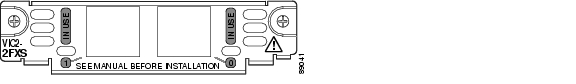
A Foreign Exchange Station (FXS) interface connects directly to a standard telephone, fax machine, or similar device. This interface supplies ringing voltage, dial tone, and so on to the station. The ports are shown in Figure 79, Figure 80, and Figure 81.
Caution
Note
If the REN load on any port is greater than 1, all four ports must be configured as either FXS or DID. For information about using analog DID with the 4-port FXS/DID VIC, see the "Analog Direct Inward Dial (DID) Interface Cards" section.
Note
Note
Note
Figure 79 2-Port FXS Card Front Panel (VIC-2FXS)
Figure 80 2-Port FXS Card Front Panel (VIC2-2FXS)
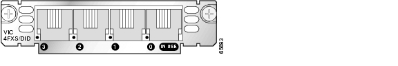
Figure 81 4-Port FXS/DID Card Front Panel (VIC-4FXS/DID)
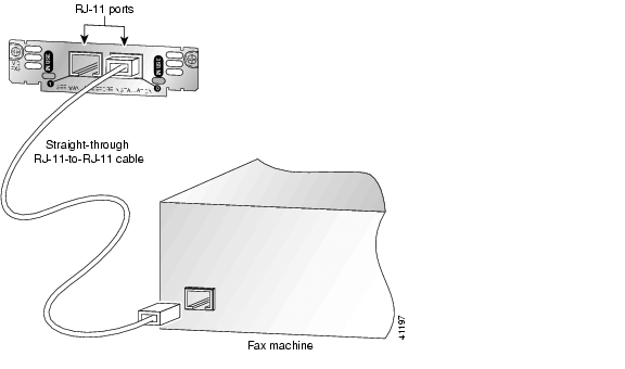
Connecting FXS Cards
Use a standard straight-through RJ-11 modular telephone cable to connect a VIC-2FXS, VIC-4FXS/DID, or VIC2-2FXS to a telephone or fax machine.
Warning
Warning
Note
Step 1
Caution
Step 2
Figure 82 Connecting an FXS Card
Step 3
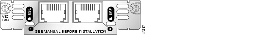
Foreign Exchange Office (FXO) Interface Cards
A Foreign Exchange Office (FXO) interface connects local calls to a central office or PBX. This is the interface a standard telephone provides. This type of card is illustrated in Figure 83, Figure 84, and Figure 85.
The VIC-2FXO and VIC-2FXO-M1 interface cards are intended for use in North America (United States, Canada, and Mexico).
The VIC-2FXO-EU and VIC-2FXO-M2 interface cards are intended for use in Europe.
The VIC-2FXO-M3 interface card is intended for use in Australia.
The VIC2-2FXO and VIC2-4FXO interface cards are software-configurable for all regions (see Figure 84 and Figure 85).
Caution
Warning
Warning
FXO
Figure 83 2-Port FXO Card Front Panel (VIC-2FXO)
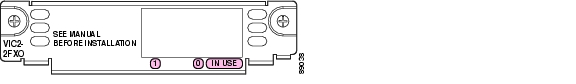
Figure 84 2-Port FXO Card Front Panel (VIC2-2FXO)
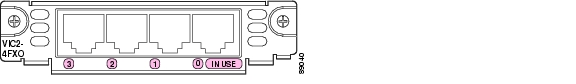
Figure 85 4-Port FXO Card Front Panel (VIC2-4FXO)
Setting Jumpers on the 2-Port FXO Card
Note
The FXO voice interface card includes two jumper headers, W3 and W4, to set loop-start or ground-start mode. One jumper configures each FXO port. The default setting is loop-start, which should be satisfactory in most installations. In this setting, jumpers are placed over positions 2 and 3 of headers W3 and W4.
Most modern central office equipment, such as DMS-100 and 5ESS switches, provides calling party control (CPC) and Ring on Seize on loop-start lines. CPC allows quicker disconnection, and Ring on Seize minimizes glare (collision of inbound and outbound calls on the same interface).
If your central office does not provide these features on loop-start, you may want to configure the FXO card for ground-start operation instead by moving the jumpers to positions 1 and 2.
For proper operation, both jumpers on the VIC-2FXO card must be configured identically.
Note
Connecting FXO Cards
Use a straight-through RJ-11 cable to connect the FXO voice interface card to the PSTN or PBX through a telephone wall outlet.
Note
Step 1
Caution
Step 2
Figure 86 Connecting an FXO Card
Step 3
Receive and Transmit (E&M) Interface Cards
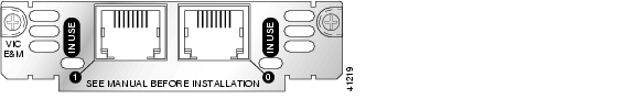
RecEive and transMit (E&M) is a signaling technique for two-wire and four-wire telephone and trunk interfaces. The E&M interface typically connects remote calls from an IP network to a PBX. The cards are illustrated in Figure 87 and Figure 88.
Caution
Figure 87 2-Port E&M Card Front Panel (VIC-2E/M)
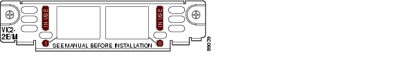
Figure 88 2-Port E&M Card Front Panel (VIC2-2E/M)
Connecting E&M Interface Cards
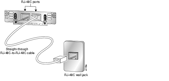
Use a straight-through RJ-48C cable to connect the E&M card to the PSTN or PBX through a telephone wall outlet.
Caution
Note
Step 1
Caution
Step 2
Figure 89 Connecting the 2-Port E&M Card
Step 3
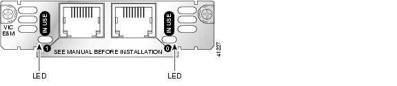
FXS, FXO, and E&M Interface Card LEDs
Each voice interface card has IN USE LEDs, one for each port. These LEDs have three states: green when active, off when ready for use, and amber when not ready for use. Figure 90 shows a voice interface card with an E&M interface as an example.
Figure 90 Voice Interface Card LEDs
ISDN BRI Interface Cards
The ISDN BRI S/T voice interface card provides a client-side (TE) ISDN S/T physical interface for connection to an NT1 device terminating an ISDN telephone network. Each port on the interface card can carry two voice calls (one over each ISDN B channel), for a total of four calls per ISDN BRI card.
ISDN BRI NT/TE voice interface cards (VIC-2BRI-NT/TE and VIC2-2BRI-NT/TE) have the same capabilities as the S/T card, but can also be configured to provide a network termination (NT) interface with phantom power.
The Cisco 1751 and Cisco 1760 routers, and the Cisco ICS 7750 platform support both ISDN BRI NT/TE voice interface cards. You can install these cards in any interface card slot in these platforms. These platforms do not support the ISDN BRI S/T voice interface card.
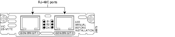
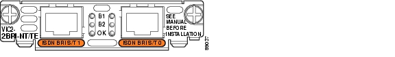
The ISDN BRI NT/TE cards are illustrated in Figure 91 and Figure 92.
Caution
Figure 91 2-Port ISDN BRI Card Front Panel (VIC-2BRI-NT/TE)
Figure 92 2-Port ISDN BRI Card Front Panel (VIC2-2BRI-NT/TE)
ISDN BRI Card Considerations
Note
Note
Note
To use all four voice channels, you must install the ISDN BRI card in slot 0 of a two-slot voice network module (NM-2V). Slot 1 should remain empty.
Note
If you install any of the following configurations, the Cisco IOS software disables certain ports, as shown in Table 24:
•
•
•
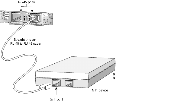
Connecting ISDN BRI Interface Cards
Use a straight-through RJ-45 cable to connect ISDN BRI cards to the ISDN network through a telephone wall outlet or other device.
Caution
To connect the 2-port ISDN BRI card to the router, follow these steps:
Step 1
Caution
Step 2
Figure 93 Connecting the 2-Port ISDN BRI Card
Note
Table 25 Interface Pin Numbers and Functions
Pin 3/T+
Pin 3/R+
Pin 3/T+
Pin 4/R+
Pin 4/T+
Pin 4/R+
Pin 5/R-
Pin 5/T-
Pin 5/R-
Pin 6/T-
Pin 6/R-
Pin 6/T-
1 Use a straight-through cable for NT interfaces.
2 Use a crossover cable for TE interfaces.
Step 3
ISDN BRI Interface Card LEDs
ISDN BRI voice interface cards have three LEDs, as listed in Table 26.
Table 26 ISDN BRI Voice Interface Card LEDs
B1
Call active on B1 channel
B2
Call active on B2 channel
OK
Interface is connected to an ISDN network
Analog Direct Inward Dial (DID) Interface Cards
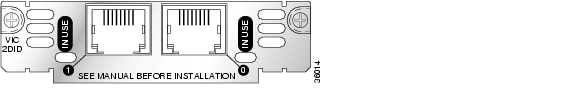
A Direct Inward Dial (DID) voice interface provides DID service to extensions on a PBX. Figure 94 shows the VIC-2DID card, and Figure 95 shows the VIC-4FXS/DID card.
Caution
Note
If the REN load on any port is greater than 1, all four ports must be configured as either FXS or DID. For information about using FXS with the 4-port FXS/DID VIC, see the "Foreign Exchange Station (FXS) Interface Cards" section.
Note
Figure 94 2-Port Analog DID Voice Interface Card
Figure 95 4-Port Analog FXS/DID Voice Interface Card
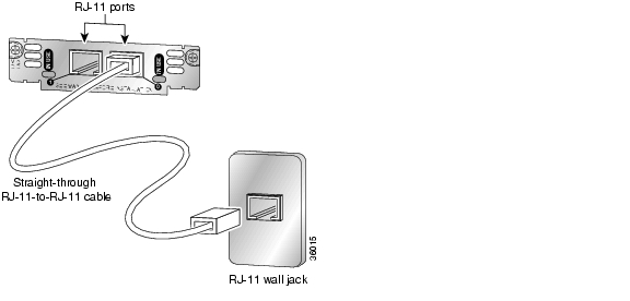
Connecting an Analog DID Interface Card
Use a standard straight-through RJ-11 modular telephone cable to connect the VIC-2DID or VIC-4FXS/DID interface card to a PSTN or PBX.
Step 1
Caution
Step 2
Step 3
Figure 96 Connecting an Analog DID Interface Card
Caution
Step 4
Multiflex Trunk Interface Cards
Multiflex trunk interface cards support generic 1- or 2-port T1 or E1 trunk interfaces for voice, data, and integrated voice and data applications. These cards provide basic structured and unstructured service for T1 or E1 networks.
They can be used as trunk interfaces for voice and data services, as fractional n x 64-kbps service for WANs (Frame Relay or leased line), or for time-division multiplexing (TDM) drop-and-insert (voice and data integration) services.
Multiflex trunk interface cards provide voice and data access to the PSTN domain through TDM ports, and include an integrated channel service unit/data service unit (CSU/DSU).
Some 2-port multiflex trunk interface cards also support the drop-and-insert process, which adds data to a T1 or E1 data stream, or terminates data from a T1 or E1 data stream to other devices connected to the drop-and-insert equipment.
Caution
This section describes the following multiflex trunk interface cards:
•
•
•
•
•
•
Caution
•
•
•
•
Note
•
•
Note
The following multiflex trunk interface cards provide hardware echo cancellation features through an echo canceler expansion module, installed on the main board of the interface card:
•
•
•
•
The following expansion modules are available:
•
•
For information on echo canceler expansion module installation, see the Installing Echo Canceler Expansion Modules on Cisco Interface Cards document.
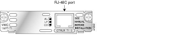
See Figure 97 for a sample 1-port multiflex trunk interface card, and Figure 98 for a sample 2-port multiflex trunk interface card.
Figure 97 1-Port T1/E1 Multiflex Trunk Interface Card Faceplate (VWIC-1MFT-T1)
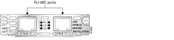
Figure 98 2-Port T1/E1 Multiflex Trunk Interface Card Faceplate (VWIC-2MFT-T1)
Multiflex Trunk Interface Card LEDs
Multiflex trunk interface cards have three LEDs, which are shown in Figure 97 and Figure 98 and are described in Table 27.
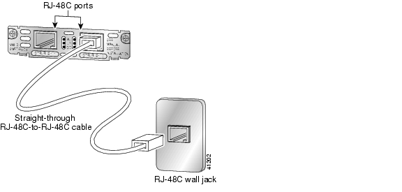
Connecting a Multiflex Trunk Interface Card
For this connection, use the straight-through RJ-48C-to-RJ-48C cable that came with your card.
Note
Confirm that the router is turned off.
Step 5
Figure 99 Connecting a Multiflex Trunk Interface Card
Step 6
Step 7
Step 8
Centralized Automated Message Accounting Trunk Protocol Interface Cards
The Centralized Automated Message Accounting (CAMA) trunk protocol interface connects local calls to emergency services. The CAMA card provides the software features required to connect directly to the enhanced 911 (E911) network from the customer premises. It also provides direct connections to a Public Service Answering Point (PSAP) using analog CAMA trunks. The CAMA protocol provides in-band signaling.
Note
CAMA Interface Cards
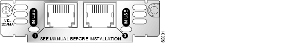
The 2-port CAMA card is illustrated in Figure 100.
Figure 100 V2-Port CAMA Card Front Panel (VIC-2CAMA)
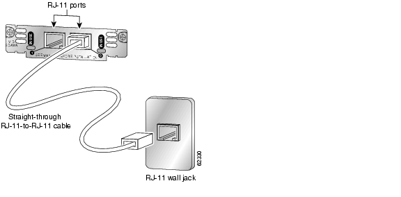
Connecting the CAMA Interface Card
Use a straight-through RJ-11 cable to connect the VIC-2CAMA voice interface card to the PSTN or PBX through a telephone wall outlet.
Note
Step 1
Step 2
Figure 101 Connecting the 2-Port CAMA Card
Step 3
Related Documentation
Related documentation is available on Cisco.com or on the Product Documentation DVD. For more information, see the "Obtaining Documentation, Obtaining Support, and Security Guidelines" section.
Product Information and Supported Hardware and Software
•
•
•
•
•
•
•
•
•
•
•
•
•
•
•
•
•
•
•
•
•
•
•
•
•
•
•
•
•
•
•
•
•
•
•
•
•
•
•
•
Obtaining Documentation, Obtaining Support, and Security Guidelines
For information on obtaining documentation, obtaining support, providing documentation feedback, security guidelines, and also recommended aliases and general Cisco documents, see the monthly What's New in Cisco Product Documentation, which also lists all new and revised Cisco technical documentation, at:
http://www.cisco.com/en/US/docs/general/whatsnew/whatsnew.html
Any Internet Protocol (IP) addresses used in this document are not intended to be actual addresses. Any examples, command display output, and figures included in the document are shown for illustrative purposes only. Any use of actual IP addresses in illustrative content is unintentional and coincidental.
© 2007 Cisco Systems, Inc. All rights reserved.
![]()
![]()
![]()
![]()
![]()
![]()
![]()
![]()
Posted: Mon Nov 26 23:56:13 PST 2007
All contents are Copyright © 1992--2007 Cisco Systems, Inc. All rights reserved.
Important Notices and Privacy Statement.