|
|

Table Of Contents
G.SHDSL High Speed WICs (HWICs)
Connecting a DSL Interface Card to the Network
Connecting the DSL Ports on WICs and HWICs
Connecting the ISDN Ports on HWICs
Connecting the SHDSL Port on the G.SHDSL HWICs
Using POTS Splitters and Microfilters with an ADSL-over-POTS WIC (WIC-1ADSL)
Common Splitter and Microfilter Configurations
Obtaining Documentation, Obtaining Support, and Security Guidelines
DSL Interface Cards
Revised: 12/06/07, OL-12846-01Overview
This document describes Cisco digital subscriber line (DSL) interface cards and how to connect Cisco DSL interface cards to a network. It contains the following sections:
•
G.SHDSL High Speed WICs (HWICs)
•
•
•
•
•
For an overview of Cisco interface cards used for Cisco access routers see the Cisco Interface Cards for Cisco Access Routers document.
ADSL WICs
The DSL wide area network (WAN) interface cards (WICs) support one DSL line between a single customer premises equipment (CPE) subscriber and a central office.
Asymmetric digital subscriber line (ADSL) WICs are available in three variations:
•
•
•
The ADSL over POTS interface card is commonly used to provide ADSL services over ordinary telephone lines. The ADSL-over-ISDN interface card is used to provide ADSL services in those areas of the world that have extensive ISDN backbones already in place.
Note
LEDs on ADSL WICs
ADSL WICs have three LEDs, which are shown in Figure 62 and are described in Table 14.
Figure 62 ADSL and G.SHDSL WIC Front Panels
Supported Platforms
For a list of the platforms supported by a Cisco interface card refer to Platform Support for Cisco Interface Cards.
Finding Support Information for Platforms and Cisco IOS Software Images
Use Cisco Feature Navigator to find information about platform support and Cisco IOS software image support. Access Cisco Feature Navigator at http://www.cisco.com/go/fn. You must have an account on Cisco.com. If you do not have an account or have forgotten your username or password, click Cancel at the login dialog box and follow the instructions that appear.
G.SHDSL WICs
The Multirate Symmetrical High-Speed Digital Subscriber Line (G.SHDSL) cards support two or more DSL lines.
The G.SHDSL WICs are available in the following variations:
•
•
Caution
LEDs on G.SHDSL WICs
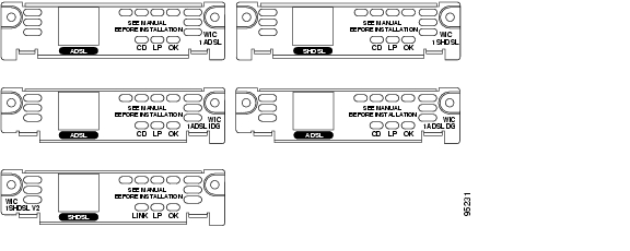
The ADSL and G.SHDSL WICs have three LEDs, which are shown in Figure 63 and are described in Table 15.
Figure 63 G.SHDSL WIC Front Panels
Supported Platforms
Table 16 lists the Cisco router platforms that are compatible with each mode available on the WIC-1SHDSL-V2 interface card.
Table 17 lists the Cisco router platforms that are compatible with each mode available on the WIC-1SHDSL-V3 interface card.
For a list of the platforms supported by a Cisco interface card refer to Platform Support for Cisco Interface Cards.
Finding Support Information for Platforms and Cisco IOS Software Images
Use Cisco Feature Navigator to find information about platform support and Cisco IOS software image support. Access Cisco Feature Navigator at http://www.cisco.com/go/fn. You must have an account on Cisco.com. If you do not have an account or have forgotten your username or password, click Cancel at the login dialog box and follow the instructions that appear.
G.SHDSL High Speed WICs (HWICs)
The G.SHDSL high speed WICs (HWICs) are available in the following variations:
•
–
–
Note
LEDs on G.SHDSL HWICs
The G.SHDSL HWICs have 4 LEDs that indicate DSL functionality. Figure 64 and Figure 65 show the front panels and LEDs for the HWIC-2SHDSL and HWIC-4SHDSL. The LED descriptions follow.
Figure 64
HWIC-2SHDSL Front Panel
Figure 65
HWIC-4SHDSL Front Panel
Supported Platforms
For a list of the platforms supported by a Cisco interface card refer to Platform Support for Cisco Interface Cards.
Finding Support Information for Platforms and Cisco IOS Software Images
Use Cisco Feature Navigator to find information about platform support and Cisco IOS software image support. Access Cisco Feature Navigator at http://www.cisco.com/go/fn. You must have an account on Cisco.com. If you do not have an account or have forgotten your username or password, click Cancel at the login dialog box and follow the instructions that appear.
ADSL High Speed WICs (HWICs)
ADSL high speed WICs (HWICs) provide ADSL support to platforms with HWIC-enabled interface slots, such as the Cisco 1800 series (modular), Cisco 2800 series, and Cisco 3800 series integrated services routers. Standard ADSL, ADSL2, ADSL2+, and Dying Gasp are supported.
ADSL HWICs are available in the following variations:
•
–
–
•
–
–
Note
ADSL HWICs are all packaged in Cisco's standard single-wide HWIC form factor.
The ADSL port is connected to the WAN with a straight-through RJ-11 cable supplied with the card.
The ISDN port is connected to an NT1 device with a straight-through RJ-45 cable, not supplied.
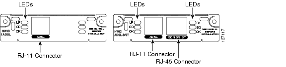
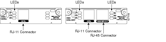
LEDs on ADSL HWICs
ADSL HWICs have 3 LEDs that indicate DSL functionality. Those ADSL HWICs with a backup ISDN port have three additional LEDs that indicate ISDN functionality.
Figure 66 and Figure 67 show the front panels and LEDs for the ADSLoPOTS and ADSLoISDN HWICs. The LED descriptions are listed in Table 18.
Figure 66 ADSLoPOTS HWIC Front Panel
Figure 67 ADSLoISDN HWIC Front Panel
Supported Platforms
For a list of the platforms supported by a Cisco interface card refer to Platform Support for Cisco Interface Cards.
Finding Support Information for Platforms and Cisco IOS Software Images
Use Cisco Feature Navigator to find information about platform support and Cisco IOS software image support. Access Cisco Feature Navigator at http://www.cisco.com/go/fn. You must have an account on Cisco.com. If you do not have an account or have forgotten your username or password, click Cancel at the login dialog box and follow the instructions that appear.
Cables
The twisted-pair straight-through cable for customer premises equipment (CPE) applications is supplied. The RJ-45-to-RJ-45 BRI cable to connect the ISDN BRI ports on ADSLoISDN HWICs is not supplied. The two-line Y-cable for central office (CO) and 4-wire patch panel applications is not supplied.
Note
Connecting a DSL Interface Card to the Network
See the following sections for information on connecting DSL interface cards to a network.
•
•
•
Connecting the DSL Ports on WICs and HWICs
Use a straight-through RJ-11 cable for this connection.
Table 19 shows the ADSL WIC and HWIC pinouts.
Note
Table 20 shows the WIC-1SHDSL pinouts.
Table 21 shows the RJ-14C pinouts on the WIC-1SHDSL-V2 and WIC-1SHDSL-V3 interface cards.
Table 21 WIC-1SHDSL-V2 RJ-14C Pinouts
3 and 4
3 = Tip, 4 = Ring
0
2 and 5
2 = Tip, 5 = Ring
1
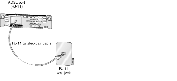
To connect a DSL interface card to the WAN, complete the following steps:
Step 1
Warning
Step 2
Step 3
Figure 68 Connecting an ADSL Card to the Wall Jack
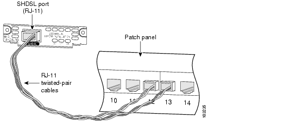
Alternately, when connecting a G.SHDSL card to a 4-wire patch panel, use a Y-cable as shown in Figure 69.
Figure 69 Connecting a G.SHDSL Card to a Patch Panel With a Y-Cable
Step 4
Step 5
Note
Connecting the ISDN Ports on HWICs
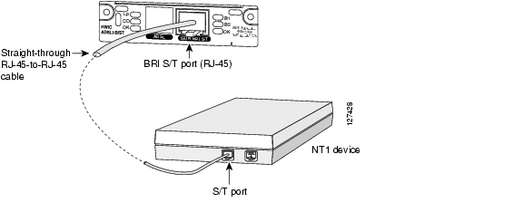
Use an RJ-45-to-RJ-45 BRI cable (not included) to connect the ISDN BRI port to an ISDN NT1 device. Refer to the online document Cisco Modular Access Router Cable Specifications for pinouts.
To connect an ISDN BRI S/T port to the WAN, follow these steps:
Step 1
Warning
Step 2
Step 3
Figure 70 Connecting the BRI S/T Port
Step 4
Step 5
Connecting the SHDSL Port on the G.SHDSL HWICs
Connect Cisco G.SHDSL HWICs as described next:
•
•
Warning
Figure 71 shows the RJ-45 pin assignment. Table 22 identifies the RJ-45 signal assignment by pin.
Caution
Figure 71
RJ-45 Pin Assignment
Table 22 RJ-45 Signal Assignment by Pin
1
Line 1 tip
2
Line 1 ring
3
Line 2 tip
4
Line 0 tip
5
Line 0 ring
6
Line 2 ring
7
Line 3 tip
8
Line 3 ring
To connect the Cisco HWIC-4SHDSLwith a DSLAM that supports two or four RJ-11 connections, modify the standard RJ-45 cable, using one of the following diagrams as applicable:
•
•
Figure 72
Standard RJ-45 Connector to Four Standard RJ-11 Connectors
Figure 73
Standard RJ-45 Connector to Two Standard RJ-11 Connectors
Using POTS Splitters and Microfilters with an ADSL-over-POTS WIC (WIC-1ADSL)
POTS splitters and microfilters apply to the ADSL-over-POTS WIC only. They are used on telephone lines to ensure voice- and data-call quality. POTS splitters result in the best data and voice performance when the router and the telephone are used on the same telephone line.
POTS Splitters
A POTS splitter (also called a splitter) is installed on a telephone line that is connected to both data (high-frequency) and voice (low-frequency) devices. The splitter routes the high-frequency and low-frequency signals on the telephone line to the correct device. Signals intended for the router can disrupt voice calls; signals intended for voice calls can affect router operation.
Most splitters must be installed by the telephone company; however, some splitters can be installed by the customer. If you are not sure what type of splitter to use, contact your service provider.
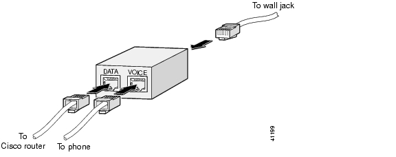
Figure 74 is an example of a type of POTS splitter that is installed at the customer premises by the customer. Other types of POTS splitters are installed by the telephone company on an exterior wall of the customer premises.
Figure 74 POTS Splitters
Microfilters
Microfilters are installed on telephones to improve voice-call quality when voice and data equipment are using the same telephone line (twisted pair). You should use microfilters only when the two following conditions exist:
•
•
Figure 75 shows one type of microfilter.
Figure 75 Microfilter
Common Splitter and Microfilter Configurations
This section describes the most common scenarios for using splitters and microfilters. The scenarios are listed from most common to least common.
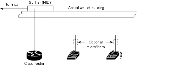
Telephone Company-Installed Splitter
This scenario is described below and illustrated in Figure 76.
•
•
•
•
Figure 76 Telephone Company-Installed Splitter
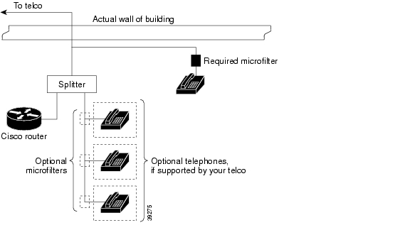
Customer-Installed Splitter
This scenario is described below and illustrated in Figure 77.
•
•
•
•
•
•
Figure 77 Customer-Installed Splitter
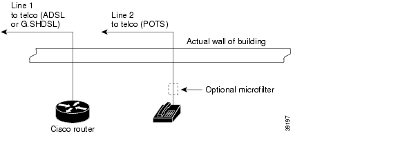
Router and Telephone Using Separate Telephone Lines
This scenario is described below and illustrated in Figure 78.
•
•
Figure 78 No Splitter, Optional Microfilter
Related Documentation
Related documentation is available on Cisco.com or on the Product Documentation DVD. For more information, see the "Obtaining Documentation, Obtaining Support, and Security Guidelines" section.
Feature Modules
–
–
–
–
–
–
–
–
–
–
Sample Configurations
–
–
–
–
–
–
–
–
–
–
–
–
–
–
–
Obtaining Documentation, Obtaining Support, and Security Guidelines
For information on obtaining documentation, obtaining support, providing documentation feedback, security guidelines, and also recommended aliases and general Cisco documents, see the monthly What's New in Cisco Product Documentation, which also lists all new and revised Cisco technical documentation, at:
http://www.cisco.com/en/US/docs/general/whatsnew/whatsnew.html
Any Internet Protocol (IP) addresses used in this document are not intended to be actual addresses. Any examples, command display output, and figures included in the document are shown for illustrative purposes only. Any use of actual IP addresses in illustrative content is unintentional and coincidental.
© 2007 Cisco Systems, Inc. All rights reserved.
![]()
![]()
![]()
![]()
![]()
![]()
![]()
![]()
Posted: Fri Dec 7 08:32:15 PST 2007
All contents are Copyright © 1992--2007 Cisco Systems, Inc. All rights reserved.
Important Notices and Privacy Statement.