|
|

Table Of Contents
Cisco Catalyst 6500 Series Wireless LAN Services Module: Detailed Design and Implementation Guide
AP-based WDS and Switch-based WDS
New Concept—VLAN on the Access Point
Scalability of the WLSM Solution
AP-based WDS and Switch-based WDS—Can They Coexist?
RADIUS-based Dynamic Mobility Group Assignment
IP Addressing Scheme Recommendations
GRE and Issues with Fragmentation
Design Limitations and Caveats
Implementing Quality of Service
Applying Catalyst 6500 Features to Wireless Traffic
Catalyst 6500 Service Module Integration
Cisco Catalyst 6500 Series Wireless LAN Services Module: Detailed Design and Implementation Guide
Introduction
This is the first of a series of documents on the design and implementation of a wireless network with the Cisco Catalyst 6500 Series Wireless LAN Services Module (WLSM).
Audience
This document is intended primarily for system engineers who are responsible for designing and implementing wireless network solutions with the Cisco Catalyst 6500 Series WLSM. The audience should be familiar with terms such as the Cisco Structured Wireless-Aware Network (SWAN), Wireless Domain Services (WDS), Fast Secure Roaming (FSR), and with terminology associated with the Cisco Catalyst 6500.
Document Objectives
This document provides design and deployment recommendations for the implementation of a campus wireless solution with the WLSM. All the recommendations given in this document are based on proof of concept tests.
The document includes the following sections:
•
Overview
Overview
Cisco SWAN provides the framework to integrate and extend wired and wireless networks to deliver the lowest possible total cost of ownership for companies deploying WLANs. Cisco SWAN extends "wireless awareness" into important elements of the network infrastructure, providing the same level of security, scalability, reliability, ease of deployment, and management for wireless LANs that organizations have come to expect from their wired LANs. The Cisco SWAN framework includes the following components:
•
•
•
•
•
This section includes the following topics:
•
Cisco SWAN WDS
Cisco SWAN uses WDS to deliver wired and wireless integration. WDS is a collection of Cisco IOS Software features that enhance WLAN client mobility and simplify WLAN deployment and management. A WDS device can be a Cisco AP, switch, or router. Cisco SWAN delivers different functionality depending upon where WDS is located.
When AP-based WDS is used, Cisco SWAN supports Layer 2 FSR, scalable WLAN management, advanced radio management (RM) capabilities, and enhanced wireless security. When switch-based WDS is used, Cisco SWAN supports Layer 2/Layer 3 FSR, advanced RM capabilities, end-to-end security, and end-to-end quality of service (QoS) in campus WLAN deployments. This document addresses Cisco Catalyst switch-based WDS on a Cisco Catalyst 6500 Series WLSM.
AP-based WDS and Switch-based WDS
Using switch-based WDS and the Cisco Catalyst 6500 WLSM blade provides enhanced capabilities for the design and deployment of the Cisco WLAN architecture. Reviewing the features of a Cisco SWAN AP-based WDS deployments helps to better understand these changes.
Cisco SWAN AP-based WDS provides a Layer 2 mobility solution with the following considerations from a network design perspective:
•
•
•
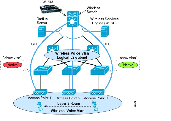
As shown in Figure 1, the implementation of AP-based WDS FSR requires a WDS AP per subnet, which requires configuration, management, and monitoring one WDS per roaming domain, with the AP-based WDS supporting a maximum of 60 APs (the number goes down to 30 if the AP acting as the WDS also accepts clients associations).
Figure 1 Fast Secure Roaming Implementation
With AP-based WDS, FSR is available when the client roams between two APs that are configured with the same VLAN on the wired side. This is Layer 2 roaming because the client remains part of the same subnet. As a consequence of such an implementation and to provide a campus-wide roaming solution, the VLAN to which the client belongs must be configured on every access switch where the APs are attached.
Cisco does not recommend spanning a VLAN across the entire campus. VLANs must be terminated at the distribution switch or first hop router to limit the Spanning Tree and broadcast domain.
The introduction of switch-based WDS and the WLSM facilitates Layer 3 FSR and provides a highly-scalable solution for Layer 3 mobility in the campus. By centralizing the functionality of WDS in the WLSM blade in a central switch, switch-based WDS provides the following benefits:
•
•
•
•
•
•
Figure 2 shows all these advantages.
Figure 2 WLSM Advantages
Required Components
Cisco SWAN Catalyst switch-based WDS consists of the following components:
•
•
•
•
•
•
In addition to the hardware requirements, the minimal software requirements for this solution are the following:
•
•
•
•
The software requirements for Cisco Secure ACS are dependent on the type of Extensible Authentication Protocol (EAP) desired. For full support of all the EAP types including EAP-Flexible Authentication via Secure Tunneling (FAST), use release 3.2.3 or higher.
Solution Description
This section includes the following topics:
•
Centralized WDS
The WLSM embeds the functionality of WDS in a service module of the Cisco Catalyst 6500 Series. With the addition of this module, the Catalyst 6500 integrates wireless and wired traffic on the same platform.
With AP-based WDS, the WDS resides on one of the APs in the subnet, and is Layer 2-connected to all the other APs that are authenticated to that WDS.
With switch-based WDS using the WLSM, the functionality of WDS is moved from the AP in one subnet to the WLSM blade in a centralized location in the network. The centralized WDS now defines the roaming domain; a subsequent section of this document explains that Layer 3 seamless roaming is provided only if the APs are part of the same roaming domain.
All the APs belonging to the same roaming domain must use Cisco LEAP to authenticate to the RADIUS server through the central WDS. This defines the infrastructure authentication. During this phase, all the APs are the clients in respect to the 802.1X authentication, and they authenticate to the network through the WLSM that acts as the Network Access Server (NAS) for the network. The WLSM also discovers all the APs that will use its service during this phase. Thus, the infrastructure authentication is not changed when either an AP-based WDS or a switch-based WDS is used.
With switch-based WDS, the Wireless LAN Context Control Protocol (WLCCP) has been modified to run on top of a Layer 3 infrastructure. The WDS and the APs are thus no longer Layer 2 adjacent, and the entire campus network is between them. Therefore, with switch-based WDS, a management VLAN does not need to span the entire campus for the APs to communicate with each other and with the WDS at Layer 2. Also, with switch-based WDS, the network administrator has only one WDS to configure and manage, reducing the management overhead.
The centralized WDS of the switch-based WDS also acts as the NAS for all the client authentications. In this way, the WDS gains knowledge of more than just all the APs in the roaming domain. This information is shared with the Layer 3 Mobility Manager on the Supervisor 720 (Sup720) and used to build the internal database.
Layer 3 Mobility Manager
The Layer 3 Mobility Manager (L3MM) is the new software subsystem that runs on the Sup720 Route Processor (RP). L3MM interacts on one side with the WDS software running on the WLSM through a new protocol called Layer 3 Control Protocol (LCP) over the Ethernet Out of Band Channel (EOBC). On the other side, the L3MM interacts with the other components of the Catalyst 6500, mainly the hardware subsystem for the implementation of generic routing encapsulation (GRE) tunnel interfaces and the programming of the forwarding table and the Dynamic Host Configuration Protocol (DHCP) snooping, all of which are for handling client registrations.
The L3MM is responsible for creating and maintaining the mobility database that contains the list of all the wireless clients registered with the WLSM. Each mobility record includes the IP and MAC address, and the AP with which it is associated.
Mobility Groups
The concept of the mobility group is one of the most important concepts introduced in Cisco SWAN switch-based WDS. With switch-based WDS, a wireless client experiences a seamless roaming (maintaining all its IP sessions) when moving between two APs configured to be part of the same mobility group.
A mobility group is defined on the AP by a unique mapping between the service set identifier (SSID) for the radio side and the network ID for the wired side. The network ID is the new element of this solution. The network ID represents the overlaid logical network built on top of the existing infrastructure using GRE tunnels, and its mapping to the SSID replaces that between the SSID and the VLAN ID.
A subsequent section of this document explains that for IP unicast traffic there is no need to define an 802.1q trunk connection between the AP and the access switch to separate the traffic coming from a different SSID. In other words, the VLAN is no longer used for traffic segmentation on the wired side of the AP. In this case, with the definition of the mobility group, the traffic from different SSIDs is carried on the wired side over different GRE tunnels to the central switch.
The mobility group is in fact also identified on the Sup720 by the configuration of a GRE tunnel interface. This interface is assigned to the mobility group by configuring the corresponding network ID. The tunnel interface acts as the default gateway for all the wireless traffic belonging to the wireless logical network and represents the single point of ingress and egress for IP unicast traffic to and from the wired network.
Multipoint GRE Technology
The mobility group represents the logical wireless subnet where the clients reside. This overlaid network is built using the mGRE technology, which enables Cisco IOS to have one GRE tunnel interface that has a manually-configured tunnel source but with dynamic tunnel destinations. In the case of a WLSM deployment, this allows the GRE tunnels to be built dynamically from the APs belonging to a mobility group to the unique tunnel interface.
The APs learn the mobility group and tunnel destination IP address mapping from the WDS via WLCCP messages during infrastructure authentication. With this information, the AP is able to create the corresponding GRE tunnel and send the traffic over it after it receives the traffic from a wireless client belonging to a certain mobility group and thus a certain SSID. On the central switch, the multipoint GRE configuration allows the supervisor to accept any tunnel dynamically created by the AP.
All the Layer 3 interfaces on the Catalyst 6500, such as routed ports and tunnel interfaces, are virtual interfaces and are assigned an internal VLAN number by the switch to manage the traffic. This VLAN is taken from the pool of the non-client VLANs; basically, any number in the range of 1025-4096. The implementation of the Sup720 for GRE tunnel interfaces requires two internal VLANs to be allocated for every tunnel interface defined on the box. To determine how many tunnels and thus mobility groups are configurable on the supervisor, use the following equation:
4096 - (1025 + number of L3 interfaces in use)/2
There is a times 2 factor for each tunnel interface present.
The number of mobility groups is currently limited by the WDS, which supports only16 on switch-based WDS.
Layer 3 Roaming with the WLSM
This section includes the following topics:
Layer 3 Roaming Overview
Mobility in a wireless LAN environment can present a challenge as the physical reach of the network grows. Applications such as voice require sub-150 ms roam times and expect IP address continuity, regardless of the Layer 3 boundaries that are crossed. Deploying a large and flat Layer 2 network can subject user traffic to delays and loss of service because of issues such as broadcast storms and Spanning Tree Protocol (STP) reconvergence times.
The Cisco Catalyst 6500 Series WLSM blade and Cisco SWAN define a Layer 3 mobility solution. This section defines Layer 3 roaming as supported by this new architecture to differentiate this solution from other possible L3 mobility solutions such as Mobile IP.
With Layer 2 roaming, the wireless client roams between two APs that are part of the same subnet on the wired side. This functionality is provided by AP-based WDS, in which the APs must be configured to be in the same VLAN (the AP management VLAN) as a result of the following design constraints:
•
•
With Layer 3 roaming, the wireless client roams between two APs that reside in two different subnets and thus two different VLANs on the wired side. This removes the creation of VLANs that span the entire campus, as are created by AP-based WDS. This is explained in more detail in the "Design Considerations" section.
Layer 3 mobility as provided by switch-based WDS provides better performance and a more scalable approach. APs may be deployed in any location in a large Layer 3 network without requiring a single VLAN to be carried throughout the wired switch infrastructure. An overlay of mGRE tunnels allows clients to roam to other APs residing on different Layer 3 subnets without loss of connectivity or a change in IP addressing.
When a mobile user associates with an access point under the control of the WLSM, the user registers with the network and is assigned to a particular mobility group. At the system level, the network ID internally defines this mobility group. The system uses the network ID to associate the user with a particular GRE tunnel. As the user roams, the system tracks the movement of the user to ensure the association is maintained with the same mobility group.
Fast Secure L3 Roaming
Fast Secure Roaming (FSR) enables wireless clients to quickly roam across or between APs. Using Cisco Centralized Key Management (CCKM), the WDS caches session credentials (security keys) derived for a client session and uses them for re-authentication when a client roams. Caching this information rather than forcing the client to do a full authentication, authorization, and accounting (AAA) authentication reduces the authentication time and therefore the total time required for roaming.
The roaming is always defined from a client perspective because the client initiates roaming. In this document, client roaming is defined as "fast" if the whole handoff process happens in less than 100 ms; this guarantees support for low latency applications such as voice over IP (VoIP). In addition, the handoff is declared "seamless" if there is no impact on existing L3 connections. The roaming time is measured from the last successful packet sent or received on one AP to the first successful frame exchanged with the new AP.
The following two conditions must occur for the roaming to be fast and seamless in a WLAN deployment with the WLSM:
•
•
The best way to describe seamless Layer 3 roaming with the WLSM is to define it as a Layer 2 roaming across a Layer 3 infrastructure: the wireless client roams between the two APs that reside in different wired subnets but are part of the same mobility group. The client remains in the same wireless logical subnet created by the mGRE tunnel architecture and thus maintains the same IP address.
The use of CCKM guarantees a very fast handoff (less than 100ms), thus the client maintains all IP sessions and does not experience any lost connectivity. At present, CCKM is supported with LEAP and EAP-FAST authentication algorithms.
Putting It All Together
This section includes the following topics:
•
•
Configuration Overview
This section describes all the basic steps required to configure a wireless solution with the WLSM. This is not meant to be a configuration guide with details on the commands to use but instead a description of how all the concepts introduced to this point come together into a working solution. The next section describes the details of how IP data traffic flows through this architecture.
Consider a simple scenario in which two APs are configured in the same mobility group. Separate the configuration into the following three steps:
1.
2.
3.
Control path traffic is considered to be all the traffic that is sourced from or destined to the AP; this includes all the management traffic and the WLCCP traffic between the AP and the WDS on the WLSM. Data traffic is defined as the traffic to and from the wireless client. The traffic is encapsulated by the AP using GRE and is sent to the central switch.
Configuring the IP Connectivity
The first requirement of the Layer 2 connection is a VLAN defined on the AP as native; this is also known as the management VLAN or the default VLAN. The AP uses this VLAN to source its traffic; WLCCP, Simple Network Management Protocol (SNMP), HTTP, and Telnet for the management traffic, and GRE for unicast IP data traffic. The same VLAN must be defined on the access switch and on the first hop router or Layer 3 switch. The IP address assigned to the AP in the native VLAN is chosen from the local addressing scheme.
Following are some IP connectivity recommendations:
•
•
•
Configuring the Control Path
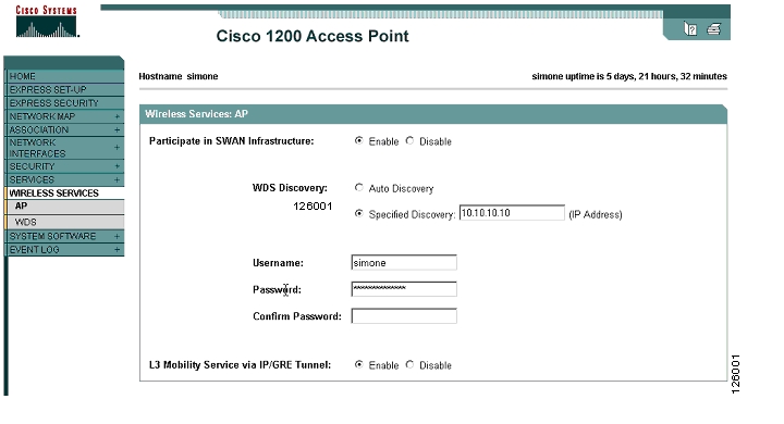
After configuring the WLSM to act as the WDS, the only other step required is to manually configure the AP with the IP address of the WDS. No auto-discovery mechanism is supported for the switch-based WDS.
Figure 3 shows the configuration through the GUI.
Figure 3 AP Configuration
Only one WDS IP address can be specified on the AP. This means that all the SSIDs that are WDS-enabled refer to the same WDS. Also, because the IP address is manually configured and WDS auto-discovery is disabled, there is no fallback to an AP-based WDS when the connection to the WLSM is lost. In this case, all the data traffic is dropped at the AP. Through WLCCP, the AP learns all the information needed to set up the data path, which is mainly the IP address of the GRE tunnel destination for each configured mobility group.
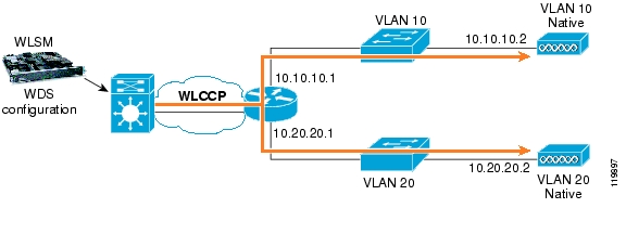
The steps seen so far are shown in Figure 4.
Figure 4 Control Path Configuration
Configuring the Data Path
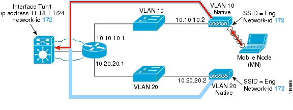
The last step in the setup of the WLSM is the configuration of the mobility group. This step defines the wireless subnet to be assigned to the wireless users and is built through the use of GRE tunnels. The mobility group is identified on the AP by the mapping between an SSID and a network ID. On the central switch, a tunnel interface must be configured with the corresponding network ID (that is, mobility group) and assigned the IP address and subnet where the wireless clients are going to reside.
After this is done, when the AP receives a packet from a client on a particular mobility group, it forwards this traffic over the corresponding GRE tunnel to the central switch. The supervisor is responsible for stripping off the GRE header and forwarding the packet to the original destination. All these processes are hardware-accelerated. Figure 5 shows these steps.
Figure 5 Configured Data Path
Traffic Flow
This section includes the following topics:
•
Traffic Flow Overview
One of the most important changes introduced by switch-based WDS and the WLSM is the way wireless traffic flows to and from the wireless users across the network infrastructure. This section describes in detail how the unicast and broadcast traffic is carried into the GRE tunnels and how the wireless network integrates with the wired infrastructure. Understanding the traffic flow in switch-based WDS is not only fundamental in correctly designing a wireless solution with the WLSM, but also helps in addressing broadcast domain definitions.
Switch-based WDS with the Cisco Catalyst 6500 WLSM and GRE tunnel technology is an IP-only solution. All the traffic that is not IP (IPX, NetBIOS, and so on) that belongs to a certain SSID is bridged by the AP on the corresponding VLAN in the same way as is done in AP-based WDS with no WLSM.
This section describes how the traffic flows for the data path; that is, the traffic to and from the wireless users. This is the traffic that is encapsulated into GRE by the AP and then switched in hardware by the Cisco Catalyst 6500. The control path, which is all the traffic originated or terminated on the AP, flows through the native infrastructure and is not covered in this section. The separation of data and control path is explained in much more detail in subsequent sections.
Unicast Traffic
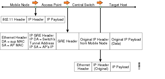
All the IP unicast traffic to and from a wireless client belonging to a certain mobility group is sent over the corresponding GRE tunnel from the AP to the GRE tunnel interface on the central switch and back again the same way. As explained in the previous sections, the tunnel interface on the supervisor represents the default gateway for all the wireless traffic belonging to the wireless logical subnet identified by the mobility group.
Consider a common scenario with a wireless client and a target host somewhere in the wired network. When the wireless client sends an IP packet, the AP receives it and looks at the source MAC address. Based on the internal forwarding database, the AP determines to which GRE tunnel to forward the packet (which basically means to which network ID the client belongs). The content of the mobility forwarding table of the AP can be shown on the command-line interface (CLI) of the AP with the following command:
AP-B#sh wlccp ap mobility forwardingWireless Control(0002.7e07.8000) IPv4 Forwarding TableMAC Address IP address Tunnel address000d.bcfe.33f6 172.16.1.100 10.10.200.1000a.b74c.af0b 172.16.1.101 10.10.200.1The AP then strips off the 802.11 header, encapsulates the IP packet in GRE, adds the IP/Ethernet header sourced from its own IP/MAC address, and finally sends it to the Cisco Catalyst 6500.
After receiving the GRE-encapsulated packet from one of its physical interfaces, the supervisor processes it in hardware. This means that after the Ethernet header has been stripped off, the Policy Feature Card (PFC) performs a first lookup and decapsulates the packet. The adjacency points the packet to a second recursive lookup in which the PFC determines where to forward the packet. Finally, the Ethernet header is added and the frame is sent out the physical interface to the next hop.
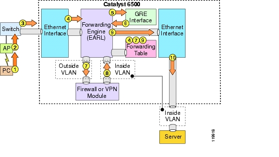
Figure 6 shows all these steps.
Figure 6 Unicast Traffic—From Wireless Client to Target Host
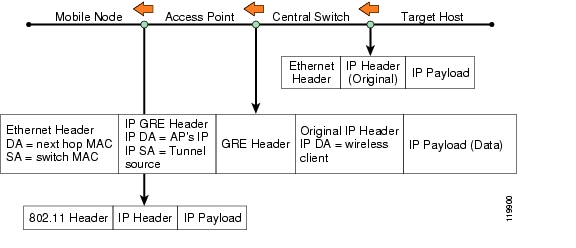
The return traffic takes a similar path, as shown in Figure 7.
Figure 7 Unicast Traffic—Return Traffic
After receiving the traffic destined to the wireless user, the central switch looks at the mobility database to determine to which mobility group and thus over which GRE tunnel to send the packet. The central switch then encapsulates the packet with a new header using the AP IP address and forwards it to the AP. The AP first strips off the GRE header and then performs a mobility forwarding table lookup based on the received destination IP address of the original packet. In this way, the AP learns the MAC address to use to form the 802.11 header and then forwards the packet into the air.
All unicast traffic sourced from wireless users always goes over the GRE tunnel to the central switch where the forwarding decision is made. To better clarify the traffic flow, consider these two other scenarios:
•
•
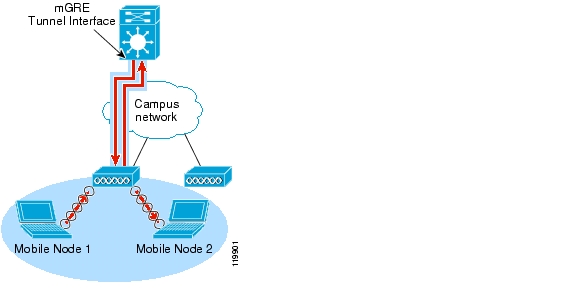
In the first scenario (see Figure 8), Mobile Node 1 and 2 are associated to the same AP and have the same SSID configuration; thus they are part of the same logical wireless subnet.
Figure 8 Traffic Between Wireless Clients—Same AP and Same Mobility Group
Mobile Node 1 sends a packet to Mobile Node 2. The AP gets the frame and forwards it over the GRE tunnel associated to the mobility group. When the supervisor gets the packet and sees that the destination is on the same wireless subnet, it then makes a L2 switching decision and sends the packet back over the same tunnel from which it came. The AP decapsulates it and forwards it into the air.
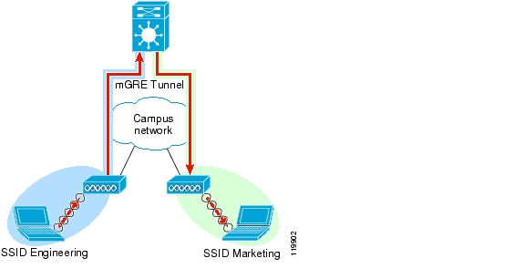
In the second scenario (see Figure 9), Mobile Node 1 and 2 belong to two different wireless subnets (mobility group "blue" and "green" with SSID Engineering and Marketing respectively).
Figure 9 Traffic Between Wireless Clients—Different AP and Different Mobility Group
The traffic from Mobile Node 1 is forwarded over the blue GRE tunnel to the central switch. In this case, because the destination resides in another mobility group, a full L3 routing decision occurs. The supervisor first determines from which interface to send the packet out; it then examines its mobility database and determines which other interface tunnel to use to forward the packet. The supervisor uses the AP IP address to form the GRE packet and sends it to the AP where Mobile Node 2 is associated.
Broadcast Traffic
This section includes the following topics:
Broadcast Traffic Overview
To roam seamlessly, the wireless client must move between APs that belong to the same mobility group. In this way, the client remains in the same wireless subnet and is able to maintain that same IP address while roaming.
Cisco SWAN switch-based WDS with the WLSM supports up to 6000 users, who can be part of the same mobility group and thus part of the same wireless subnet or broadcast domain.
Concerns may arise about the amount of broadcast traffic this generates on the network and on how the solution scales with such a large broadcast domain. Understanding how IP broadcast traffic is managed by the WLSM solution is fundamental not only to a correct deployment of a wireless LAN solution with the Cisco Catalyst 6500 WLSM but also to address these concerns. The following sections examine the different types of broadcast packets and how they flow across this architecture.
Note
ARP Traffic
One of the significant architectural changes brought by the introduction of the switch-based WDS and the WLSM is related to how the AP manages Address Resolution Protocol (ARP) frames received by locally associated wireless clients. Before the introduction of the WLSM, the AP acted as a bridge for ARP frames, simply forwarding the broadcast frame to the local VLAN corresponding to the client SSID. With Cisco SWAN switch-based WDS and for the SSIDs that are WLSM-enabled, two different AP behaviors can be identified, based on the types of ARP frame sent by the wireless clients and received by the AP: ARP requests and gratuitous ARP (GARP) queries.
When the wireless client sends a broadcast ARP request frame to map an IP address to the corresponding MAC address, the AP intercepts this frame and replies to the client with the supervisor MAC address. The AP proxies all the wireless ARP requests and replies with the same MAC address it learns during the infrastructure authentication from the WDS. The reason for this behavior is that all the unicast IP traffic, no matter what the destination, must go through the supervisor, even if the destination is another wireless client associated to the same AP. As a consequence, no broadcast ARP traffic is sent over the GRE tunnel, which limits the amount of broadcast traffic allowed on the wired infrastructure.
The solution is automatically protected from malicious attacks based on a Layer 2 port scan. If a wireless attacker performs a Layer 2 port scan to discover who else is on the same subnet, the attacker gets only one single MAC address, which renders the attack useless.
With the GARP frame, for example, a wireless client sends the broadcast ARP message after being assigned a DHCP address to avoid IP address duplication. In this case, when the AP receives this message and identifies it as a GARP message, it forwards it over the tunnel. The supervisor receives it and checks its mobility database for any duplication. If no other client has the specified IP address, the supervisor drops the packet. Otherwise, it replies on behalf of the other wireless node. At this point, the operating system of the client that originated the GARP triggers the warning that a "duplicated IP address" exists in the network.
Another important thing to notice here is that with wireless traffic, the supervisor forwards traffic based on the mobility database, not the local ARP cache. Thus, an attack aimed at poisoning the ARP cache of the central switch (for example, a man-in-the-middle type of attack) has no effect on wireless traffic. This provides enhanced security for the WLAN.
DHCP Traffic
DHCP traffic is another very common type of broadcast traffic. This section explains how DHCP is managed by the AP and the Sup720 for the wireless client in a WLSM deployment.
When the client sends a DHCP request, the AP forwards it into the tunnel to the supervisor. If configured, the central switch relays this traffic to the DHCP server where the network administrator has configured the scope for wireless clients belonging to that mobility group. The other option is to configure the DHCP server directly on the Cisco IOS of the supervisor.
The important thing to notice here is that no DHCP traffic coming from an AP is going to be forwarded over the other GRE tunnels to an AP that is part of the same mobility group. This reduces the amount of broadcast traffic on the network.
IP Broadcast Traffic
Some wireless applications use a general broadcast or a subnet-directed broadcast to communicate to the clients. Consider this packet flow: the wireless client sends a packet destined to 255.255.255.255; the AP receives it and then forwards it over the GRE tunnel to the supervisor. By default, the switch drops this traffic, which prevents the broadcast from reaching other APs in the same mobility groups and thus other wireless clients in the same wireless subnet. If forwarding the broadcast traffic is desired, you can manually instruct the supervisor to duplicate all the broadcast packets received from one GRE tunnel to all the other GRE tunnels belonging to the same mGRE interface. You do this by configuring "mobility broadcast" directly under the tunnel interface.
By default in Cisco IOS, the tunnel interfaces have the no ip directed-broadcast command enabled, which prevents any broadcast from being forwarded through that interface. Remember to issue the ip directed-broadcast command together with the mobility broadcast command.
For broadcast traffic originating from the wired network and destined to all the clients in the wireless subnet (such as the case of a subnet-directed broadcast), the supervisor receives the packet and if the tunnel interface for that mobility group is configured with mobility broadcast, the supervisor duplicates the packets to all the GRE tunnels that belong to the mGRE interface that has received the broadcast.
IP Multicast Traffic
This section includes the following topics:
•
•
IP Multicast Traffic Overview
The introduction of the WLSM significantly changes how the AP manages IP multicast traffic, and has important consequences for the design of a multicast-enabled wireless network solution.
To understand how IP multicast traffic flows, important distinctions need to be made between the following types of traffic:
•
•
All the multicast traffic generated from a wireless client belonging to a certain mobility group is received by the AP and forwarded into the corresponding GRE tunnel to the central switch. Thus, all the IP multicast traffic enters the wired network through a single point, which is the mGRE tunnel interface on the Sup720. This makes it easy for a network administrator to control and manage this traffic with the use of ACLs and QoS policies.
Downstream multicast traffic is delivered in the same way for wireless and wired clients. This means that traffic originating from a wired multicast source and directed to a mobile node is not delivered through the GRE tunnel, but instead is forwarded using the native infrastructure.
The reason for this asymmetric behavior is in the unicast nature of GRE. For example, consider a mobility group that consists of 300 APs, each configured with a wireless client that requests the same multicast stream. When the traffic gets to the wireless switch from the wired source, the supervisor must duplicate the multicast stream to as many GRE tunnels as there are APs with a client interested in that multicast program; 300 GRE tunnels in this case.
This would be a very inefficient way to deal with the network bandwidth; an incoming multicast stream of 10 Mbps becomes a 300 * 10 Mbps = 3 Gbps worth of traffic by the time it leaves the wireless switch. In addition, there is also the supervisor processing overhead involved in the actual duplication of each multicast packet. The next paragraph describes in detail how the multicast traffic is delivered downstream.
Delivering Downstream Multicast Traffic with the WLSM
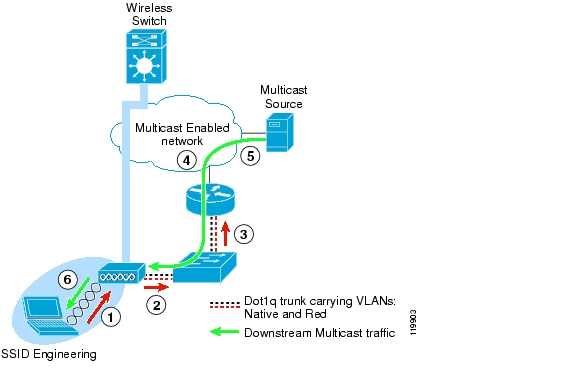
In a Cisco SWAN deployment with the WLSM, the IP multicast traffic downstream from a wired source to a wireless client is delivered outside the GRE tunnel leveraging the existing network infrastructure. This section explains what changes are required in the AP to achieve this, and the consequences from a design perspective.
Figure 10 shows how the AP processes the Internet Group Management Protocol (IGMP) join message received from the client. A similar behavior is applied to the IGMP leave message.
Figure 10 AP Processing of the IGMP Join Message
The AP has been configured with SSID = Engineering, which has been mapped to a certain network ID and also to a local VLAN: VLAN = Red. The connection between the AP and the access switch has also been configured as a 802.1q trunk. VLAN Red is carried to the switch and then to a first hop router.
The step-by-step process is as follows:
1.
2.
3.
4.
5.
6.
Note
The following additional configuration is required to enable multicast traffic with the WLSM when compared to a unicast-only solution:
•
•
You must assign an IP address to this L3 interface, and you must enable a multicast routing protocol, such as IP PIM, for example, for the router to forward the multicast traffic.
An important consequence of the multicast implementation with the WLSM, and in particular the fact that the traffic is delivered outside the tunnel, is that wireless multicast traffic cannot take advantage of the L3 seamless roaming provided by the mGRE infrastructure. As the client roams to a different AP in the same mobility group, it has to allow the time for the multicast network to reconverge before it can resume receiving the multicast traffic. This results in an interruption of traffic, and thus not in seamless roaming.
The roaming time can be improved in the following two ways:
•
•
New Concept—VLAN on the Access Point
In an AP-based WDS deployment, the AP is responsible for defining the integration between the wireless and the wired network. This integration is represented by the unique mapping between SSID and VLAN. As explained in the previous paragraph, with the switch-based WDS with the WLSM and the concept of the mobility group, this mapping is replaced by the other unique mapping between the SSID and the network ID. On the wireless side, the SSID continues to represent the method of segmenting the wireless media, but with switch-based WDS this segmentation is brought to the wired side through a GRE tunnel that is represented by the network ID. The VLAN is no longer used for this purpose. To understand the new role of the VLAN as defined on the AP, IP unicast and IP multicast traffic must be considered separately.
As previously explained in the "Traffic Flow" section, all the IP unicast traffic with the WLSM is encapsulated in GRE, and the tunnel is always sourced from the AP IP address. Thus, all the traffic is sourced from the native VLAN of the AP, where the AP IP address is defined. Unicast traffic from different SSIDs (and thus different mobility groups) is carried on different GRE tunnels using different tunnel destinations, but always sourced from the same IP address. In such a scenario, it is clear that the native VLAN is the only VLAN needed on the wired side.
This does not mean that you no longer need VLANs on the AP; the Cisco Aironet AP implementation requires that the broadcast key and security cipher be derived from the VLAN associated to a defined SSID. A unique mapping between SSID, network ID, and VLAN on the AP allows the network administrator to segment the broadcast traffic in the air and to use a different security policy for each mobility group.
Note
The situation is different for IP multicast traffic. To deliver the multicast traffic downstream from a wired source to a wireless client, a multicast VLAN must be defined not only on the AP but must also be known to the wired network. This means that the VLAN must be defined on the access switch and carried on an 802.1q trunk connection, and it also needs a L3 interface.
In summary, Cisco recommends a unique mapping between the SSID, the network ID, and the VLAN that must be configured locally to the AP. You can choose whether this VLAN must be known on the wired side of the network. This choice depends on whether or not you intend to support multicast for the mobility group.
Design Considerations
This section includes the following topics:
•
•
•
•
•
•
Scalability of the WLSM Solution
This section of the document describes how switch-based WDS achieves scalability and how it affects design of a wireless solution with the WLSM.
This section includes the following topics:
•
WLSM and Cisco Catalyst 6500 Scalability
This section includes the following topics:
•
•
WLSM and Cisco Catalyst 6500 Scalability Overview
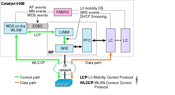
One of the most important concepts to understand about the WLSM solution and its integration with the Cisco Catalyst 6500 is the separation between control and data traffic. It is not only important to learn how packets flow through the wireless switch and thus be able to troubleshoot issues that can arise when deploying the solution, but it is also particularly important to understand how the WLSM can scale in a very large wireless implementation. By keeping the control path and the data path completely separated, the WLSM can scale to very large numbers of APs and associated clients.
The WLSM acts as the centralized WDS for the network. The WDS talks WLCCP to the APs on one side, and RADIUS to the RADIUS server on the other side. Internally, the WLSM communicates with the supervisor (and in particularly with the L3MM on the RP using L3-Mobility Control Protocol (LCP). WDS is also responsible for RM aggregation and reporting to the CiscoWorks WLSE. All this traffic is defined as control path and serves a different functionality, as described in the following:
•
–
–
–
–
–
–
•
•
Note
All the control traffic goes through the WLSM blade, and this is the only traffic that goes through the blade.
Data traffic, defined as the traffic to and from the wireless clients, never goes through the blade. All data traffic uses the switching capabilities of the Sup720 and its distributed forwarding architecture, which delivers 400 million packets per second. 802.11g or 802.11a APs can carry an average of 25 Mbps of real data traffic each. Considering an enterprise campus deployment with a large number of clients and hundreds of APs, it is very easy to reach an aggregated traffic of gigabits per second that arrives at the supervisor through the mGRE tunnel interfaces. For this solution to scale to those numbers, it is vital to have hardware-assisted switching capabilities for wireless traffic and GRE packets in particular. The Sup720 provides this functionality.
These two different paths for control and data path are described in Figure 11 where the following abbreviations have been used:
•
•
•
Figure 11 Two Control and Data Paths
WLSM and Cisco Catalyst 6500—Scalability Numbers
As described in the previous paragraph, the scalability of a wireless deployment with the WLSM comes primarily from the following two factors:
•
•
Because of the hardware resources of the WLSM (processing power, CPU, and memory), the WLSM can support a maximum number of APs and client devices, with their associated roams per second.
The WLSM hardware architecture is based on the Komodo Plus line card and it includes the following features:
•
•
As with all hardware devices, the hardware capabilities of this blade impose a limit on the processing power of the WLSM as the WLSM manages the database of all the APs and clients registered with the WDS and supports the roaming of clients. The following roaming events and actions occur in which the WLSM WDS is involved:
1.
2.
3.
4.
5.
The WLSM must also support the wireless architecture in the case of failures; a power outage or a failure in a critical part of the network infrastructure causes all the APs and clients to register at the same time.
These and other considerations were taken into account when Cisco scalability tests were conducted to arrive at the numbers that the switch-based WDS with WLSM can support. These are also the official numbers that are supported by the Cisco Technical Assistance Center (TAC):
•
•
•
If you want to scale above these numbers, you must use a second blade. Keep in mind that the roaming domain is completely separated; there is no support for inter-WLSM roaming. If a client roams from an AP registered to WLSM-1 to another AP registered to WLSM-2, the client must go through a full 802.1X authentication and renew the IP address, because all client connections are dropped and must be re-initiated when roaming occurs between two WLSMs.
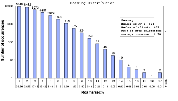
See Figure 12 to understand more of these numbers.
Figure 12 Roaming Distribution Results
Figure 12 shows the numbers of roaming events that were recorded at one university during a normal day of operation. The diagram shows for each event the corresponding number of occurrences for this event that happened, identified by the "number of roams/sec". For example, you can see that during the whole day the "1 roam/sec" was recorded 9510 times. The event "27 roams/sec" happened just twice. The average number of roams/sec was 1.5. This means that the number of roams in this example can be easily supported by the WLSM within its maximum limits.
If 20 roams/sec is exceeded at any point in time when using the WLSM, the expected behavior (which has not been tested) is for some of the wireless clients to experience a longer than usual roaming time. This means that under these stressed conditions, the advertised roaming time for FSR (<100 ms) is not guaranteed. However, it is expected that the client should still be able to roam and keep the same IP address without having to re-authenticate.
ACS Scalability
The AAA server scalability plays an important role in an 802.1X deployment. In particular, for a large wireless or wired 802.1X implementation, the AAA server can be a bottleneck if the solution is not designed properly. All the AAA authentication traffic must go through the server, and it is important to design and configure the AAA correctly to meet network needs. In case of a power outage or network failure, all the clients try to authenticate at the same time, which can easily overload the AAA server. This section describes the Cisco Secure Access Control Server (ACS), but similar consideration can be made for any other server used as the RADIUS server.
The number of authentications per second (both worst case and average scenarios) must be considered when assessing the appropriate scalability and availability for the AAA server. These numbers change with the type of EAP protocol being used. For example, Cisco Secure ACS with LEAP authentication has been tested to perform 40-60 authentications per second. When you consider other EAP types such as PEAP and EAP-TLS, then the number is likely to decrease, given the increased computation requirements of public key infrastructure (PKI) infrastructure over LEAP. Though formal testing on Cisco Secure ACS using EAP-TLS has not been performed, preliminary testing indicates a performance reduction of 20-30 percent in the number of authentications per second compared to LEAP.
Ideally, considering LEAP and 6000 clients, it takes 150 seconds to authenticate all the users if you assume the worst case scenario of 40 authentications per second. If the server receives more requests than it can manage, it immediately sends an Accept-Deny message back to the NAS and the authentication fails.
To avoid overloading the Cisco Secure ACS server and slowing down the performance of the network, a solution is needed to load balance the AAA requests across multiple servers. Cisco Secure ACS does not provide any clustering solution in which you can have multiple active servers and other servers used as backup. A load balancing solution must be implemented to redistribute all the RADIUS requests from the clients across different servers.
In a wireless architecture with the WLSM, the blade acts as an NAS for all the registered clients by relaying all the AAA requests from all the APs and mobile nodes to the RADIUS server. All the RADIUS messages carrying the EAP information are generated by the same IP address (the physical IP address of the blade), and using the same UDP ports. A load balancing solution must go deeper into the RADIUS packet to find information that is unique to each AAA request and thus can be used to load balance the traffic across multiple servers.
A possible solution is for the load balancer to examine the RADIUS headers and load balance based on Calling-Station-ID. The Calling-Station-ID in this case is the MAC address of the client. The server load balancing Cisco IOS code, starting from Release12.1E, supports this type of functionality. Following is a sample configuration for the implementation of server load balancing based on Calling-Station-ID:
ip slb serverfarm ACS-SLBnat serverreal 10.245.1.2 <<< Real Radius Server's IP Addressinservice!real 10.245.1.3 <<< Real Radius Server's IP Addressinservice!ip slb vserver Radius_AUTHvirtual 10.1.1.4 udp 1812 service radius <<< Radius Server's Virtual IP Addressserverfarm ACS-SLBsticky radius calling-station-id group 1sticky radius framed-ip group 1inservice!ip slb vserver Radius_ACCTvirtual 148.1.1.4 udp 1813 service radiusserverfarm ACS-SLBsticky radius calling-station-id group 1sticky radius framed-ip group 1inserviceCurrently, other platforms such as the Content Service Module do not support the ability to load balance based on parameters such as Calling-Station-ID.
AP-based WDS and Switch-based WDS—Can They Coexist?
With the introduction of the WLSM, Cisco SWAN provides the possibility for WDS functionality to be switch-based or AP-based, depending on the scalability requirements. In the first scenario, as we have discussed, the WDS runs on the WLSM blade in the Catalyst 6500, is usually placed in a centralized position in the network, and serves up to 300 APs in a roaming domain with 6000 associated clients. In the second scenario, the WDS is run on one of the APs, serving a maximum of 60 APs located in the same subnet.
The Cisco IOS Software release12.2.(15)XR provides the access point code to support switch-based WDS. This code allows the administrator to specify one WDS IP address for access points. This means that the AP is able to register only one WDS in the network for all the SSIDs where the WDS functionality is needed. As a consequence, when switch-based WDS is used, it is not possible to configure the AP in such a way that it falls back to an AP-based WDS solution when the switch-based WDS with the WLSM is not available. Using a combined switch-based WDS and AP-based WDS is not recommended in any case.
With the switch-based WDS and the WLSM, the AP sends all client traffic into GRE tunnels that source it from the AP native VLAN. It is easy to identify this traffic and control it, and unless multicast is configured, the connection to the switch is not a 802.1q trunk. If the WLSM fails, the AP starts bridging the traffic. The administrator loses control of the traffic and all the QoS and security policies must change to adapt to the new network configuration.
RADIUS-based Dynamic Mobility Group Assignment
As discussed previously, Cisco recommends mapping each SSID/network_ID to a unique VLAN that is locally defined on the AP. This VLAN allows the network administrator to define different security policies (802.11 encryption/authentication methods) for each mobility group.
The IT administrator may wish to assign the same 802.1X and encryption mechanisms for WLAN user access belonging to different mobility groups. In this scenario, the IT administrator may also consider imposing RADIUS-based mobility group access control, to ensure that the users are assigned to the correct mobility group.
For example, if the WLAN is set up such that all SSIDs use 802.1X and similar encryption mechanisms for WLAN user access, then a user can hop from one mobility group to another by simply changing the SSID and successfully authenticating to the AP using 802.1X. This may not be preferred if the WLAN user must be confined to a particular mobility group where certain security or QoS policies apply.
The ideal solution to this situation is to dynamically assign the user to the mobility group by providing the correct network ID after successful 802.1X authentication by the client. In the current RADIUS and WLSM release, RADIUS-based dynamic network ID assignment is not supported. A temporary solution is to use the RADIUS-based VLAN access control currently available in the AP and WDS code. There are two different ways to implement RADIUS-based mobility group access control features, as described in the next paragraphs.
The first method is to use RADIUS-based SSID access control. After successful 802.1X or MAC address authentication, the RADIUS server passes back the allowed SSID list for the WLAN user to the AP. If the user used an SSID on the allowed SSID list, then the user is allowed to associate to the WLAN. Otherwise, the user is disassociated from the AP.
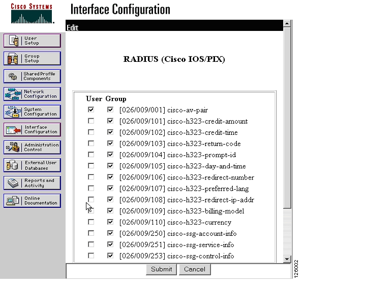
To configure this option, you simply need to program the Cisco Secure ACS server to pass back to the access point the cisco-av-pair with the SSID setting assigned to the user, using the following steps:
Step 1
Figure 13 Interface Configuration
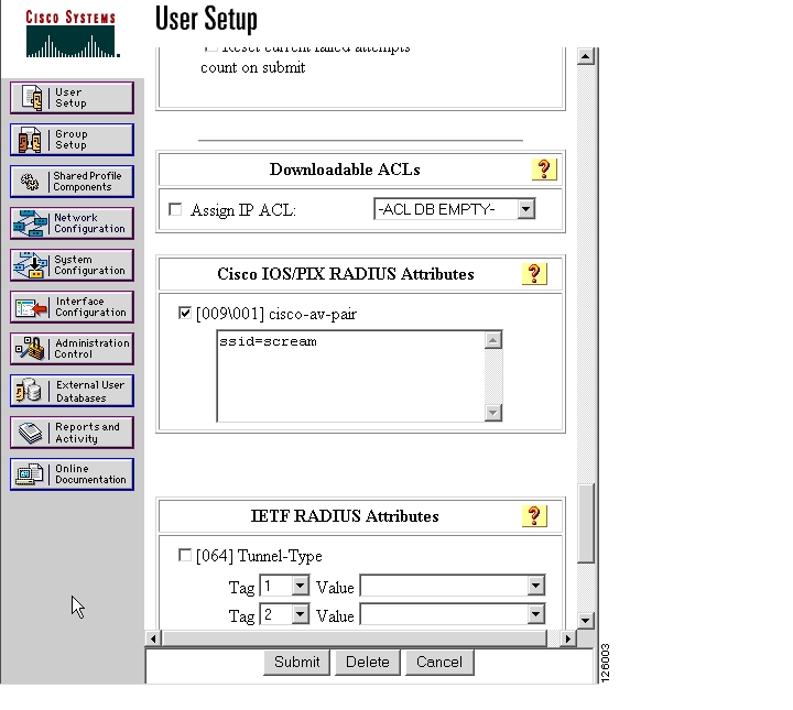
Step 2
ssid=<name>Be careful not to add any additional spaces.
Figure 14 User Setup
The second option is to use RADIUS-based VLAN assignment. After successful 802.1X or MAC address authentication, the RADIUS server assigns the user to a predetermined VLAN-ID. The SSID used for WLAN access does not matter because the user is always assigned to this predetermined VLAN-ID. The AP uses the VLAN internally to assign the user to the corresponding mobility group.
For this second option, consider an example of RADIUS-based VLAN assignment with related configuration. Both "Engineering" and "Marketing" mobility groups are configured to allow only 802.1X authentication (LEAP, EAP-TLS, PEAP, and so on) and to use the same cipher method, Cisco Temporal Key Integrity Protocol (TKIP) or WPA TKIP. On the AP, the mobility groups have the following configuration (only the interesting configuration is shown):
interface Dot11Radio0!encryption vlan 2 mode ciphers ckip!encryption vlan 7 mode ciphers ckip!ssid engineeringvlan 7authentication openauthentication network-eap eap_methodsauthentication key-management cckmmobility network-id 173!ssid marketingvlan 2authentication openauthentication network-eap eap_methodsauthentication key-management cckmmobility network-id 172As shown above, the SSIDs are configured with the same parameters except the network ID and VLAN. Following is the corresponding configuration on the supervisor:
interface Tunnel172description to_wireless_marketingip address 172.16.1.1 255.255.255.0ip helper-address 10.1.1.11no ip redirectsip dhcp snooping packetstunnel source Loopback200tunnel mode gre multipointmobility network-id 172interface Tunnel173description to_wireless_engineeringip address 173.32.1.1 255.255.255.0ip helper-address 10.1.1.11no ip redirectsip dhcp snooping packetstunnel source Loopback202tunnel mode gre multipointmobility network-id 173On the Cisco Secure ACS, two users are defined: John from Marketing is going to be assigned to VLAN 2, and Dave from Engineering is going to be assigned to VLAN 7. This is done by configuring the following user RADIUS attributes:
•
•
•
You first must enable the setting of the RADIUS attributes on a user basis, as in the following procedure,
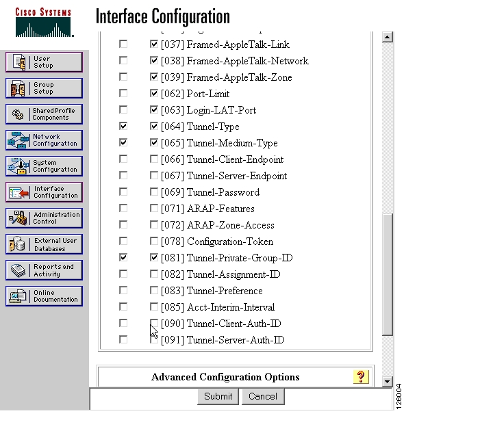
Step 1
Figure 15 Interface Configuration
Step 2
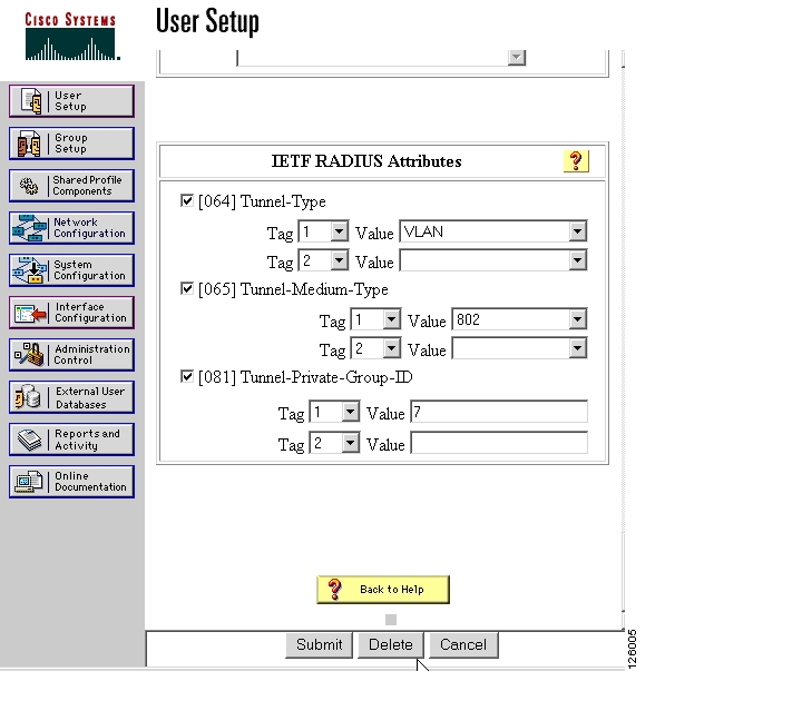
For example, see Figure 16.
Figure 16 User Setup
If Dave from Engineering uses the "marketing" SSID to gain access to the wireless LAN, then after authentication, the RADIUS server sends back VLAN-ID 7, which corresponds to the correct mobility group to which the user belongs. The AP uses this information to assign Dave to the Engineering mobility group and Dave receives a DHCP address, in the subnet 173.32.1.x/24 in this example.
Using this method, a user is mapped to a fixed wired VLAN, and thus a mobility group, throughout an enterprise network.
IP Addressing Scheme Recommendations
This section provides some general guidelines on how to design the IP addressing scheme for a wireless deployment with the WLSM to minimize the number of addresses needed for the solution, and to provide a seamless integration into the existing IP infrastructure. This section includes the following topics:
•
•
Assigning IP Addresses to the Supervisor Interfaces and to the WLSM
A VLAN must be assigned to the blade for the WLSM to communicate to the rest of the network. As described in [1], you achieve this by entering the following command in Sup720 global configuration mode:
wlan module <slot number> allowed-vlan <VLAN number>The WLSM needs an IP address and a default gateway on this VLAN/subnet. The VLAN must be defined locally from the supervisor pool of available VLANs, but the corresponding VLAN interface can be configured on any box where that VLAN is terminated. Cisco recommends choosing the WLSM VLAN and configuring the VLAN interface on the same box where the blade is allocated. There are many reasons to do this, including the following:
•
•
•
•
When deciding on the IP address and mask to assign to the VLAN interface and to the WLSM itself, it is important to consider WLSM redundancy. As explained subsequently in the "Implementing Redundancy" section, a Hot Standby Routing Protocol (HSRP)-like redundancy implementation is available for the WLSM. Given the HSRP constraints, the active and standby WLSM and the corresponding VLAN interfaces must be on the same subnet, and the VLAN must be shared between the two supervisors. This means that five IP addresses are needed on that subnet: two for the WLSMs, two for the VLAN interfaces, and one for the virtual IP (VIP) address.
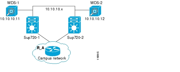
To minimize the IP addressing used, a subnet mask of 255.255.255.248 (or /29) is recommended. The subnet can be chosen from the ones available on the local supervisor. For example, the configuration of one of the two wireless switches can be the following (WLAN-1 configuration):
wlan vlan 10standby address 10.10.10.10ip add 10.10.10.11 255.255.255.248gateway 10.10.10.9adminThe following is an example of Sup720-1 configuration:
wlan module 3 allowed-vlan 10!interface vlan 10ip address 10.10.10.9 255.255.255.248Now consider the IP address to assign to the mobility group and the corresponding GRE tunnel interface, and thus the subnet or subnets where the wireless clients will reside. In this case, you have the following two options:
•
•
In the first case, you need only to configure the GRE tunnel interface that identifies the mobility group with an IP address and to dimension the subnet mask to include all the wireless hosts. One single mobility group can serve all the supported wireless clients for a maximum of 6000 users in the same subnet. In this case, a mask of 255.255.224.0 or /19 is needed. If the mobility group is untrusted, which means that only DHCP clients are allowed to connect, and assuming that the DHCP server is not local to the Cisco IOS, then the following additional configuration for DHCP is needed:
•
•
If the administrator does not want to change the previously assigned address ranges of the wireless users, it is possible to assign multiple subnets to the same mobility group. To do this, you can assign multiple secondary IP addresses to the GRE tunnel interface. If you are considering untrusted mobility networks, you must be aware of an additional configuration and limitation that goes with it. For the supervisor to be able to relay DHCP requests from multiple IP secondary addresses, you must enable the DHCP smart relay feature by issuing the following global configuration command:
ip dhcp smart-relayThis command instructs the Cisco IOS to consider the secondary addresses when receiving requests on one interface configured with ip helper-address. For example, assume the following tunnel interface configuration:
interface Tunnel1description to_Internal_employeesip address 172.28.1.1 255.255.255.0ip helper-address 10.1.1.11ip address 172.28.2.1 255.255.255.0 secondaryip address 172.28.3.1 255.255.255.0 secondary<snip>In this case, the supervisor, when receiving a DHCP request on Tunnel 1 interface, relays the request to the configured DHCP server using the primary address in the relay field. The clients in this example are assigned an address in the subnet network 172.28.1.0.
The DHCP relay agent continues to use the primary address until depletion of the primary DHCP pool or DHCP server timeout. After three request attempts and no response, the relay agent automatically starts forwarding the DHCP requests with the first secondary address configured. In this example, the clients are assigned an address in subnet 172.28.2.0. The DHCP smart relay feature supports a maximum of two secondary IP addresses.
Finally, you must consider how to select the IP address to be assigned to a mobility group. The subnets you assign to the wireless users must be advertised in the routing table if you want the mobile users to be reached by the rest of the network. This means that if you are performing summarization on the distribution layer switch where the tunnel interface is configured, Cisco recommends choosing a subnet in the summary block assigned to that switch. In this way, you do not increase the numbers of routes sent to the core upstream routers.
Assigning VLAN and IP Addresses to the AP and First Hop Router
All the unicast traffic originated from the AP is sourced from the AP IP address and is thus received by the switch on the AP native VLAN. When deciding the VLAN and IP address to assign to the AP, Cisco recommends that you choose a VLAN/subnet that is not shared by any other traffic on the access switch. There are many reasons to do this, including the following:
•
•
•
For the subnet mask, only two IP addresses are needed on that AP subnet: the IP address of the Bridge Virtual Interface (BVI) of the AP, and the IP address of the first hop router where that subnet is terminated. You need only a 255.255.255.252 (or /30) subnet.
You must take a different approach when implementing multicast. As explained earlier, for multicast to work, you must do the following:
•
•
•
•
When assigning the IP address to the first hop router multicast interface, the only requirement is that the IP address be routable, because it has to receive the client IGMP join message and build the PIM multicast tree. No other devices must be on that subnet; a /32 subnet mask can be used to save addressing space. The Cisco IOS does not let you configure a /32 address unless the interface is a loopback. Cisco then recommends using a 255.255.255.252 (or /30) mask when configuring the IP address of the L3 multicast interface.
GRE and Issues with Fragmentation
This section introduces the issues that may arise in your network after the WLSM solution is in place. All the packets from the AP to the supervisor with the WLSM are GRE-encapsulated; each packet has an extra 24 bytes that are added to the original payload. With the default IP maximum transfer unit (MTU) over Ethernet being 1500 bytes, this increases the chances of fragmentation, especially for big packets.
This section includes the following topics:
•
•
Fragmentation and Supervisor 720
Both the AP and the Catalyst 6500 do fragmentation and reassembly in software, which may or may not affect the performance of the box, depending on the traffic load.
Because of a hardware buffer space limitation and the fact that the Sup720 performs GRE packet decapsulation in hardware, received GRE fragments may not be correctly reassembled by the Sup720 if the GRE packets arrive in fragments. This is because the Sup720 must first reassemble the fragments before it is able to take off the GRE header. Because buffer space is required, but not available to storethe fragments, the Sup720 may not correctly reassemble the GRE fragments.
To minimize the effects of this situation, efforts should be made to prevent the Sup720 from receiving fragments of GRE packets. If fragmentation is needed, the fragmentation must be performed on the original packet before the GRE encapsulation, given the size of the packets and the extra 24 bytes of the GRE encapsulation. When this is done, the supervisor receives normal GRE packets and the decapsulation is successfully completed in hardware. The decapsulated packets are then switched in hardware, ignoring the fact that they are IP fragments, and the packets are reassembled by the end station.
To achieve this outcome, manually calculate the IP MTU of the path between the AP and the supervisor, checking all the switches, routers, and the connecting links along the path. Perform this for both the upstream (from the AP to the supervisor) and the downstream direction. After the minimum IP MTU has been determined, the supervisor GRE tunnel interface must be configured accordingly, as follows:
IP MTU of the tunnel = (IP MTU) min - 24 bytes
The configuration is needed only on the supervisor tunnel interface. After this is done, the L3MM informs the WDS, which in turn generates a WLCCP message update to the AP with the configured IP MTU value. This is done automatically, and you do not need to do any other AP configurations. By setting the IP MTU on both the APs and the tunnel interfaces of the supervisor to this value, you help to ensure that if fragmentation is needed, it is performed before encapsulating in GRE. The default IP MTU on a tunnel interface of both the AP and supervisor is 1476 bytes.
For example, if the minimum IP MTU along the path is 512 bytes, then you must set the IP MTU on the tunnel interface to be 512 - 24 = 488 bytes. Use the following interface command:
sup720(config-if)#ip mtu 488To go back to the default settings, use the no ip mtu command. To verify that the configuration works, you can use the show ip interface tunnel command on the supervisor, or use the show wlccp wds mobility command on the WLSM CLI. Following is the output of these commands:
sup720#sh ip int tunnel 172Tunnel172 is up, line protocol is upInternet address is 172.16.1.1/24Broadcast address is 255.255.255.255Address determined by non-volatile memoryMTU is 488 bytes<snip>Be careful, because the show interface tunnel command shows the L2 MTU that is not the one you have just changed with the command above. It is the IP MTU that must be changed.
Instead, see the following configuration from the WLSM CLI:
WLSM-2#sh wlccp wds moLCP link status: upHSRP state: ActiveTotal # of registered AP: 2Total # of registered MN: 2Tunnel Bindings:Network ID Tunnel IP MTU EPOC ID FLAGS========== =============== ========= ========= =====99 10.10.201.1 1476 7100 10.10.1.4 1476 3110 10.10.1.1 1476 2 T172 10.10.200.1 488 4 <<<<<<<<<<<<< MTU change173 10.10.203.1 1476 5192 10.10.202.1 1476 6
Note
GRE Tunnels and Internet Access
Although fragmentation is supported in the IP protocol, fragmented packets can cause unexpected behavior in your network.
In the scenario detailed in this paragraph, the users are not able to browse certain web pages when GRE tunnels are introduced in the path to the Internet. This issue is common to all the implementations of GRE tunnels, and not just with the WLSM. Although the WLSM may trigger the situation, it is not the cause of the situation.
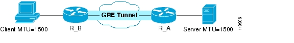
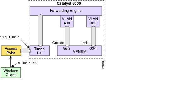
Consider the simple network shown in Figure 17.
Figure 17 Sample Network with GRE Tunnel
The client wants to access a page on the Internet, so it establishes a TCP session with the web server. During this process, the client and web server announce their maximum segment size (MSS), indicating to each other that they can accept TCP segments up to this size. After receiving the MSS option, each device calculates the size of the segment that can be sent. This is called the Send Max Segment Size (SMSS), and it equals the smaller of the two MSSes.
Note
As an example, assume that the web server in Figure 17 determines that it can send packets up to 1500 bytes in length. It therefore sends a 1500-byte packet to the client, and in the IP header it sets the "don't fragment" (DF) bit. When the packet arrives at R_A, the router tries encapsulating it into the tunnel packet. In the case of the GRE tunnel interface, the IP MTU is 24 bytes less than the IP MTU of the real outgoing interface. For an Ethernet outgoing interface, that means the IP MTU on the tunnel interface would be 1500 minus 24, or 1476 bytes. R_A is trying to send a 1500-byte IP packet into a 1476-byte IP MTU interface. Because this is not possible, R_A must fragment the packet.
However, remember that the packet received by R_A has the DF bit set. Therefore, R_A cannot fragment the packet, and instead, it must instruct the web server to send smaller packets. It does this by sending an Internet Control Message Protocol (ICMP) type 3 (code 4) or "ip unreachable" message. This ICMP packet contains the correct MTU to be used by the web server, which should receive this message and adjust the packet size accordingly.
However, it may well happen that this message is filtered somewhere in the network between the R_A and the web server. In this case, the server never receives the ICMP message and therefore never changes its MTU size. The result is that the client is not able to browse certain web pages on that server.
A possible solution to this situation is to ensure that the ICMP messages are not filtered. Start by enabling "ip unreachable" on the router interface where the fragmentation would happen. In a WSLM implementation, this means that you must enable this command on the tunnel interface. Unfortunately, there might be cases in which the ICMP messages are filtered in parts of the network that are not under your control. In that case, use one the following alternatives:
•
•
Note
•
•
Note
Design Limitations and Caveats
This section lists some important caveats and limitations that must be considered when designing a WLAN solution with the WLSM. It includes the following topics:
•
•
EAP-Type Support for CCKM
Currently, LEAP and EAP-FAST are the only two EAP types that are supported in terms of CCKM and thus the only two 802.1X authentication protocols that support Fast Secure Roaming. Cisco SWAN and WLSM support all the other EAP types (PEAP, EAP-TLS, PEAP-GTC, and so on), but for these protocols, the roaming time is not as fast as the CCKM-enabled ones. This is because without CCKM, there is no caching of user credential in the WDS. This means that every time the client roams from one access point to another, a full authentication is needed with the RADIUS server. It is still a Layer 3 roaming, so the client keeps the IP address, but the roaming time is not guaranteed to be under 100 ms.
Wireless and Wired Client on the Same Subnet
The architecture of the WLSM does not allow a wireless client to share the same subnet with a wired device or appliance. In other words, the two devices cannot be connected at Layer 2. For example, this prevents any application that relies on L2 broadcast from functioning correctly. This is because the wireless subnet is implemented by including all the wireless clients in the same mobility group and the corresponding tunnel interface on the Sup720 where it is terminated. The GRE tunnel interface is an L3 virtual interface that cannot be assigned to a wired VLAN.
NAT Caveat
Network Address Translation (NAT) allows private addresses to be hidden from the rest of the network. Some protocols such as H.323, Skinny, and so on, carry IP addresses information in the payload. In this case, the network device performing the NAT translation must look into the payload and change the required fields. To do this, the NAT device needs a fixup, which is software that knows how to inspect the payload of the specific protocol.
If NAT is involved in the design of a wireless network with WLSM implementation, consider the following points:
•
•
•
Usually this limitation does not create many problems for the network design because all wireless infrastructure devices are part of what is considered the internal network from a NAT perspective, and the communication does not involve IP address translations.
Multiple WDS per AP
It is not currently possible to specify different WDS for different SSIDs on one single AP. As mentioned previously, only one IP address can be specified on the APs, which means that all the SSIDs defined on the AP refer to the same WDS, whether it is a switch-based or an AP-based WDS.
Troubleshooting Commands—Caveats
There are some current limitations about some commands that can be used to troubleshoot an implementation of the WLSM. These limitations exist because of the lack of rewrite engine functionality on the WLSM blade, and major changes in the hardware architecture would be needed to overcome them. These limitations are the following:
•
•
Implementation Details
This section describes how to implement the various aspects of the WLSM solution, and includes the following topics:
•
•
•
Implementing Quality of Service
This section describes the end-to-end quality of service (QoS) solution for the WLAN deployment using the WLSM. After an overview of the pre-WLSM AP QoS implementation, this section examines the changes required to the AP QoS implementation and the configuration required on both the AP and the Catalyst 6500 where the WLSM is inserted. The traffic from the AP to the rest of the network is considered upstream traffic, and traffic in the opposite direction is considered downstream traffic.
This section includes the following topics:
•
AP QoS (pre-WLSM)
This section includes the following topics:
•
•
•
AP QoS Overview
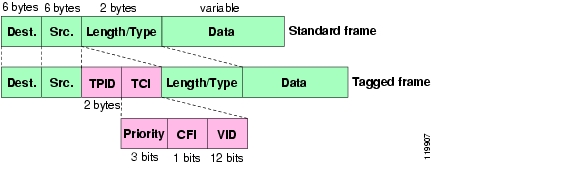
From a networking perspective, the Cisco AP is a Layer 2 device that acts like a bridge. In relation to QoS, the AP deals internally only with the Layer 2 information, namely the class of service (CoS) value, even if the classification and marking can be done based on L3 or L4 information. The CoS is 3 bits of QoS information contained in the priority field of the 802.1q tagged frame, as shown in Figure 18.
Figure 18 QoS Information—CoS
In AP-based WDS, before the introduction of the WLSM, the AP received the CoS information from the incoming Ethernet packets by looking at the 802.1p value in the 802.1q tag of the Ethernet frame. This required a trunking configuration between the AP and the access switch.
The Cisco AP is compatible with the 802.11e standard for wireless QoS, and the CoS values are internally mapped to the corresponding 802.11e classes as shown in Table 1.
Table 1 CoS Values Mapped to 802.11e Classes
0
1-Best effort
1,2
0-Background
3,4,5
2-Video
6,7
3-Voice
QoS Implementation for Voice Traffic
The Cisco AP implements the IEEE CoS values that require voice to be marked with CoS = 6. In all the other Cisco products that follow the Cisco Architecture for Voice, Video and Integrated Data (AVVID) recommendation, the CoS value for voice is the IETF value (CoS = 5).
For the AP to be compliant with the AVVID recommendation, an internal mapping is automatically performed from CoS = 5 to CoS = 6 for downstream traffic. The AP remarks the received traffic that has CoS = 5 with CoS= 6 before processing it internally.
No mapping happens for upstream traffic, so it is necessary for the access switch to remark the CoS received from the AP to the desired value. To do this, you can use the following command in global configuration mode:
mls qos map cos-dscp 0 8 16 26 32 46 46 56This mls command remarks all the incoming frames with the Differentiated Services Code Point (DSCP) value corresponding to CoS = 5. The internal QoS computation of the switch, which is based on the DSCP value, is performed as if the frame was received with an actual CoS = 5 in the 802.1p field.
Note
AP QoS Classification
Internally, the AP classifies traffic based on the following filters, in order of priority:
1.
2.
3.
4.
AP QoS Marking
For each of the classification methods, the AP can set only the Layer 2 CoS value. When considering a MQC implementation, remember that the set ip precedence command in the policy map configuration is accepted by the CLI but not enforced by the AP, because this is Layer 3 QoS information.
MQC Implementation on the AP
When there is one MQC policy configured on the radio interface and another on the FastEthernet interface, and both are defined for the same traffic and applied to the same direction (both downstream or both upstream), only the first policy is considered and the other is ignored. For example, configure a policy to mark upstream video traffic with CoS 4 and apply it on the radio interface; then configure another policy for the same traffic to be marked with CoS 3 and apply it to the FastEthernet interface. Only the first policy is considered by the AP, and the traffic goes out from the AP with a CoS of 4.
AP QoS Interface Transmit Queues
The AP has a total of five transmit queues on the radio interface and one queue on the FastEthernet interface. On the radio interface, there are four queues for unicast traffic and one queue for broadcast and multicast traffic. The four unicast queues are mapped 1:1 to the four different values of the 802.11 Enhanced Distributed Coordination Function (eDCF) classes. An explanation of how eDCF works is beyond the scope of this document, but keep in mind that eDCF is the way the AP implements QoS in the air. Each queue has a corresponding value of backoff time (based on a specific contention window value) that determines the priority for the traffic to access the media.
The queuing implementation on the AP is different from any other Cisco switches or routers. In the wireless world, QoS is statistical, which means that even the highest queue does not have a true priority versus the other queues. In other words, the traffic in the highest queues has just a higher probability of being sent into the air than the traffic in the lower queues. From a queuing implementation perspective, this means that the access to the media is actually first in first out (FIFO) and the different values of backoff time assigned to each queue determine the way traffic is sent to the FIFO queue to be sent into the air.
For example, when the first data frame arrives at the radio interface, it is sent to the corresponding queue based on its classification. This means that the frame is going to be assigned a certain value of eDCF contention window (CW). Next, a backoff time is calculated based on the CW value, the backoff time starts to be decremented. When the backoff time expires, the AP makes an attempt to send the frame. Now assume that a voice frame arrives with a higher priority. Based on its priority, it gets assigned a higher queue, which means a lower backoff time because of its CoS value and eDCF class that statistically expires before the data frame. So, the voice frame has more chances to be sent first, but this is not guaranteed.
QoS Implementation with the WLSM
This section includes the following topics:
•
•
•
•
QoS Implementation with the WLSM Overview
When designing a QoS end-to-end solution with the WLSM, there are a few things to consider. First, there is no change in the way the AP implements QoS in the air; eDCF is still the way to provide different priority when accessing the wireless media. All the changes required are on the wired side.
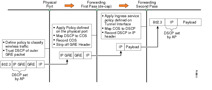
As explained in the "Traffic Flow" section, with the WLSM, all unicast traffic, both upstream and downstream, is GRE-encapsulated and is sent and received on the AP native VLAN. This means that the AP can no longer rely on the CoS information in the Ethernet frame for setting or receiving QoS parameters. The traffic on the native VLAN, by definition, is untagged, which means that there is no 802.1q tag and thus no CoS value.
To support end-to-end QoS, the AP must be able to set and understand the L3 QoS information contained in the IP header, which is basically the IP precedence or IP DSCP values. Remember that internally, the AP understands only L2 CoS values, so a mapping is needed between the L3 QoS information and the corresponding L2 value.
AP QoS Implementation with the WLSM
To better understand what changes are required for the QoS implementation on the AP, consider the three different internal software processes involved in processing a frame: the AP radio interface, the AP forwarding process, and the AP FastEthernet process. Consider also separately the downstream and upstream traffic.
Downstream traffic—This scenario assumes that downstream traffic comes to the AP with a DSCP value set in the external IP GRE header, as shown in Figure 19.
Figure 19 Downstream Traffic
The AP must be capable of recording this Layer 3 DSCP value and mapping it internally to L2 CoS information.
The following sequence takes place:
1.
2.
3.
4.
If the packet received has no L3 QoS information at this point, then after the GRE header has been stripped off, the QoS implementation follows the same rules described in the overview session in terms of classification, marking, and queuing.
Now consider one of these examples in which the AP receives traffic with no DSCP value set, and you want to assign a CoS = 4 to the traffic destined to a specific wireless client.
The following steps are required.
Step 1
Figure 20 CoS Assignment
Step 2
Upstream traffic— the next scenario examines the implementation of QoS on the AP for upstream traffic. The challenges are the same as described above; you need a mechanism to map the L2 information to the L3 information. In the WLSM solution, this is done automatically by the AP, as shown in Figure 21.
Figure 21 Upstream Traffic
The following sequence achieves this result:
1.
2.
3.
4.
The table used by the AP for the CoS-to-DSCP mapping is not configurable by the user. (See Table 2.)
Note
In the following example, the following steps configure a policy to mark traffic coming from a specified IP address.
Step 1
Figure 22 Creating a Filter
Step 2
Figure 23 Creating a Policy Map
Step 3
Figure 24 Applying the MQC Policy
Step 4
Figure 25 Verifying the Mapping
Catalyst 6500 QoS Implementation with the WLSM
One of the main advantages of the Cisco SWAN architecture with the WLSM is that all the wireless traffic from a specific mobility group has one single point of ingress/egress to the wired network. This makes it very easy to apply security or QoS policy to this traffic by simply configuring the policy on the GRE tunnel interface.
In particular, MQC is used on the Catalyst 6500 to implement QoS. In the case of wireless traffic, this implies applying the service policy command directly on the mGRE tunnel interface.
Note
First consider upstream traffic from the wireless clients to the rest of the network. When traffic is received from the AP, there is no automatic mapping of the DSCP value in the external IP GRE header to the internal, original IP header. This is something that must be enforced for an end-to-end implementation of QoS.
To copy the DSCP value settings from the GRE header to the inner IP header, you must follow a required procedure, given the hardware implementation of GRE tunnels. The supervisor must be instructed to trust the received DSCP value on the GRE-encapsulated packet; then it must record the corresponding CoS value (which is used internally), and finally to copy this value to the outgoing decapsulated packets.
The step-by-step procedure, as shown in Figure 26, is the following:
Step 1
Step 2
Step 3
Step 4
Figure 26 Copying the DSCP Value Settings
The following sample configuration achieves the purpose described above. In this example, the wireless traffic destined to a certain mobility group has been selected for QoS support. This means that all the GRE traffic destined to the loopback interface corresponding to the mobility group must be matched and marked accordingly.
Assuming that Gigabit Ethernet 3/1 is the physical interface on the Catalyst 6500 facing the APs, this is the configuration you need for trusting the received DSCP value:
access-list 101 permit gre any host 10.10.100.1!class-map match-all match-wirelessmatch access-group 101!policy-map trust-wirelessclass match-wirelesstrust DSCP!interface loopback 0descriptions tunnel_source_for_mobility_101ip address 10.10.100.1!int GigabitEthernet 3/1service-policy input trust-wirelessFollowing is the configuration to map the internal recorded CoS value to the DSCP value in the original packet:
class-map match-all copy-DSCPmatch any!policy-map upstreamclass copy-DSCPtrust COS!interface Tunnel 101ip address 101.1.1.1tunnel source Loopback0tunnel mode gre multipointmobility network-id 101service-policy input upstreamFor downstream traffic, the DSCP value in the original IP header is automatically copied to the outer GRE header when the packet is encapsulated and sent to the AP. All you need to do is trust the DSCP value on the ingress physical interface towards the source (all interfaces are untrusted by default).
Catalyst 6500 QoS Implementation with the WLSM and PFC-3A
At present, the hardware design of the PFC-3A prevents any QoS configuration from being applied on a GRE tunnel interface. The situation is solved with the new generation of application-specific integrated circuits (ASICs) being shipped with the PFC-B series and higher.
Given the large customer base that may still use Sup720 with PFC-3A, in this paragraph a limited solution to implement QoS for wireless traffic on the Sup720 is described. For the upstream traffic, given the current implementation of QoS on GRE tunnels described in the previous paragraph, it is not possible for PFC3A to copy the outer QoS marking to the inner packet. For this reason, the suggested implementation considers only traffic downstream when QoS marking is originated on the supervisor.
Wireless traffic belonging to the mobility group is uniquely characterized by the source of the mGRE tunnel interface that defines the mobility group. This IP address is the source of the GRE tunnel on the supervisor side (the IP address of the AP is always on the AP side, no matter what mobility group you are considering). Considering this, a possible solution for implementing QoS for wireless traffic is to implement a QoS per mobility group. The traffic of the specific mobility group can be classified based on the tunnel source interface and marked accordingly. In this case, the QoS policy is applied on the physical interfaces that send the GRE traffic towards the AP.
In the following example, the voice traffic sent from the wired network to a wireless phone is prioritized. The mobility group for voice traffic is defined by configuring an mGRE tunnel interface on the Sup720 with the following configuration:
interface Loopback200description tunnel_sourceip address 10.10.200.1 255.255.255.0interface Tunnel172description Voice_mobility_groupip address 172.16.1.2 255.255.255.0ip helper-address 10.1.1.11tunnel source Loopback200tunnel mode gre multipointmobility network-id 172The GRE traffic going towards the wireless client is marked with DSCP = EF. In this way, the traffic can be prioritized across the IP network located between the Catalyst 6500 and the AP where the wireless phone is associated. Assuming the interface FastEthernet 1/48 is the one facing the AP, use the following configuration:
class-map match-al match-voicematch access-group 101!policy-map mark-voiceclass match-voiceset dscp EF!interface FastEthernet 1/48description to_wirelessservice-policy output mark-voice!access-list 101 permit gre host 10.10.200.1 anyAll the GRE packets carrying voice traffic are marked with the desired DSCP.
As mentioned before, this is a limited solution because you can only mark the traffic belonging to a mobility group, and you can not apply different policies within the group itself. This assumes that you can separate different types of traffic with different QoS policies into different mobility groups.
Implementing Redundancy
This section describes the two different types of redundancies in your network that you can use when considering a Cisco SWAN implementation with the WLSM. It includes the following topics:
•
•
Leveraging Intra-Chassis Redundancy
With the WLSM release 1.1(1) of WLSM software, only one WLSM module is supported in each Catalyst 6500 chassis.
Because the L3MM subsystem and GRE tunnels are run from the supervisor, these elements benefit from supervisor failover. There are three forms of redundancy provided by the supervisor engine: Route Processor Redundancy (RPR), Route Processor Redundancy Plus (RPR+), and Stateful Switchover (SSO). The main characteristics of RPR+ and SSO are summarized as follows:
•
–
–
–
–
•
–
–
–
–
–
SSO is the recommended option because it provides a stateful solution. To achieve no traffic interruption after supervisor failover, you need to enable the Nonstop Forwarding (NSF) feature in your network; otherwise the routing neighbors of the failing supervisor detect the failover and try to reconverge.
Note
SSO is enabled by default starting from Cisco IOS release 12.2(17a) SX. The commands to enable it are as follows:
redundancymode ssomain-cpuauto-sync running-configauto-sync standardLeveraging Inter-Chassis Redundancy
This section includes the following topics:
•
•
•
•
•
Inter-Chassis Solution Overview
Currently, the only available option for providing a redundant implementation with the WLSM is an inter-chassis solution. The mechanism used is very similar to the HSRP protocol used by routers; it enables two WDS running on different blades to work together in a group to provide a virtual WDS service by sharing a virtual IP address and virtual MAC address. The virtual IP address is configured in each AP as the WDS IP address. You need to have two blades installed in two separate chassis, and an L2 connection between the two supervisors. The two WDS processes running on the WLSM blades exchange HSRP keepalives and elect the active WDS for the network. At any time, only one WDS can be in active state.
As with HRSP and routers, the switchover is not stateful. In this case, it means that the new active WDS does not have any information about the APs and mobile nodes (MNs). As a consequence, the APs and clients need to register to the new WDS before traffic can start flowing again.
There are the following two ways in which the AP detects the new active WDS and registers again:
•
•
Regarding convergence time, it takes 90 seconds for the new WDS to build the internal AP database in the worst-case scenario. The clients then need to register as well, and only at that point does the traffic flow again. In a best-case scenario, the AP sends the registration update immediately after the switchover, speeding up the reconvergence process.
Note
Description of the WLSM Failover
As mentioned previously, the WLSM uses a redundancy mechanism very similar to HSRP. However, there are some differences that are described in this section.
As with HSRP, the active and standby WDS processes exchange keepalives (every 3 seconds by default) and the standby takes over after not hearing the hello messages for a period equal to the hold time (10 seconds by default).
You can configure a "priority" under the standby configuration to influence which WDS becomes active at boot time. Differently from an HSRP implementation on routers, the priority is only considered at boot time because the WDS implementation of HSRP does not consider preemption. After the standby becomes active, it stays active even if the other WDS comes back up and has a higher priority. This was done to minimize the traffic interruption because of the WDS failover.
Configuring WLSM Failover
To configure WLSM redundancy, you need to perform the following steps.
Step 1
Step 2
Step 3
Step 4
Step 5
Table 3 shows a sample configuration.
If you assume WDS-1 to be the active WDS at one point, the tunnel interface on Sup720-2 is forced to be in down state, and the rest of the network learns about the wireless subnet through Sup720-1.
WLSM Failover—IP Addressing and Interaction with Routing Protocols
Routing protocols such as Open Shortest Path First (OSPF) and Border Gateway Protocol (BGP) calculate the router ID based on the highest IP (if no loopbacks are present) independently from the state of the interface. To avoid any router ID duplication, the recommended approach is to configure two different addresses on the tunnel interfaces for the same mobility group as shown above. The consequence of this configuration is that you need to specify two default gateways in the DHCP scope configuration. This is explained in greater detail in the "WLSM Failover—DHCP Configuration" section.
Now consider the routing of packets to the WLSM blades (this is the control traffic from the AP or the RADIUS traffic to and from the RADIUS server). The two WDS processes reside on the same subnet (10.10.10.0/24 in the above example), and they use their own physical address and not the virtual IP address to communicate with the other devices in the network.
Figure 27 shows a general scenario for this solution.
Figure 27 Routing of Packets to WLSM Blades
It is very likely that a downstream router (say R_A in this example) would have two equal cost paths in its routing table to reach each of the WLSMs. Assume that WDS-1 is the active WDS; packets destined to 10.10.10.11 are load balanced between the two available paths (the one through Sup720-1 and the one through Sup720-2). In normal operation, the packets to WDS-1 are routed unnecessarily through an extra hop through Sup720-2. Also, if the Sup720 -2 goes down, it takes time for the network to reconverge, and some packets may be lost.
To avoid this non-optimal scenario, Cisco recommends that you install on the downstream router a host route to WDS-1 pointing it to Sup720-1, and another to WDS-2 pointing it to Sup720-2.
WLSM Failover—Integration of RPR+ and SSO Switchover
This section briefly analyzes the configuration changes recommended when implementing WLSM switchover with RPR+ or SSO.
When using RPR+ as a supervisor switchover mechanism, it is better to change the default HSRP timer configuration to avoid unnecessary transition between active and standby WDS. This scenario is described in the following example.
Assume that at a certain point, WDS-2 (IP 10.10.10.12) is the active WDS and that WDS-1 (IP 10.10.10.11) is the standby. If there is a RPR+ switchover on Sup720-2, then WDS-1 stops receiving hellos from the active WDS, and after 10 seconds (the default hold timer) it transitions to active. On the other side, from the WDS-2 point of view, it is still in active state and keeps sending HSRP hellos that do not reach WDS-1.
After the Sup720-2 comes back up after the RPR+ switchover, WDS-2 starts hearing hellos from WDS-1 again. But because it is already in active state and its own IP address is higher than WDS-1, it sends a coup message to WDS-1 to regain the initial active-standby configuration.
To avoid this unnecessary transition of states, the HSRP hold time should be increased to a value higher than the RPR+ reconvergence time, and the hello timer should also be changed accordingly; for example, 20 seconds for the hello and 60 seconds for the hold time. To change the timers, use the standby <group> timers [hello] [hold] > command under the WLAN VLAN configuration mode on both the WLSM blades.
No changes are needed when using SSO switchover because the standby supervisor and the connection to the active WDS come back before the standby WDS can notice any failure in the communication.
WLSM Failover—DHCP Configuration
For the wireless client to maintain the same IP address after WDS failover, an external DHCP server is needed. You also need to consider the configuration of each DHCP client scope.
Recall from the "IP Addressing Scheme Recommendations" section that Cisco recommends configuring the two tunnel interfaces on the two supervisors with two different IP addresses (in the same subnet assigned to the mobility group). This is needed to avoid problems in dealing with some routing protocols. From a client perspective, it means that the MN has a different IP address as the default gateway depending on the WDS and supervisor with which it registered. For this to happen, the DHCP server must be configured to return both IP addresses to the client.
Note
Applying Catalyst 6500 Features to Wireless Traffic
This section includes the following topics:
•
•
Applying Catalyst 6500 Features to Wireless Traffic Overview
One of the main advantages of implementing a wireless solution with the WLSM is that you can use all the Catalyst 6500 features and apply them to wireless traffic. In this way, the wireless clients are no longer considered part of a separated network from the wired clients. They not only share the same network resources such as ACS for authentication, CiscoWorks for Management, Cisco Building Broadband Service Manager (BBSM), or Service Selection Gateway (SSG) for Guest Access, and so on, but they can also share the same security and QoS policies. With the WLSM, there is one point of ingress to the wired network for all the wireless traffic, which is the mGRE tunnel interface of the mobility group. You apply all your policies to the tunnel interface.
This section describes the different Catalyst 6500 features that can be applied on mGRE tunnels and thus on wireless traffic. For each of them, a brief description of the feature itself and its applicability for wireless is provided. The hardware acceleration and the hardware requirements are analyzed as well.
Using Access Control Lists
With Sup720, ACLs are implemented in hardware on GRE tunnels. ACLs can be used in the same way they are used for wired traffic. In this case, when applied to the mGRE tunnel interface, they affect all the wireless traffic belonging to the mobility group to which the tunnel interface belongs.
Suppose you want to limit traffic from the guest mobility group to IPSec only. In this way, the guests are only able to use the virtual private network (VPN) back to their corporate headquarters. Assuming the DHCP addresses assigned to the guests are from the subnet 172.16.1.0/24, the following might be a possible configuration:
access-list 111 permit udp 172.16.1.0 0.0.0.255 eq 500 any eq 500 ‡ allow ISAKMP!access-list 111 permit 50 172.16.1.0 0.0.0.255 any ‡ allow ESP protocol!interface Tunnel193description to_GUEST_wirelessip address 193.1.1.2 255.255.255.0ip helper-address 10.1.1.11ip dhcp snooping packetsip access-group 111 inmls ip ids capturetunnel source Loopback201tunnel mode gre multipointmobility network-id 99Using Policy-Based Routing
Policy-based routing (PBR) provides a mechanism for expressing and implementing forwarding and routing of data packets based on the policies defined by the network administrators. It provides a more flexible mechanism for routing packets through routers, complementing the existing mechanism provided by routing protocols. Another possible application of PBR is to classify traffic using ACLs and then set the IP precedence or type of service (ToS) values, thereby tagging the packets with the defined classification.
Note
In a WLSM solution, you can use PBR to route wireless traffic differently according to the mobility group to which it belongs. You might decide to segment your network is such a way that, for example, the voice traffic is directed to the voice gateway, the guest traffic is sent directly to the DMZ of a firewall, and the other traffic gains access to the internal network through a Firewall/IDS/VPN combination. This is described in Figure 28.
Figure 28 Using PBR
PBR is supported in hardware on Sup720 on GRE tunnel interfaces.
There is currently a limitation in the implementation in hardware of PBR. If the "ip next-hop" parameter specified in the route map is a GRE tunnel interface, then all the traffic is switched in software. Assume you want to transport your guest wireless traffic from the Sup720 directly to the DMZ of the firewall in the Internet edge by using GRE. All the traffic coming from the GRE tunnel interface for the mobility group "Guest" must be routed to another tunnel interface. This is feasible with PBR and very easy to implement, but in this case, because the next hop is another tunnel, the traffic is switched in software by the supervisor. In this scenario, you can consider VPN routing and forwarding (VRF) as an option.
Using SPAN, Remote SPAN, and the mls ip ids Command
Switched Port Analyzer (SPAN) is a feature in the Catalyst 6500 for sending a copy of a set of packets or a data stream to a target port in the same chassis. Its usual application is for sending a copy of the data to a network sniffer or RMON probe. Remote SPAN (RSPAN) allows you to have the target port on a separate chassis.
Note
SPAN can be configured to monitor the following:
•
•
To analyze the WLCCP and other control traffic to and from the WLSM blade, set up a SPAN session to monitor the VLAN assigned to the module. For example:
wlan module 3 allowed-vlan 10!monitor session 1 source vlan 10!monitor session 1 destination interface fas 4/3How can you use SPAN on the wireless traffic? SPAN is not supported on tunnel interfaces, and if a SPAN session is configured on the physical ports to the APs, the SPAN captures only the GRE-encapsulated packets. To capture the original wireless traffic, you need to configure the mls ip ids command on the tunnel interface. This command sets the internal capture bit so that all the ports configured to listen to this bit receive the traffic. To configure the physical port to receive the traffic, use the switchport capture command.
For example, use the following configuration to capture the internal wireless employee traffic and to send it to a network analyzer connected to the switch:
ip access-list extended capture-aclpermit ip any any!interface Tunnel11description to_Internal_employeesip address 172.28.1.1 255.255.255.0ip helper-address 10.1.1.11ip dhcp snooping packetsmls ip ids capture-acltunnel source Loopback20tunnel mode gre multipointmobility network-id 88!interface FastEthernet 4/7description to_snifferswitchport captureThese are the same commands that you use when sending traffic to an Intrusion Detection System Services Module (IDSM2). In this case, you need to replace the physical port switchport capture command with the actual configuration for the data port of the IDS module itself, as in the following:
intrusion-detection module 4 data-port 2 capture
Note
Using NetFlow
This section includes the following topics:
•
NetFlow Overview
NetFlow collects statistics on traffic that flows through the switch. NetFlow statistics are kept in the NetFlow table on the Sup720. NetFlow Data Export (NDE) is the process on the switch that allows these statistics to be exported to a collector where the statistics can be formulated into reports and charts.
For wireless traffic, you can enable NetFlow on the Catalyst 6500 where the WLSM is allocated so that you are able to collect statistics on both the GRE-encapsulated and decapsulated traffic. Packets to and from the physical interfaces still have the GRE header, and the original wireless traffic is sent or received by the tunnel interfaces.
NetFlow can be leveraged by other Catalyst 6500 features. For example, you can apply QoS policies based on flow. Later in this section, an example of how to provide user-based rate limiting on wireless traffic is provided.
Configuring NetFlow
This section provides the basic configuration for NetFlow.
Note
First, you need to enable NetFlow on the PFC if you are interested in the traffic that goes through the switch. For doing this, use the following command:
6500(config)#mls netflowNext, set the mask to the desired value (by default the mask is NULL on the Sup720, which is different from earlier hardware version of Supervisor where the mask default to "destination"):
6500(config)# mls flow ip ?destination destination flow keyworddestination-source destination-source flow keywordfull full flow keywordinterface-destination-source interface-destination-source flow keywordinterface-full interface full flow keywordsource source only flow keywordAt this point, if you want to export the NetFlow data, you need to specify the NetFlow collector:
6500(config)#ip flow-export destination 195.111.23.40 2002If desired, NetFlow can be enabled for the control traffic directed to the Multilayer Switch Feature Card (MSFC). This is done on a per-interface basis using the following interface command:
6500(config-if)#ip route-cache flowUsing NetFlow for User-Based Rate Limiting
NetFlow can be used in conjunction with QoS features to provide user-based rate limiting. This is a very powerful tool when applied to wireless traffic. For example, assume that you decide to provide wireless Internet access to your guest inside your enterprise but you want to ensure that each user does not get more than a certain bandwidth so internal resources are not compromised.
You need only to define a policy map and apply it on the tunnel interface that represents the mobility group for guest traffic. In the policy map configuration, you have to rate limit the traffic based on a source-only flow mask. This means that each source IP is considered a flow regardless of the destination of the traffic, and is policed accordingly. Following is a sample configuration in which each user is assigned a 500k bandwidth:
ip access-list extended guest-users-aclpermit ip 172.16.20.0 0.0.0.255 any!class-map guest-usersmatch access-group guest-users-acl!policy-map rate-guestsclass guest-userspolice flow mask src-only 496000 3000 conform-action transmit exceed-action drop!interface tunnel 2description to_Guestservice-policy input rate-guests
Note
Catalyst 6500 Service Module Integration
This section includes the following topics:
•
•
Catalyst 6500 Service Module Integration Overview
The WLSM represents the most recent addition to the Catalyst 6500 services module family that includes the Firewall Services Module (FWSM), the VPN Services Module (VPNSM), the SSL Services Module (SSM), and the Intrusion Detection Module (IDSM2). The introduction of the WLSM provides opportunities for wireless traffic to use the services provided by these other modules.
From a design perspective, each of the services modules demands a base set of configuration rules that need to be considered when combining multiple services modules together. This section explores how the WLSM can be integrated into the same chassis, and how it interoperates with other services modules; in particular, the FWSM, the VPNSM, and the IDSM2.
Service Module Interoperation with the WLSM
To understand how other service modules interoperate with the WLSM, you must first understand how each of the above-mentioned service modules manages data. The service modules operate in one of the two following forms (see Figure 29):
Figure 29 Service Module Operating Modes
With service modules that operate in the BITW mode, a packet must pass through the service module to be processed. The FWSM and VPNSM both operate in BITW mode. In promiscuous mode, a copy of the packet must be forwarded to the module for it to process the data. In promiscuous mode, however, the module does not get involved in the data path of the packet. The IDSM2 operates in promiscuous mode.
Bump in the Wire Mode
For the FWSM and VPNSM modules that operate in BITW mode, there is a specific path that packets take through the switch to be processed. The packet walk-through for both of these modules is explored in more detail below.
During normal operation of the FWSM, the data enters a switch port under the control of a VLAN that is owned by the FWSM. In this mode of operation, the forwarding engine hands the packet to the FWSM for processing, which then hands the packet back (if it permits the forwarding of the packet) to the forwarding engine to switch it to the next hop in the packets path.
The VPNSM uses a Layer 2 switch port to receive the incoming encrypted traffic. This switch port is configured with a special "crypto" command (detailed subsequently in the "WLSM with the VPNSM" section) that tells the forwarding engine to forward packets arriving on this port to the outside VPNSM interface.
When a WLSM is inserted in the path of the FWSM or VPNSM, packets that are passed to the tunnel interface from a wireless client have, in some respects, already passed the firewall (FW) and VPN interface. The question then becomes how to push the packet back to the FWSM and VPNSM for processing after the packet has been de-encapsulated by the tunnel interface. This is achieved by using a VRF table on the tunnel interface. The VRF is loaded with the appropriate routes that tell the switch that the next hop from the tunnel interface is the FWSM (or VPNSM) interface.
As pointed out in the previous section, the WLSM does not manage any user data traffic. This data is managed by the tunnel interface on the supervisor. With this in mind, the packet flow when integrating the FWSM and VPNSM with the WLSM, as shown in Figure 30, is now examined.
Figure 30 Bump in the Wire Packet Flow
Data is forwarded to the central Catalyst 6500 switch from the wireless client. Based on the GRE destination IP address, the forwarding engine (PFC) determines that the packet is destined for the tunnel interface. The packet is de-encapsulated (that is, the GRE header is removed) and a second lookup is done on the destination address in the original packet. This lookup is done using the VRF that is associated with the tunnel interface. This lookup points the packet to the outside FW interface (or outside VPNSM interface) as the next hop.
The forwarding engine forwards the packet to the FWSM (or VPNSM) for processing. If the FWSM receives the packet, the FWSM inspects its rules to determine whether the packet can be forwarded to its ultimate destination. If the rules allow it, the packet is passed back to the forwarding engine. If the VPNSM receives the packet, it too must inspect the crypto map to determine whether the packet needs IPSec processing applied to it.
The VPNSM, like the FWSM, then hands the packet back to the forwarding engine for further processing. The forwarding engine performs another lookup using the next hop information in the default VRF (regular routing table) and forwards the packet out the egress interface towards its next hop destination.
Promiscuous Mode
In promiscuous mode, a copy of the packet that enters the physical switch port is forwarded to the service module for processing. In promiscuous mode, there is no additional latency added to the processing of the packet. The forwarding engine uses one of two methods to forward a copy of target packets to the service module. The normal methods are SPAN and VLAN access control list (VACL) capture. However, in the case of the IDSM2 interoperating with the WLSM, you must use a third option: MLS IP IDS capture. This is because you cannot apply a VACL to a tunnel interface, and SPAN cannot be used on the same tunnel interface. The MLS IP IDS option is explored in more detail in the "WLSM with the IDSM2" section.
WLSM with the FWSM
This section includes the following topics:
•
FWSM Overview
The FWSM is a high-performance, high-speed firewall that can operate up to 5 Gbps. It resides in a single Catalyst 6500 slot and uses VLANs through the backplane to interface with hosts within its domain.
The FWSM supports a maximum of 250 interfaces. These are not physical interfaces, but are rather logical (VLAN) interfaces. The FWSM uses VLAN interfaces as its entry and exit points into the networks it serves. The interface schema used is the same as that in the Cisco PIX firewall. Each interface is assigned a security level from 0 to 100, where the value of 0 is the lowest security level and the value of 100 is the highest security level. By default, the FWSM has an inside and an outside VLAN interface.
The inside interface has an assigned security level of 100 and the outside interface has an assigned security level of 0. The other logical interfaces that can be created on the FWSM can be arbitrarily assigned a security level deemed appropriate by the administrator. These interfaces are often referred to as demilitarized zone (DMZ) interfaces. The definition of what security level is assigned to a particular interface is based on the security policies of that organization.
How the FWSM Works
At the heart of the FWSM architecture is the Adaptive Security Algorithm (ASA). This algorithm has been proven in the field on the Cisco PIX and is at the heart of the new FWSM architecture. The ASA algorithm sets in place some fundamental rules that dictate how the FWSM operates, including the following:
•
•
•
•
•
•
•
The FWSM can perform the following three levels of processing:
•
•
•
Figure 31 shows these three processing paths.
Figure 31 FWSM Processing Paths
PC Complex is primarily responsible for any L7 processing and associated management tasks. Some of these tasks include the following:
•
•
•
•
•
•
•
The Slow Path and Fast Path processing is performed by high performance network processors located on the FWSM. Slow Path processing includes ACL route lookups, TCP Intercept, Session Management, Port Address Translation allocations and more. Fast Path processing facilitates support for multimedia protocols such as H.323, Real-Time Streaming Protocol (RTSP), Session Initiation Protocol (SIP), and so on, performing Network Address Translation (NAT) translations, DNS Guard, Fragmentation and Virtual Reassembly, session identification and more.
During normal packet processing, a packet passes over the Catalyst 6500 backplane into the services baseboard, where it is presented to the FWSM Fast Path processing. If the Fast Path does not manage the particular function, it passes the packet to the Slow Path process, and then to the PC Complex if the Slow Path process does not manage the packet.
Firewall and WLSM Implementation Configuration
The configuration of the WLSM done in a previous section is used as the basis of the FWSM integration example that follows. Figure 32 shows the topology that is created as part of this configuration.
Figure 32 Test Topology for WLSM and FWSM Integration
Configuration of the FWSM begins with a properly installed module. The FWSM can be installed in any of the line card slots in any of the current Catalyst 6500 chassis models. Correct installation of the module results in the following output from a show module command:
c6506#show moduleMod Ports Card Type Model Serial No.--- ----- -------------------------------------- ------------------ -----------1 16 SFM-capable 16 port 10/100/1000mb RJ45 WS-X6516-GE-TX SAL064893ST2 6 Firewall Module WS-SVC-FWM-1 SAD0707017D4 8 Intrusion Detection System WS-SVC-IDSM-2 SAD072001DF5 1 Wireless LAN Module WS-SVC-WLAN-1-K9 SAD074901K26 2 Supervisor Engine 720 (Active) WS-SUP720-BASE SAD07260096From the above CLI output, you can see that the FWSM is installed in slot 2 and has six ports. The six ports mentioned here are not actually external ports, but rather logical connections that the module has to the backplane. In fact, these ports are actually the connections between the baseboard and the daughter card.
The first configuration action assigns VLANs to the FWSM. These VLANs are essentially the firewall interfaces that the FWSM uses to interface with the network. VLANs are configured using the VLAN command, as shown in the following configuration:
Cat6506(config)#vlan 200Cat6506(config-vlan)#vlan 201Issuing the first VLAN command takes the CLI into the VLAN configuration mode, indicated by the config-vlan extension on the CLI prompt. This does not preclude the creation of the second VLAN at this configuration level. In the example above, two VLANs numbered 200 and 201 have been created.
Following the creation of the VLANs, the VLANs must be assigned (or bound) to the FWSM using the firewall vlan-group command, as shown in the following configuration:
Cat6506(config)#firewall vlan-group 20 200-201This command configures a firewall VLAN group for the FWSM to manage. In this example, it assigns VLANs 200-201 to the VLAN group and assigns a firewall group number (20). This firewall group must now be attached to the FWSM as shown in the following sample configuration:
Cat6506(config)#firewall module 2 vlan-group 20The command above associates the firewall VLAN group you created with the earlier command (identified by firewall group 20) with the FWSM in slot 2.
Up to this point, the Catalyst 6500 CLI has been used to issue commands. Subsequent configurations for setting policies on the FWSM are now done from the FWSM CLI. The administrator must telnet or "session" into the FWSM using the following command:
Cat6506# session slot 2 processor 1FWSM passwd:Welcome to the FWSM firewallType help or '?' for a list of available commands.FWSM>The session command above indicates the module that you wish to session (telnet) into. The processor number at the end of the command is always left as 1. At this stage, you are ready to set up the security policies on your FWSM.
When inside the firewall, you must configure the VLANs that are used by the firewall along with their IP addresses. The configuration statements are as follows:
FWSM> enablePassword:FWSM# conf tFWSM(config)#nameif vlan200 inside security100FWSM(config)#nameif vlan201 outside security0The first time you enter enable mode in the FWSM (identified by the FWSM# prompt), the enable password is not set, so that you can simply hit the enter key to go into enable mode. However, it is advisable to set the enable password to better protect access to this operational mode.
This first step uses the nameif command to define the VLAN interfaces. Each VLAN is identified with a name (in the above case, inside and outside) and assigned a security level. Security levels are assigned a value from 0 to 100, where 0 is the least secure and 100 is the most secure. These values are arbitrary and configurable to any value by the administrator. Next, the newly created interfaces need to be assigned an IP address as follows:
FWSM(config)#ip address inside 200.1.1.1 255.255.255.0FWSM(config)#ip address outside 201.1.1.1 255.255.255.0There are some additional commands that are optional, but are useful in the ongoing administration of the FWSM. One of the more useful commands is to enable pings. By default, the FWSM does not respond to pings on any of its interfaces. If the outside or inside interface of the FWSM must be pinged, then you must enable this on the FWSM.
Enabling ping replies on the inside interface (and optionally outside) of the FWSM, for example, is done as follows:
FWSM(config)#icmp permit any insideFWSM(config)#icmp permit any outsidePolicies can be created on the firewall by using access control lists. In this example, you want to permit traffic from 200.1.1.0 (inside the firewall) to 10.101.101.0 (where the wireless client resides). This can be built in the following manner:
FWSM(config)#access-list 101 extended permit tcp 200.1.1.0 255.255.255.0 10.101.101.0
255.255.255.0
Similarly to Cisco IOS, there is an implicit "deny all" at the end of this access list. The access list then must be applied on the outside interface. This is done as follows:
FWSM(config)#access-group 101 in interface insideTraffic should also be allowed from the wireless domain back to the inside. This can be built in the following manner:
FWSM(config)#access-list 102 extended permit tcp 10.101.101.0 255.255.255.0 200.1.1.0
255.255.255.0
The next step is to configure the VRF on the tunnel interface. First, you must create a VRF instance as follows:
c6506(config)#ip vrf wlsmvrfc6506(config-vrf)#rd 1:100c6506(config-vrf)#route-target export 1:100c6506(config-vrf)#route-target import 1:100With this set of commands, you have created a VRF instance called "wlsmvrf". A route descriptor (RD) of 1:100 is added to each of the IPv4 prefixes in the forwarding table to associate them with this VRF instance.
Next, the VRF must be applied to the tunnel interface. This is done as follows:
c6506#conf tEnter configuration commands, one per line. End with CNTL/Z.c6506(config)#interface tunnel101c6506(config)#ip vrf forwarding wlsmvrf% Interface Tunnel101 IP address 10.101.101.1 removed due to enabling VRF wlsmvrfIt is worth noting that when the VRF is applied to the tunnel interface, the IP address is removed. The IP address must be added back onto the interface before proceeding with the next step.
VLAN interface 201 also must be added into the same VRF, so that the tunnel interface can see VLAN 201 in its route table and can thus forward data onto the FWSM.
To complete the VRF configuration, a static route must be installed in the VRF and the global routing table pointing all traffic inbound from the wireless clients into the switch to the firewall and vice versa. This is set up as follows:
c6506#conf tEnter configuration commands, one per line. End with CNTL/Z.c6506(config)#ip route vrf wlsmvrf 200.1.1.0 255.255.255.0 201.1.1.1c6506(config)#ip route 10.101.101.0 255.255.255.0 200.1.1.1The first configuration statement adds a static route into the VRF instance called "wlsmvrf", stating that any data destined to network 200.1.1.0 is to be forwarded to the next hop address 201.1.1.1 (which happens to be the VLAN interface on the FWSM). This static route is applicable only to any interface using that VRF. The second static route allows traffic destined back to the wireless clients from the inside firewall interface.
The complete configuration on the Catalyst 6500 is shown below:
c6506#show runBuilding configuration...Current configuration : 3758 bytes!version 12.2service timestamps debug uptimeservice timestamps log uptimeno service password-encryptionservice counters max age 10!hostname c6506!boot system flash sup-bootflash:s72033-jk9sv-mz.122-18.SXD.binenable password cisco!no aaa new-modelfirewall multiple-vlan-interfacesfirewall module 2 vlan-group 20firewall vlan-group 20 200,201wlan module 5 allowed-vlan 101vtp mode transparentip subnet-zero!ip dhcp pool screamnetwork 10.101.101.0 255.255.255.0domain-name cisco.comdns-server 192.168.1.1default-router 10.101.101.1!ip dhcp snoopingip vrf wlsmvrfrd 1:100route-target export 1:100route-target import 1:100!mls ip multicast flow-stat-timer 9no mls flow ipno mls flow ipv6mls cef error action freeze!power redundancy-mode combinedspanning-tree mode pvstno spanning-tree optimize bpdu transmissiondiagnostic cns publish cisco.cns.device.diag_resultsdiagnostic cns subscribe cisco.cns.device.diag_commands!redundancymode ssomain-cpuauto-sync running-config!vlan internal allocation policy ascendingvlan access-log ratelimit 2000!vlan 101,200-201,999!interface Tunnel101ip vrf forwarding wlsmvrfip address 10.101.101.1 255.255.255.0no ip redirectsip dhcp snooping packetstunnel source Vlan101tunnel mode gre multipointmobility network-id 101mobility trustmobility broadcast!<snip>!interface GigabitEthernet6/1no ip addressshutdown!interface GigabitEthernet6/2no ip addressmedia-type rj45switchportswitchport access vlan 101!interface Vlan101ip address 10.1.1.1 255.255.255.0!interface Vlan201ip vrf forwarding wlsmvrfip address 201.1.1.2 255.255.255.0!interface Vlan999ip address 10.10.99.1 255.255.255.0!ip classlessip route 10.101.101.0 255.255.255.0 200.1.1.1ip route vrf wlsmvrf 200.1.1.0 255.255.255.0 201.1.1.1no ip http server!line con 0exec-timeout 0 0line vty 0 4password ciscono login!!endThe complete configuration on the FWSM is shown below:
FWSM# show run: Saved:FWSM Version 2.2(1)nameif vlan200 inside security100nameif vlan201 outside security0enable password 8Ry2YjIyt7RRXU24 encryptedpasswd 2KFQnbNIdI.2KYOU encryptedhostname FWSMftp mode passivefixup protocol dns maximum-length 512fixup protocol ftp 21fixup protocol h323 H225 1720fixup protocol h323 ras 1718-1719fixup protocol rsh 514fixup protocol sip 5060no fixup protocol sip udp 5060fixup protocol skinny 2000fixup protocol smtp 25fixup protocol sqlnet 1521namesaccess-list deny-flow-max 4096access-list alert-interval 300access-list 101 extended permit tcp any 10.101.101.0 255.255.255.0access-list 102 extended permit tcp 10.101.101.0 255.255.255.0 200.1.1.0 255.255.255.0pager lines 24logging onicmp permit any insideicmp permit any outsidemtu inside 1500mtu outside 1500ip address inside 200.1.1.1 255.255.255.0ip address outside 201.1.1.1 255.255.255.0no failoverfailover lan unit secondaryfailover polltime unit 1 holdtime 15failover polltime interface 15failover interface-policy 50%no pdm history enablearp timeout 14400global (outside) 1 interfacenat (inside) 1 0.0.0.0 0.0.0.0static (inside,outside) 200.1.1.100 200.1.1.100 netmask 255.255.255.255access-group 101 in interface insideaccess-group 102 in interface outside!interface inside!!interface outside!route outside 0.0.0.0 0.0.0.0 201.1.1.2 1timeout xlate 3:00:00timeout conn 1:00:00 half-closed 0:10:00 udp 0:02:00 icmp 0:00:02 rpc 0:10:00 h323 0:05:00 h225 1:00:00 mgcp 0:05:00 sip 0:30:00 sip_media 0:02:00timeout uauth 0:05:00 absoluteaaa-server TACACS+ protocol tacacs+aaa-server TACACS+ max-failed-attempts 3aaa-server TACACS+ deadtime 10aaa-server RADIUS protocol radiusaaa-server RADIUS max-failed-attempts 3aaa-server RADIUS deadtime 10aaa-server LOCAL protocol localno snmp-server locationno snmp-server contactsnmp-server community publicsnmp-server enable traps snmpfloodguard enablefragment size 200 insidefragment chain 24 insidefragment size 200 outsidefragment chain 24 outsidetelnet timeout 5ssh timeout 5terminal width 80no gdb enableCryptochecksum:8aba334d2d5b48fb5d9bb1e324426115: endThe configuration is now complete. Data from the wireless clients is forwarded to the tunnel interface and then forwarded to the outside interface of the FWSM. The firewall now must have its security policies applied to determine what traffic can or cannot pass.
WLSM with the VPNSM
This section includes the following topics:
•
VPNSM Overview
The VPN Services Module (VPNSM) was introduced as a high performance VPN option to further extend the existing VPN portfolio of products from Cisco. The VPNSM is part of the Catalyst 6500 service module family, which comprises the FWSM, CSM, IDSM2, NAM, and the Secure Socket Layer Module (SSL).
The VPNSM, like other service modules, is geared to provide high performance services accelerated by hardware offering up to 1.9 Gbps of Triple Data Encryption Standard (3DES) data (at 500-byte packets) and 1.6 Gbps of 3DES traffic at a smaller packet size of 300 bytes.
The VPNSM offers the following features:
•
•
•
•
•
•
•
•
•
•
•
•
•
How the VPNSM Works
Unlike some of the other Catalyst 6500 services modules, the VPNSM does not rely on either the SPAN facility or VACL capture facility to process VPN traffic. The VPNSM must be placed in the path of traffic so that it can apply VPN processing to any traffic matching the configured ACL criteria.
This requires some consideration in the design and implementation of the VPNSM. Physical modifications to the network may be required to place the VPNSM in the path of the necessary traffic. Also, unlike many of the other service modules, the VPNSM is configured directly from the Cisco IOS CLI. There is no need to session (or telnet) into the module to configure it.
When a VPN module is installed into a Catalyst 6500/7600 chassis, it views Catalyst 6500 interfaces and ports in that chassis as belonging to either the inside network (local LAN) or the outside network (outside world). This is an important point, because the definition of which Catalyst ports are inside and outside determines the way in which VLANs are set up and interact with the VPNSM. All ports that connect to the outside world (external networks) are referred to as Catalyst outside ports and those ports that are part of the local LAN network are referred to Catalyst inside ports. If an Ethernet 10/100 port (for example, port 5) on module 3 (port 3/5) was connected to an inside server, then that port is designated as a Catalyst inside port. If the same port were connected to the WAN router, then that port is designated as a Catalyst outside port.
While the VPNSM has no external (physical) ports, it has two logical ports that connect the VPNSM to the backplane of the Catalyst 6500/7600. These two logical ports are configured as Gigabit Ethernet (GE) ports from the CLI. The VPN ports can be seen from the following show module command from the supervisor CLI:
c6506#show moduleMod Ports Card Type Model Serial No.--- ----- -------------------------------------- ------------------ -----------1 16 SFM-capable 16 port 10/100/1000mb RJ45 WS-X6516-GE-TX SAL064893ST2 6 Firewall Module WS-SVC-FWM-1 SAD0707017D3 2 IPSec VPN Accelerator WS-SVC-IPSEC-1 SAD070301FT5 1 Wireless LAN Service Module WS-SVC-WLAN-1-K9 SAD074901K26 2 Supervisor Engine 720 (Active) WS-SUP720-BASE SAD07260096Mod MAC addresses Hw Fw Sw Status--- ---------------------------------- ------ ------------ ------------ -------1 0009.11f0.5280 to 0009.11f0.528f 2.3 6.3(1) 8.3(0.156)RO Ok2 0003.feab.0810 to 0003.feab.0817 1.1 7.2(1) 2.2(1) Ok3 0002.7ee4.e098 to 0002.7ee4.e09b 1.0 7.2(1) 8.3(0.156)RO Ok5 0003.fead.5f60 to 0003.fead.5f67 2.0 7.2(1) 1.1(1) Ok6 000c.ce63.f9fc to 000c.ce63.f9ff 2.1 7.7(1) 12.2(ROCKIES OkThe VPN designates one of these logical GE ports as the VPN inside port and the other logical GE port as the VPN outside port. The designation of which VPN port is the inside and outside port is fixed and cannot be changed. Port 1 is always treated as the VPNSM inside port and port 2 is always treated as the VPNSM outside port. The VPN inside port is used to transfer data to and from the Catalyst inside ports, and the VPN outside port is used to transfer data to and from the Catalyst outside ports, as shown in Figure 33.
Figure 33 Catalyst and VPN Inside and Outside Ports
Normally, the Catalyst outside ports are connected either directly to the LAN/WAN or to a WAN device that connects to an external network. To facilitate the VPN processing of packets coming into the VPNSM, the VPN outside port is grouped with the Catalyst outside ports. This is achieved by placing the VPN outside port and the Catalyst outside ports in the same VLAN. This VLAN is normally set up as a Layer 2 VLAN, so no associated VLAN interface must be set up on the MSFC. However, to interoperate with the WLSM, the VLAN interface that is associated with the VPN outside interface is set up as a Layer 3 interface. More on this topic is presented later in this chapter.
The VPNSM processes packets by receiving them on one of its VPN interfaces, applying VPN processing, and then passing the packet out the other VPN interface. The VPNSM acts similarly to a Layer 2 bridge; it modifies the VLAN tag in the header after processing the packet so that when the packet is sent out the respective VPN interface, the receiving port is able to process it correctly.
Figure 34 shows a representation of how the VPNSM might be set up.
Figure 34 Packet Flow through the VPNSM
The Catalyst outside ports on the far left of Figure 34 connect to the outside (external) network. This set of ports is grouped with the VPN outside port in the same VLAN. This VLAN is referred to as the port VLAN. The port VLAN is a Layer 3 VLAN in this deployment. It relies on the PFC to L2 switch (bridge) data between the VPN outside port and the Catalyst outside ports.
An interface VLAN is created on the MSFC (shown in Figure 34 as the MSFC Inside port adjacent to the VPNSM Inside port). This port is placed in the same VLAN as the VPN inside port. This interface VLAN has the security configuration assigned to it. For instance, any crypto maps that are configured are usually applied to this VLAN interface. No other ports should be added into this VLAN. Cisco recommends that any Catalyst inside ports (those on the far right of Figure 34) use the PFC to L3 switch data to the VPNSM.
VPNSM Configuration with the WLSM
The integration of the WLSM with the VPNSM operates in a similar manner to the scenario described in the "WLSM with the FWSM" section. The use of VRFs must be applied on the ingress tunnel interface to push ingress VPN packets to the outside VPNSM interface as the next hop. The VRF may need to be primed with a static route that has the destination VPN peer address as its next hop. Other traffic not destined for the VPNSM should be forwarded as required.
This configuration assumes that the WLSM setup described earlier in this paper is working, and that the wireless client can successfully authenticate and register with the network.
The integration of the VPNSM with the wireless setup is shown in Figure 35:
Figure 35 Topology of the VPNSM with the WLSM
First, however, the basic VPN configuration statements that allow a VPN client to connect with the VPNSM must be examined. These key configuration statements are listed below:
c6506(config)#crypto isakmp policy 1c6506(config-isakmp)#encr 3desc6506(config-isakmp)#hash md5c6506(config-isakmp)#auth pre-sharec6506(config-isakmp)#group 2c6506(config-isakmp)#exitThis set of statements defines a crypto policy, which is used to define the crypto environment used when the VPN client connects with the VPNSM. This policy defines the use of the 3DES algorithm for encrypting traffic. The MD5 hash algorithm is used to protect passwords; and "group 2" refers to the use of Diffie-Hellman Group 2 (1024 bit) key generation:
The following statement defines the Internet Security Association and Key Management Protocol (ISAKMP) key that the VPN client uses to establish a VPN session with the VPNSM:
c6506(config)#crypto isakmp key cisco1 address 0.0.0.0 0.0.0.0The key is defined as "cisco1". The address component of the statement sets classification criteria for the address of the incoming VPN client address. The use of 0.0.0.0 is used as a catch-all and provides a match for all incoming connections.
The following statements are ISAKMP tuning values used to set the interval between keepalives and the amount of idle time allowed in the ISAKMP setup before the session is closed:
c6506(config)#crypto isakmp keepalive 10
c6506(config)#crypto isakmp xauth timeout 45
The following set of statements define the attributes used by clients using the group access information name of "vpnsm-with-remclient". This includes the key to be used and the address pool from which an IP address is to be assigned to the client. The actual address that is assigned is displayed in the client window as shown in Figure 35.
c6506(config)#crypto isakmp client configuration group vpnsm-with-remclientc6506(config-isakmp-group)#key cisco1c6506(config-isakmp-group)#domain cisco.comc6506(config-isakmp-group)#pool remote-poolc6506(config-isakmp-group)#crypto dynamic-map dynmap 1c6506(config-crypto-map)#exitThe following transform set is used to define a set of crypto attributes for data transmission after the initial VPN tunnel has been set up. It defines the usable encryption algorithm options that are negotiated between the VPNSM and the VPN Client for this VPN session.
c6506(config)#crypto ipsec transform-set transform-1 esp-3des esp-sha-hmacThe following crypto map is used to indicate which transform set is to be used (there can be multiples of these). The use of reverse route is to instruct the switch to install a route into the local routing table that points back to the client on successful VPN setup.
c6506(config)#crypto dynamic-map dynmap 1c6506(config-crypto-map)#set transform-set transform-1c6506(config-crypto-map)#reverse-routec6506(config-crypto-map)#exitc6506(config)#crypto map client-map client authentic list vpnusersc6506(config)#crypto map client-map isakmp authorization list vpnsm-with-remclientc6506(config)#crypto map client-map client configuration address respondc6506(config)#crypto map client-map 1 ipsec-isakmp dynamic dynmapThis final collection of crypto map statements pull many of the configured elements above into a composite crypto map that is bounded to the port with which the remote client peers.
Next, the interface with which the VPN client peers must be defined. In the above example, VLAN 300 has been created for this purpose. It is set up as a Layer 3 interface so it has an IP address assigned to it. It uses the crypto map command to identify the crypto policy that is being used. The crypto policy indicates which crypto features are available to set up and manage data through the VPN tunnel.
The following local pool command defines a set of IP addresses that are assigned to each authenticated incoming user. In the example above, an address pool named "remote-pool" has been set up to serve addresses from a 172.16 network. Addresses 10.10 through to 10.254 are available for this pool.
c6506(config)#ip local pool remote-pool 172.16.10.10 172.16.10.254The following set of statements is used to authenticate incoming VPN connections to the VPNSM. They reference some of the group definitions stated earlier in this configuration section.
c6506(config)#aaa new-modelc6506(config)#aaa authen login def localc6506(config)#aaa authen login vpnusers local nonec6506(config)#aaa author network vpnsm-with-remclient localNow the VPNSM logical interfaces need to be configured as follows:
c6506(config)#interface g3/1c6506(config-if)#description VPNSM inside portc6506(config-if)#no ip addressc6506(config-if)#switchportc6506(config-if)#switchport trunk encap dot1qc6506(config-if)#switchport trunk allowed vlan 300c6506(config-if)#switchport mode trunkc6506(config-if)#int g3/2c6506(config-if)#description VPNSM Outside Portc6506(config-if)#no ip addressc6506(config-if)#switchportc6506(config-if)#switchport trunk encap dot1qc6506(config-if)#switchport trunk allowed vlan 400c6506(config-if)#switchport mode trunkIn the above example, the VPNSM has been installed in slot 3. Port 1 is always deemed the inside VPN port and port 2 is the outside VPN port. This nomenclature is fixed (internal to the VPNSM) and cannot be changed. Both ports are set up as 802.1q trunk ports and have no IP address associated with them.
The main configuration option that a user sets is to specify the VLANs that are allowed across each of the ports. The inside port VLAN must match the VLAN interface that has the crypto maps applied to it. The permitted VLANs on the VPNSM outside port must match the VLAN in which the outside switch port is located. (This outside switch port is where incoming wireless traffic physically enters the switch.)
c6506(config)#int vlan 300c6506(config-if)#description to_Inside_VPNSMc6506(config-if)#ip add 22.1.1.2 255.255.255.0c6506(config-if)#crypto map client-mapc6506(config-if)#crypto engine slot 3c6506(config)#interface Vlan400c6506(config-if)#description to_Ouside_VPNSMc6506(config-if)#ip address 22.1.1.3 255.255.255.0c6506(config-if)#00:57:14: %CRYPTO: Wrong config: MAC addresses are the same between VLAN 300 and VLAN 400.c6506(config-if)#mac-add 0000.cccc.dddd c6506(config-if)#crypto connect vlan 300c6506(config-if)#crypto engine slot 3When configuring the VPNSM for normal operation, each VLAN that contains ports that receive traffic originating from the wireless world must have the crypto connect command applied to it. However, in this mode of interoperating with the WLSM, this does not happen. The packets are encapsulated within GRE and they are not forwarded to the VPNSM when they hit the outside ports; rather, they are forwarded to the tunnel interface, bypassing the VPNSM. So you need a way to take this traffic and forward it to the module. The use of VRF allows specific next hop forwarding instructions to apply to packets that are destined to the VPNSM.
In the configuration example above, VLAN interface 400 is the interface facing the outside. The use of the crypto connect vlan command is used to tie this port to the VPN inside port. The VLAN specified as part of the crypto connect command is the VLAN interface where the crypto map is applied (containing the crypto policy for incoming sessions). The first instance of the crypto connect vlan command that is applied in the configuration also activates the hardware crypto engine that sits on the VPNSM.
VLAN 400 also must operate in Layer 3 mode; as stated previously, you need to route packets from the tunnel interface to the outside interface, and for that you need an IP address. However, the VPNSM remains a device that operates at Layer 2, so the IP address must be in the same subnet as the inside interface. Using VRF, you are able to assign two IP addresses in the same subnet to two different VLAN interfaces.
In addition, a different MAC address for this interface is needed. When defining a VLAN interface, the MAC is assigned by the supervisor to be part of the static pool on the box, and all the virtual interfaces get the same MAC address by default. Usually this is not a problem, because the interfaces are in different subnets, but this is not the case with the VLANs interfaces connected to the VPNSM. For this reason, at least one interface between VLAN interface 300 and 400 must be manually configured with a MAC address.
The following VRF configuration is necessary for the tunnel interface and for the interface VLAN outside:
c6506(config)#ip vrf wlsmvrfc6506(config-vrf)#rd 1:100c6506(config-vrf)#route-target export 1:100c6506(config-vrf)#route-target import 1:100With this set of commands, you have created a VRF instance called "wlsmvrf". A route descriptor (RD) of 1:100 is added to each of the IPV4 prefixes in the forwarding table to associate them with this VRF instance.
Next, the VRF must be applied to the tunnel interface and to the outside VLAN interface that is associated with the outside VPNSM interface. This is done as follows:
c6506#conf tEnter configuration commands, one per line. End with CNTL/Z.c6506(config)#interface tunnel101c6506(config-if)#ip vrf forwarding wlsmvrf% Interface Tunnel101 IP address 10.101.101.1 removed due to enabling VRF wlsmvrfc6506(config-if)#ip address 10.101.101.1 255.255.255.0c6506(config-if)#interface vlan400c6506(config-if)#ip vrf forwarding wlsmvrf% Interface Vlan300 IP address 22.1.1.3 removed due to enabling VRF wlsmvrfc6506(config-if)#ip address 22.1.1.3 255.255.255.0Note that when the VRF is applied to the interface, the IP address is removed. The IP address must be reapplied back onto the interface before proceeding to the next step.
Now take a closer look at the way the IPsec traffic coming from the VPN client is routed through the Catalyst 6500. Keep in mind that after being GRE-decapsulated, the encrypted traffic coming from the tunnel interface is destined to the IP address of the VPN server (22.1.1.2 in this example) that is the IP address on the Inside VLAN of the VPNSM; the router checks its VRF "wlsmvrf" routing table and sees that this destination IP address is directly connected to the Outside interface (VLAN 400).
If IPsec is the only traffic you receive from the tunnel interface, then you do not need any static route statement in the VRF domain; all the packets are routed out of interface VLAN 400 because this interface is in the same subnet as the destination. However, if you have other than encrypted traffic, then you need to use a vrf static route in the VRF domain to forward the packets where appropriate.
For the reverse path, the traffic destined to the wireless client, the use of the Reverse Route Injection feature configured earlier under the "crypto dynamic-map" helps to ensure that a host route for the VPN client gets installed in the default VRF routing table, pointing to the inside interface of the VPNSM.
Some final configuration statements need to be applied to complete the configuration. A static ARP entry must be added into the VRF MAC table for the inside VLAN interface and also for the VLAN outside interface. This is needed because ARP is not supported through the VPN blade, and the supervisor needs the IP/MAC mapping when forwarding the packets.
c6506(config)#arp vrf wlsmvrf 22.1.1.2 000b.45e3.8080 ARPAc6506(config)#arp 22.1.1.3 0000.cccc.dddd ARPAAlso, a username/password must be defined for the wireless user to use when their VPN client connects to the VPNSM. For this example, you simply use the cisco/cisco username and password as follows:
c6506(config)#username cisco password 0 ciscoThe final configuration for the Catalyst 6500 is the following:
c6506#show runBuilding configuration...Current configuration : 5136 bytes!version 12.2service timestamps debug uptimeservice timestamps log uptimeno service password-encryptionservice counters max age 10!hostname c6506!boot system flash sup-bootflash:s72033-jk9sv-mz.122-18.SXD.binlogging snmp-authfail!username cisco password 0 ciscoaaa new-modelaaa authentication login default localaaa authentication login vpnusers local noneaaa authorization network vpnsm-with-remclient local!aaa session-id commonwlan module 5 allowed-vlan 101vtp mode transparentip subnet-zero!!!ip dhcp pool screamnetwork 10.101.101.0 255.255.255.0domain-name cisco.comdns-server 192.168.1.1default-router 10.101.101.1!ip dhcp snoopingip vrf wlsmvrfrd 1:100route-target export 1:100route-target import 1:100!mls ip multicast flow-stat-timer 9no mls flow ipno mls flow ipv6mls cef error action freeze!crypto isakmp policy 1encr 3deshash md5authentication pre-sharegroup 2crypto isakmp key cisco1 address 0.0.0.0 0.0.0.0!crypto isakmp client configuration group vpnsm-with-remclientkey cisco1domain cisco.compool remote-pool!!crypto ipsec transform-set transform-1 esp-3des esp-sha-hmac!crypto dynamic-map dynmap 1set transform-set transform-1reverse-route!!crypto map client-map client authentication list vpnuserscrypto map client-map isakmp authorization list vpnsm-with-remclientcrypto map client-map client configuration address respondcrypto map client-map 1 ipsec-isakmp dynamic dynmap!crypto map remote-map 1 ipsec-isakmp dynamic dynmap!!power redundancy-mode combinedspanning-tree mode pvstno spanning-tree optimize bpdu transmissiondiagnostic cns publish cisco.cns.device.diag_resultsdiagnostic cns subscribe cisco.cns.device.diag_get_results!redundancymode ssomain-cpuauto-sync running-configauto-sync standard!vlan internal allocation policy ascendingvlan access-log ratelimit 2000!vlan 101,201-203,300,400,500,600,999!!interface Tunnel101ip vrf forwarding wlsmvrfip address 10.101.101.1 255.255.255.0no ip redirectsip dhcp snooping packetstunnel source Vlan101tunnel mode gre multipointmobility network-id 101mobility trustmobility broadcast!<snip>!interface GigabitEthernet3/1description VPNSM inside portno ip addressflowcontrol receive onflowcontrol send offswitchportswitchport trunk encapsulation dot1qswitchport trunk allowed vlan 300switchport mode trunkspanning-tree portfast trunk!interface GigabitEthernet3/2description VPNSM Outside Portno ip addressflowcontrol receive onflowcontrol send offswitchportswitchport trunk encapsulation dot1qswitchport trunk allowed vlan 400switchport mode trunkspanning-tree portfast trunk!interface GigabitEthernet6/1no ip addressshutdown!interface GigabitEthernet6/2no ip addressmedia-type rj45switchportswitchport access vlan 101!<snip>!interface Vlan101ip address 10.1.1.1 255.255.255.0!interface Vlan300ip address 22.1.1.2 255.255.255.0no mop enabledcrypto map client-mapcrypto engine slot 3!interface Vlan400mac-address 0000.cccc.ddddip vrf forwarding wlsmvrfip address 22.1.1.3 255.255.255.0crypto engine slot 3crypto connect vlan 300!<snip>!ip local pool remote-pool 172.16.10.10 172.16.10.254ip classlessip route 10.101.101.0 255.255.255.0 22.1.1.3ip route vrf wlsmvrf 0.0.0.0 0.0.0.0 22.1.1.2no ip http server!!!arp vrf wlsmvrf 22.1.1.2 000b.45e3.8080 ARPAarp 22.1.1.3 0000.cccc.dddd ARPA!!radius-server source-ports 1645-1646!dial-peer cor custom!!line con 0exec-timeout 0 0line vty 0 4!!endAfter the switch side of the VPN configuration has been done, the VPN client must be configured by performing the following procedure.
Step 1
Step 2
Figure 36 EZ-VPN Client Setup Step 2
Step 3
Figure 37 EZ-VPN Client Setup Step 3
Step 4
Figure 38 EZ-VPN Client Setup Step 4
Step 5
Figure 39 EZ-VPN Client Setup Step 5
At this point, the profile has been defined and the user is ready to initiate a VPN connection with the VPNSM.
To initiate the connection, the user chooses the connection entry just defined from the main window and then clicks the Connect button.
When the VPN process is initiated, the EZ-VPN client establishes a connection with the VPNSM and initially negotiates a security association. During this phase, a common set of crypto values is agreed upon by both ends, and then the client is challenged to enter a username and password to validate access rights. The authentication window is shown in Figure 40.
Figure 40 EZ-VPN Login Window
After successfully logging in, the client sees a lock icon appear in their Windows system tray, normally located in the bottom right hand corner of their desktop. When this icon is double-clicked, an information window is displayed detailing information about the current VPN session, as shown in Figure 41.
Figure 41 EZ-VPN Client Status Window
WLSM with the IDSM2
This section examines the IDSM2 and the requirements for integrating it with the WLSM. It includes the following sections:
•
•
IDSM2 Overview
The Intrusion Detection Services Module 2 (IDSM2—WS-SVC-IDSM2) provides high performance intrusion detection services from within the Catalyst 6500 chassis, using the same code base found in the Cisco IDS standalone appliances.
IDSM2 uses a new service module technology that provides a base upon which multiple service module offerings can be made. The new service module technology provides connectivity to both the classic 32 GB bus and the 256 GB crossbar. Currently, this new services board is used to provision firewall, VPN, content switching, SSL, and network management services, all at high performance levels.
The IDSM2 provides IDS services up to 600 Mbps. Currently, the IDSM2 technology is not a BITW sensor; rather, it relies on a copy of the data to be inspected to be sent to it by the switch. This can be achieved using either SPAN or the VACL capture feature. The IDSM2 processes the packet against an extensive signature database of known attacks, and after identifying a threat, can log, shun, or reset the offending connection.
The IDSM2 includes the following features:
•
•
•
•
•
•
•
•
•
•
SPAN
Configuring SPAN to monitor wireless traffic coming into the tunnel interface is not possible. If a SPAN session is configured, it can be seen from the CLI that applying SPAN to a tunnel interface is not supported. This can be seen as follows:
c6506(config)#monitor session 1 source ?interface SPAN source interfaceremote SPAN source Remotevlan SPAN source VLANc6506(config)#monitor session 1 source interface ?GigabitEthernet GigabitEthernet IEEE 802.3zPort-channel Ethernet Channel of interfacesIn both instances above, no provision is available for applying this to a tunnel interface. SPAN can be used instead to capture the control traffic (WLCCP, SNMP, and RADIUS) by monitoring the VLAN assigned to the WLSM blade.
MLS IP IDS Capture
MLS IDS capture is the only way to monitor inbound traffic from the wireless network and forward it to the IDSM2, as shown in Figure 42.
Figure 42 MLS IP IDS Capture with IDSM2
This can be achieved by leveraging the hardware resources of the PFC, which resides on the main supervisor engine. With MLS IP IDS capture, classified traffic matching ACLs programmed into the PFC hardware are copied and sent to a configured capture port. The monitor port of both the IDSM2 is usually configured as the capture port.
Configuring the IDSM2 with MLS IP IDS Capture
The tunnel interface can use MLS IP IDS capture to forward the traffic to a capture port. The data port on the IDSM2 is defined as the capture port to which the forwarding engine forwards data. An ACL can be defined to identify which traffic is forwarded to the capture port. For the purpose of this example, the following ACL is used:
c6506(config)#access-list 111 permit tcp host 10.1.1.1 any eq 80Next, the tunnel interface must be identified as a source for the MLS IP IDS capture. This is defined as follows:
c6506(config)#interface tunnel 101c6506(config-if)#mls ip ids 111The use of the mls ip ids command identifies the tunnel interface as a capture port. Associated with this is an access list (111 defined above), which identifies the traffic that is forwarded to the capture port (this is defined in the next step).
The final step of the configuration is to define the IDSM2 as a destination for the MLS IP IDS capture. This is achieved by doing the following:
c6506(config)#intrusion-detection module 4 data-port 1 captureThis command sets up data port 1 on the IDSM module (in slot 4) as a capture port.
The MLS IP IDS capture configuration is now complete. All traffic coming into tunnel interface is forwarded to the IDSM2 for monitoring.
Recommended Topologies
Where to place the WLSM blade often depends on the particular requirements and needs of a customer. This section provides general guidelines based on recommendations that are hopefully applicable to multiple scenarios.
First, it is important to reiterate that the WLSM service blade can only be installed in a Cisco Catalyst 6500 chassis running with Sup720; no other supervisors are supported at present (no support is possible for older versions of supervisor such as Sup II or Sup IA because of their implementation of GRE in software, which renders the solution not scalable).
Whenever possible, Cisco recommends placing the WLSM blade in one of the distribution layer switches in the campus network. According to the Cisco design hierarchical model of access/distribution/core, the distribution layer is where filtering, encryption, tunnel termination, and other services should be performed on the aggregated traffic coming from the access layer switches. The WSLM should be considered another of the possible services offered to wireless traffic by the Catalyst 6500. Given its performances and versatility characteristics, this is probably where customers have positioned the Catalyst 6500 with Sup720 anyway.
Always following the hierarchical model recommendation, it is also suggested not to place the blade in a Catalyst 6500 acting as a core switch. These devices should be completely dedicated to switching packets as fast as possible, so this is where all the software and hardware resources should be dedicated.
Finally, consider placing the WLSM in one of the access layer switches (in case you have a Catalyst 6500 with Sup720). Again, this is not a Cisco-recommended solution, especially if the customer decides to implement WLSM redundancy. As explained previously in the "Implementing Redundancy" section, for WLSM release 1.1(1), WLSM redundancy is based on HSRP and therefore requires an L2 connection between the two redundant access layer switches. This means spanning a VLAN between access switches across the distribution layer. Limiting the Spanning Tree domain is something that should always be pursued in a correct network design, and placing the WLSM in the access layer goes against the Cisco best practice design guidelines.
Given the critical role that the WLSM has in your wireless network, ideally it would be part of what is called the Services Distribution Module, as shown in Figure 43.
Figure 43 Service Distribution Module
This is a block that features at least two Catalyst 6500 switches for redundancy, directly attached to the core of the campus network. The Service Distribution Module is where you place all the network services that are used by all the company users, wired or wireless, such as firewall, VPN, and proxy services.
There are multiple advantages to having a dedicated service network block. First, positioned at the core, this module offers a centralized location accessible from the access layer switches in the network. Second, it can be physically placed in a location that is highly available and continuously monitored. This means providing uninterruptible power supply and dedicated networking staff that control these services around the clock.
Additional References
See the following documents for more details about the information presented in this document:
[1] Cisco Catalyst 6500 Series Wireless LAN Services Module: White Paper
http://www.cisco.com/en/US/products/hw/wireless/ps430/prod_technical_reference09186a008031a0a8.html[2] Cisco AVVID Wireless LAN Design, Solutions Reference Network Design
http://www.cisco.com/application/pdf/en/us/guest/netsol/ns178/c649/ccmigration_09186a00800d67eb.pdf[3] Configuring Supervisor Engine Redundancy Using RPR, RPR+, and SSO http://www.cisco.com/univercd/cc/td/doc/product/lan/cat6000/122sx/swcg/redund.htm
[4] Configuring Supervisor Engine Redundancy Using NSF with SSO http://www.cisco.com/univercd/cc/td/doc/product/lan/cat6000/122sx/swcg/nsfsso.htm
[5] Configuring Local SPAN and RSPAN http://www.cisco.com/univercd/cc/td/doc/product/lan/cat6000/122sx/swcg/span.htm
[6] Catalyst 6500 Configuration Guide for NetFlow http://www.cisco.com/univercd/cc/td/doc/product/software/ios122/122cgcr/fswtch_c/swprt2/index.htm
Copyright © 2004 Cisco Systems, Inc. All rights reserved.
![]()
![]()
![]()
![]()
![]()
![]()
![]()
![]()
Posted: Fri May 18 13:24:19 PDT 2007
All contents are Copyright © 1992--2007 Cisco Systems, Inc. All rights reserved.
Important Notices and Privacy Statement.