|
|

Table Of Contents
Cisco 2-port T1/E1-RAN Optimization Installation Instructions
Standards Compliance Specifications
Electrical Equipment Guidelines
Preventing Electrostatic Discharge Damage
Installing the Cisco 2-port T1/E1-RAN Interface Card
Inserting a Cisco 2-port T1/E1-RAN Interface Card
Connecting the Cisco 2-port T1/E1-RAN Interface Card
Configuring the Cisco 2-port T1/E1-RAN Interface Card
Cisco Product Security Overview
Reporting Security Problems in Cisco Products
Obtaining Technical Assistance
Cisco Technical Support Website
Definitions of Service Request Severity
Obtaining Additional Publications and Information
Cisco 2-port T1/E1-RAN Optimization Installation Instructions
November 8, 2005
78-17001-02
Product Number: VWIC-2T1/E1-RAN
This document describes the Cisco 2-port T1/E1-RAN (Radio Access Network) Optimization interface card, and provides instructions for installing the card. The following sections are included in this document:
•
Installing the Cisco 2-port T1/E1-RAN Interface Card
•
•
•
•
•
Document Revision History
The Document Revision History table below records technical changes to this document. The table shows the document revision number for the change, the date of the change, and a brief summary of the change. Note that not all Cisco documents use a Document Revision History table.
78-17001-02
November 8, 2005
Revised Table 2, "RJ-48C Pinout for Shielded and Unshielded Cables".
78-17001-01
August 9, 2005
Initial release.
Product Overview
A typical RAN is composed of thousands of Base Transceiver Stations/Node Bs, hundreds of Base Station Controllers/Radio Network Controllers (BSCs/RNCs), and several Mobile Switching Centers (MSCs). The BTSs/Node Bs and BSCs/RNCs are often separated by large geographic distances, with the BTSs/Node Bs located in cell sites uniformly distributed throughout a region, and the BSCs, RNCs, and MSCs located at suitably selected Central Offices (COs) and/or Mobile Telephone Switching Offices (MTSOs). The traffic generated by a BTS/Node B is transported to the corresponding BSC/RNC across a network, referred to as the backhaul network, which is often a hub-and-spoke topology with hundreds of BTSs/Node Bs connected to a given BSC/RNC by point-to-point TDM trunks. These TDM trunks may be leased line T1/E1s or their logical equivalents, such as microwave links or satellite channels. The interface between the BTS and BSC in Global System for Communication (GSM) and Code Division Multiplex Access (CDMA) systems is called the Abis interface. The interface between the Node B and RNC in a Universal Mobile Telecommunication System (UMTS) is called the Iub interface.
The Cisco 2-port T1/E1-RAN interface card supports GSM, UMTS, and IP Backhaul on the Cisco MWR 1941-DC-A Mobile Wireless Edge Router for T1/E1 networks. This module is a dual-port, T1/Fractional T1 or E1/Fractional E1, with integrated T1 CSU/DSUs or E1 DSUs. The Cisco 2-port T1/E1 RAN interface card supports T1 framed traffic and E1 framed traffic that conforms to the ITU-T G.703 standard for full 2.048-Mbps bandwidth.
The Cisco 2-port T1/E1-RAN interface card performs GSM multiplexing at the Abis interface in a multi-rate and multi-vendor environment for the Cisco MWR 1941-DC-A router.
The Cisco 2-port T1/E1-RAN interface card allows compression, multiplexing, and optimizing of the GSM-Abis, UMTS Iub, and IP Backhaul radio traffic transmission across T1/E1 WAN connections used for backhaul between the cell site BTS and the BSC.
Each Cisco 2-port T1/E1-RAN interface card also features protection switch solid state relays on the line interfaces, which together with redundancy logic and relay control added in a Cisco IOS feature set on the Cisco MWR 1941-DC-A router, can be used to provide T1/E1 protection switching between redundant routers in applicable implementations.
The Cisco 2-port T1/E1-RAN interface card provides redundancy support where the incoming bit stream is forwarded to the built-in (fixed) high performance advanced integration module for ATM (AIM-ATM) daughter card located on the motherboard of the Cisco MWR 1941-DC-A router. The AIM-ATM card performs framing and enhanced ATM segmentation and reassembly (SAR) functionality. This includes normal SAR functions for ATM Adaptation Layer traffic as well as indications for resource management (RM) and operation and maintenance (OAM) cells. The AIM-ATM card then interrupts the CPU with reassembled ATM Adaptation Layer traffic packets for backhaul (see the Cisco MWR 1941-DC-A Mobile Wireless Edge Router Hardware Installation Guide for more information about the AIM-ATM daughter card.
Note
The Cisco MWR 1941-DC-A router provides three WAN interface slots, which support up to six T1/E1s
If an NM-2W network module is added into the network interface slot on the Cisco MWR 1941-DC-A router, two additional Cisco 2-port T1/E1-RAN interface cards can be installed, for a total of 10 Cisco 2-port T1/E1-RAN interface cards on the Cisco MWR 1941-DC-A router.
Hardware Description
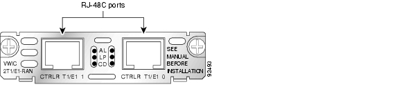
Contained in a circuit card enclosure, the Cisco 2-port T1/E1-RAN interface card weighs from 0.12 to 0.18 pounds (56 to 82 g) and it measures 0.8 in. high x 3.1 in. wide x 4.8 in. deep (2.03 cm x 7.87 cm x 12.2 cm). Each Cisco 2-port T1/E1-RAN interface card provides two RJ-48C ports. Each RJ-48C port supports either T1 or E1. This T1/E1 VWIC slides into a Cisco MWR 1941-DC-A router VWIC slot or network module slot and connects directly to the backplane, where each card connects to power and communications.
Faceplate Features
On the Cisco 2-port T1/E1-RAN interface card faceplate (see Figure 1), six LEDs (labeled AL for alarm, LP for loopback or line state, and CD for data carrier detect) are provided (see Table 1 for a description). The RJ-48C connectors (also located on the front panel) are labeled CTRLR T1/E1 1 for controller T1/E1 serial interface 1 and CTRLR T1/E1 0 for controller T1/E1 serial interface 0 (see the "Cables, Connectors, and Pinouts" section for more information).
Figure 1 Cisco 2-port T1/E1-RAN Interface Card Front Panel
LEDs
The Cisco 2-port T1/E1-RAN interface card has six LEDs (three for each T1/E1 port) as described in Table 1.
Cables, Connectors, and Pinouts
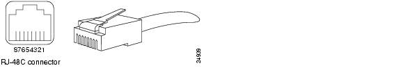
The T1/E1 interface ports on the Cisco 2-port T1/E1-RAN interface card are RJ-48C connectors for both T1 and E1.
The pinout orientation and description are described in the following sections.
Pinout Orientation
Figure 2 shows the orientation of the Cisco 2-port T1/E1-RAN interface card RJ-48C connectors.
Figure 2 RJ-48C Connection
Pinout Description
Table 2 identifies the pinouts of the Cisco 2-port T1/E1-RAN interface card RJ-48C connectors for both the shielded and unshielded cables for either T1 or E1 (see "Connecting the Cisco 2-port T1/E1-RAN Interface Card" section for information about connecting your cables to the Cisco 2-port T1/E1 RAN Interface card.
Note
Specifications
Table 3 lists the physical and environmental specifications for the Cisco 2-port T1/E1-RAN interface card.
Standards Compliance Specifications
When properly installed in the Cisco MWR 1941-DC-A router, the Cisco 2-port T1/E1-RAN interface card complies with the standards listed in Tables 4 and 5.
Table 4 T1 Standards Compliance
Compliance
ANSI1 T1.403
ATT2 54016
Bellcore3 —AT&T Accunet (62411)
CS4 -03
FCC5 Part 68; FCC Part 15 Class B, T1
Canada (CSA6 950, T1; CSA C108.8 Class A, T1)
Japan (VCCI7 Class 2, VCCI:V-3/97.04, T1, JATE8 Green Book, IEC950)
U.K. (BS6301, EN60950, EN41003)Safety conformance
UL9 1950, T1
1 ANSI = American National Standards Institute
2 ATT = American Telephone & Telegraph
3 Bellcore = Bell Communications Research
4 CS = Compliance Specification
5 FCC = U.S. Federal Communications Commission
6 CSA = Canadian Standards Association
7 VCCI = Voluntary Control Council for Interference from Information Technology Equipment
8 JATE = Japanese Approvals Institute for Telecommunications Equipment
9 UL = Underwriters Laboratories
Table 5 E1 Standards Compliance
Compliance
Australia (ACA TS1 016, AS/NZS2 3548:1995)
Europe (EN55022 Class B, EN55102-1, EN55102-2, CTR12, EN60950, EN50082-1:1992, EN55022:1994)
France (NFC98020, EN60950, EN41003)
Germany (TUV GS, EN60950; VDE 0878 part 3 and 30)
Sweden (SS447-2-22, SS636334, EN60950)
UK (NTR4)CCITT/ITU3 G.704, I.431
ETSI4 NET5, ETS300156
TBR5 4
CTR6 -13
ETS 300011
ITU I.431
1 ACA TS = Australian Communications Authority Technical Standards
2 AS/NZS = Australian/New Zealand Standard
3 CCITT/ITU = Consultive Committee for International Telegraphy/International Telecommunications Union
4 ETSI = European Telecommunications Standard Institute
5 TBR = Technical Business for Regulation
6 CTR = Common Technical Requirements
Safety Guidelines
This section includes:
•
•
•
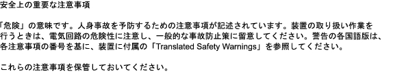
Safety Warnings
Safety warnings appear throughout this publication in procedures that, if performed incorrectly, might harm you. A warning symbol precedes each warning statement. The safety warnings provide safety guidelines that you should follow when working with any equipment that connects to electrical power or telephone wiring. Included in the warnings are translations in several languages. (See the Cisco Regulatory Compliance and Safety Information for the Cisco MWR 1941-DC-A Mobile Wireless Edge Router document for detailed information about compliance guidelines and translated safety warnings.)
DC Power Disconnection Warning
Safety Information Referral Warning
Qualified Personnel Warning
Blank Faceplate Installation Requirement Warning
Electrical Equipment Guidelines
Follow these basic guidelines when working with any electrical equipment:
•
•
•
•
•
Telephone Wiring Guidelines
Use the following guidelines when working with any equipment that is connected to telephone wiring or to other network cabling:
•
•
•
•
Preventing Electrostatic Discharge Damage
Electrostatic discharge (ESD) damage, which can occur when electronic modules or components are improperly handled, results in complete or intermittent failures. Port adapters and processor modules comprise printed circuit boards that are fixed in metal carriers. Electromagnetic interference (EMI) shielding and connectors are integral components of the carrier. Although the metal carrier helps to protect the board from ESD, use a preventive antistatic strap during handling.
Following are guidelines for preventing ESD damage:
•
•
•
•
•
•
•
•
Caution
FCC Class A Compliance
This equipment has been tested and found to comply with the limits for a Class A digital device, pursuant to part 15 of the FCC rules. These limits are designed to provide reasonable protection against harmful interference when the equipment is operated in a commercial environment. This equipment generates, uses, and can radiate radio-frequency energy and, if not installed and used in accordance with the instruction manual, may cause harmful interference to radio communications. Operation of this equipment in a residential area is likely to cause harmful interference, in which case users will be required to correct the interference at their own expense.
You can determine whether your equipment is causing interference by turning it off. If the interference stops, it was probably caused by the Cisco equipment or one of its peripheral devices. If the equipment causes interference to radio or television reception, try to correct the interference by using one or more of the following measures:
•
•
•
•
Installing the Cisco 2-port T1/E1-RAN Interface Card
The following sections describe how to install the Cisco 2-port T1/E1-RAN interface card in a Cisco MWR 1941-DC-A router:
•
Note
Required Tools
In addition to the Cisco 2-port T1/E1-RAN interface card and the Cisco MWR 1941-DC-A router, you need the following items to install and connect your module:
•
•
•
Inserting a Cisco 2-port T1/E1-RAN Interface Card
To insert a Cisco 2-port T1/E1-RAN interface card into a Cisco MWR 1941-DC-A router, follow this procedure.
Caution
Caution
Warning
Warning
Step 1
Caution
Step 2
Step 3
Step 4
Step 5
Step 6
Step 7
Proceed to the next section, "Connecting the Cisco 2-port T1/E1-RAN Interface Card", to continue the installation.
Connecting the Cisco 2-port T1/E1-RAN Interface Card
How you connect the ports of the Cisco 2-port T1/E1-RAN interface card depends on whether you are using the Cisco MWR 1941-DC-A router in a redundant or a non-redundant configuration (see the "Cables, Connectors, and Pinouts" section for a description of the RJ-48C connector pinout for both shielded and unshielded cables.
Note
For information on Cisco MWR 1941-DC-A router implementations, see the Cisco MWR 1941-DC-A Mobile Wireless Edge Router Software Configuration Guide.
For redundant configurations, go to the "Redundant Configuration" section.
For non-redundant configurations, go to the "Non-redundant Configuration" section.
Redundant Configuration
For redundant configurations, use a Y-cable (see the "Y-Cable Specifications" section for details on how to use the Y-cable).
Note
Step 1
Step 2
Step 3
Step 4
Step 5
Step 6
Non-redundant Configuration
For non-redundant configurations, use a straight-through, shielded RJ-48C-to-RJ-48C cable.
Note
Step 1
Step 2
Step 3
Step 4
Step 5
Proceed to the "Configuring the Cisco 2-port T1/E1-RAN Interface Card" section to continue the installation.
Configuring the Cisco 2-port T1/E1-RAN Interface Card
For information about configuring the Cisco 2-port T1/E1-RAN interface cards, see the Cisco MWR 1941-DC-A Mobile Wireless Edge Router Software Configuration Guide.
Y-Cable Specifications
As described in the "Connecting the Cisco 2-port T1/E1-RAN Interface Card" section, depending on the Cisco MWR 1941-DC-A router implementation, the Cisco 2-port T1/E1-RAN interface card can be used in a standalone or in a redundant router configuration. For redundant configurations, a special Y-cable is required to connect the active and standby routers. The Y-cable provides a dual E1 or T1 PRI connection.
This section describes the specifications of the Y-cable.
•
•
•
•
•
Related Documentation
This document provides information on the VWIC-2T1/E1-RAN interface card and supplements the Cisco Interface Modules Hardware Installation Guide.
Use this document with the following guides:
•
–
–
–
•
–
–
•
–
Obtaining Documentation
Cisco documentation and additional literature are available on Cisco.com. Cisco also provides several ways to obtain technical assistance and other technical resources. These sections explain how to obtain technical information from Cisco Systems.
Cisco.com
You can access the most current Cisco documentation at this URL:
http://www.cisco.com/univercd/home/home.htm
You can access the Cisco website at this URL:
You can access international Cisco websites at this URL:
http://www.cisco.com/public/countries_languages.shtml
Documentation DVD
Cisco documentation and additional literature are available in a Documentation DVD package, which may have shipped with your product. The Documentation DVD is updated regularly and may be more current than printed documentation. The Documentation DVD package is available as a single unit.
Registered Cisco.com users (Cisco direct customers) can order a Cisco Documentation DVD (product number DOC-DOCDVD=) from the Ordering tool or Cisco Marketplace.
Cisco Ordering tool:
http://www.cisco.com/en/US/partner/ordering/
Cisco Marketplace:
http://www.cisco.com/go/marketplace/
Ordering Documentation
You can find instructions for ordering documentation at this URL:
http://www.cisco.com/univercd/cc/td/doc/es_inpck/pdi.htm
You can order Cisco documentation in these ways:
•
http://www.cisco.com/en/US/partner/ordering/
•
Documentation Feedback
You can send comments about technical documentation to bug-doc@cisco.com.
You can submit comments by using the response module (if present) behind the front cover of your document or by writing to the following address:
Cisco Systems
Attn: Customer Document Ordering
170 West Tasman Drive
San Jose, CA 95134-9883We appreciate your comments.
Cisco Product Security Overview
Cisco provides a free online Security Vulnerability Policy portal at this URL:
http://www.cisco.com/en/US/products/products_security_vulnerability_policy.html
From this site, you can perform these tasks:
•
•
•
A current list of security advisories and notices for Cisco products is available at this URL:
If you prefer to see advisories and notices as they are updated in real time, you can access a Product Security Incident Response Team Really Simple Syndication (PSIRT RSS) feed from this URL:
http://www.cisco.com/en/US/products/products_psirt_rss_feed.html
Reporting Security Problems in Cisco Products
Cisco is committed to delivering secure products. We test our products internally before we release them, and we strive to correct all vulnerabilities quickly. If you think that you might have identified a vulnerability in a Cisco product, contact PSIRT:
•
•
Tip
Never use a revoked or an expired encryption key. The correct public key to use in your correspondence with PSIRT is the one that has the most recent creation date in this public key server list:
http://pgp.mit.edu:11371/pks/lookup?search=psirt%40cisco.com&op=index&exact=on
In an emergency, you can also reach PSIRT by telephone:
•
•
Obtaining Technical Assistance
For all customers, partners, resellers, and distributors who hold valid Cisco service contracts, Cisco Technical Support provides 24-hour-a-day, award-winning technical assistance. The Cisco Technical Support Website on Cisco.com features extensive online support resources. In addition, Cisco Technical Assistance Center (TAC) engineers provide telephone support. If you do not hold a valid Cisco service contract, contact your reseller.
Cisco Technical Support Website
The Cisco Technical Support Website provides online documents and tools for troubleshooting and resolving technical issues with Cisco products and technologies. The website is available 24 hours a day, 365 days a year, at this URL:
http://www.cisco.com/techsupport
Access to all tools on the Cisco Technical Support Website requires a Cisco.com user ID and password. If you have a valid service contract but do not have a user ID or password, you can register at this URL:
http://tools.cisco.com/RPF/register/register.do
Note
Submitting a Service Request
Using the online TAC Service Request Tool is the fastest way to open S3 and S4 service requests. (S3 and S4 service requests are those in which your network is minimally impaired or for which you require product information.) After you describe your situation, the TAC Service Request Tool provides recommended solutions. If your issue is not resolved using the recommended resources, your service request is assigned to a Cisco TAC engineer. The TAC Service Request Tool is located at this URL:
http://www.cisco.com/techsupport/servicerequest
For S1 or S2 service requests or if you do not have Internet access, contact the Cisco TAC by telephone. (S1 or S2 service requests are those in which your production network is down or severely degraded.) Cisco TAC engineers are assigned immediately to S1 and S2 service requests to help keep your business operations running smoothly.
To open a service request by telephone, use one of the following numbers:
Asia-Pacific: +61 2 8446 7411 (Australia: 1 800 805 227)
EMEA: +32 2 704 55 55
USA: 1 800 553-2447For a complete list of Cisco TAC contacts, go to this URL:
http://www.cisco.com/techsupport/contacts
Definitions of Service Request Severity
To ensure that all service requests are reported in a standard format, Cisco has established severity definitions.
Severity 1 (S1)—Your network is "down," or there is a critical impact to your business operations. You and Cisco will commit all necessary resources around the clock to resolve the situation.
Severity 2 (S2)—Operation of an existing network is severely degraded, or significant aspects of your business operation are negatively affected by inadequate performance of Cisco products. You and Cisco will commit full-time resources during normal business hours to resolve the situation.
Severity 3 (S3)—Operational performance of your network is impaired, but most business operations remain functional. You and Cisco will commit resources during normal business hours to restore service to satisfactory levels.
Severity 4 (S4)—You require information or assistance with Cisco product capabilities, installation, or configuration. There is little or no effect on your business operations.
Obtaining Additional Publications and Information
Information about Cisco products, technologies, and network solutions is available from various online and printed sources.
•
http://www.cisco.com/go/marketplace/
•
•
•
http://www.cisco.com/go/iqmagazine
•
•
http://www.cisco.com/en/US/learning/index.html
![]()
![]()
![]()
![]()
![]()
![]()
![]()
![]()
Posted: Wed Jul 19 10:56:46 PDT 2006
All contents are Copyright © 1992--2006 Cisco Systems, Inc. All rights reserved.
Important Notices and Privacy Statement.