|
|

Table Of Contents
"Deployment Guide: Cisco Guest Access Using the Cisco Wireless LAN Controller"
Configuring Guest Access on the Cisco Wireless LAN Controller
Creating Guest Access Accounts
Creating a Guest Access Account Using the Local Network User Option
Creating a Guest Access Account Using the Lobby Ambassador Option
Web Authentication Using Mobility Anchor Feature on Controller
Web Authentication Using an External RADIUS Server
Web Authentication Using an External Web Server
Web Authentication Using Cisco Building Broadband Service Manager
"Deployment Guide: Cisco Guest Access Using the Cisco Wireless LAN Controller"
August 2006
Contents
"Configuring Guest Access on the Cisco Wireless LAN Controller" section
"Creating Guest Access Accounts" section
"Web Authentication Process" section
"Related Documentation" section
Overview
Today, leading companies are faced with providing network access for their customers, partners, vendors, contractors and other visitors. This expanded network access enables higher productivity, improved collaboration, and better service; however, it necessitates that a guest access policy be established to address increased network usage and security issues.
By implementing a broad-based solution to guest access, companies can control network access, eliminate ad hoc IT support requirements, track guest network usage and securely separate guest traffic from internal resources.
The need for guest access has evolved as the needs of guests have evolved. Today, with laptops, networked applications, and digital phone lines, a visiting guest is disempowered without continued access to these technologies.
Guest networks are network connections provided by an enterprise to enable their guests to gain access to the Internet, and the guests' own enterprise without compromising the security of the host enterprise. The main technical requirements for a complete guest access solution are outlined below:
•
Complete integration into the enterprise network and its resources
•
•
•
In this document, we have included various scenarios where the Cisco Wireless LAN Controller can be used to deploy a guest access solution over the corporate network.
Terms and Acronyms
Table 1 Key Terms Used in this Deployment Guide
Configuring Guest Access on the Cisco Wireless LAN Controller
An existing enterprise wired and wireless network infrastructure can be used to implement a wireless guest network. No separate, overlay network is required to support guest access.
Therefore, the overall implementation and maintenance costs of a guest network are greatly reduced.
To successfully implement a guest network on an existing wired or wireless network, the following critical elements are required:
•
•
•
•
Initial Configuration
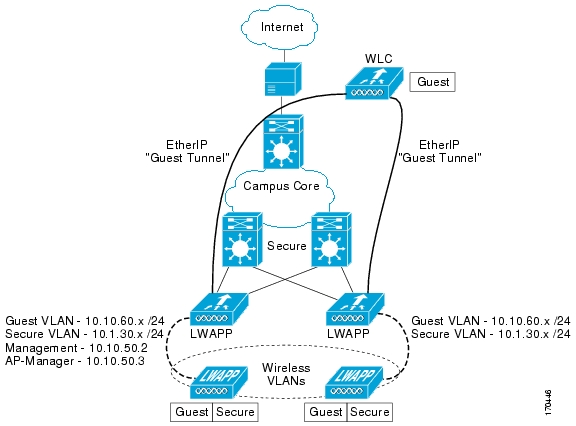
Figure 1 shows an example of basic guest access using the Cisco wireless LAN controller. The configuration shown is applicable for Cisco controller models 2006, 410x, and 440x.
The wireless LAN controller in the remote office is connected to a WAN infrastructure.
•
–
–
•
•
•
•
Figure 1 Configuration Example - Remote Office
Connecting to the Neighbor Switch
The WLC is connected to the neighboring Catalyst 3750 switch using only 1 port. The neighbor switch port is configured as an 802.1Q trunk, and only the appropriate VLANs in this case, specifically VLANs 30, 50 and 60 are allowed. The AP-Manager and Management interfaces are members of VLAN 50 which in this example is configured as the native VLAN in the trunk interface.
The 802.1Q switchport command-line interface (CLI) configuration is as follows:
interface GigabitEthernet1/1description Trunk Port to Cisco WLCswitchport trunk encapsulation dot1qswitchport trunk native vlan 50switchport trunk allowed vlan 30,50,60switchport mode trunkno ip addressConfiguring the Cisco Wireless LAN Controller
The initial configuration of the Cisco wireless LAN controller is done through a console cable connected to the controller. The administrator can configure the system using the Configuration Wizard available on the console port.
Note
The Configuration Wizard is used to configure a number of items as seen in the script example below. Some of the items configured during this process include: the system name, Cisco wireless LAN controller (WLC) administrative user credentials, the Management interface, AP Manager, virtual interfaces, the mobility group name, one SSID, and a RADIUS server.
Welcome to the Cisco Wizard Configuration ToolUse the '-' character to backupSystem Name [Cisco_33:1c:c0]:Enter Administrative User Name (24 characters max): adminEnter Administrative Password (24 characters max): *****Management Interface IP Address: 10.10.50.2Management Interface Netmask: 255.255.255.0Management Interface Default Router: 10.10.50.1Management Interface VLAN Identifier (0 = untagged):Management Interface Port Num [1 to 4]: 1Management Interface DHCP Server IP Address: 10.1.1.11AP Manager Interface IP Address: 10.10.50.3AP-Manager is on Management subnet, using same valuesAP Manager Interface DHCP Server (10.1.1.11):Virtual Gateway IP Address: 1.1.1.1Mobility/RF Group Name: mobile-1Network Name (SSID): guestAllow Static IP Addresses [YES][no]: noConfigure a RADIUS Server now? [YES][no]: YESEnter the RADIUS Server's Address: 10.1.1.11Enter the RADIUS Server's Port [1812]:Enter the RADIUS Server's Secret: ciscoEnter Country Code (enter 'help' for a list of countries) [US]: USEnable 802.11b Network [YES][no]: YESEnable 802.11a Network [YES][no]: YESEnable 802.11g Network [YES][no]: YESEnable Auto-RF [YES][no]: YESConfiguration saved!Resetting system with new configuration....
Note
Modifying the VLAN Interfaces for the Guest and Secure (Employee) VLAN
The guest VLAN and the employee (secure) VLAN must be modified from the configuration initially assigned during the configuration wizard process.
Note
To modify the guest and employee (secure) VLAN interfaces, follow these steps:
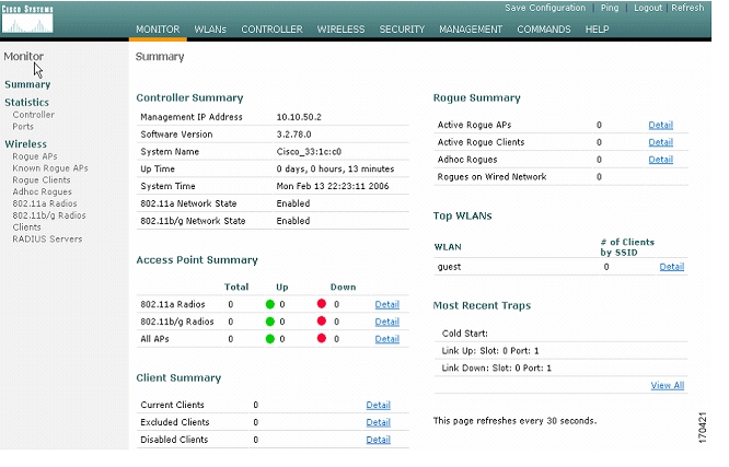
Step 1
The window seen in Figure 2 appears.
Step 2
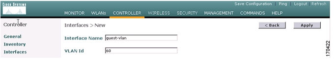
Step 3
In the window that appears ( Figure 3), enter a name in the Interface Name field and assign a value to the VLAN ID field. For this example, we entered guest-vlan and 60, respectively.
Step 4
Step 5
Step 6
Step 7
Step 8
Step 9
Step 10
For this example, we named the VLAN secure-vlan with a VLAN ID of 30.
Note
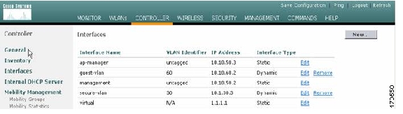
Figure 2 Initial Configuration of the WLC as Created by the Configuration Wizard
Figure 3 Configuring VLAN Interface for Guest and Secure (Employee) Wireless LAN Access
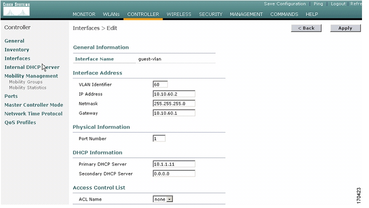
Figure 4 Entering Configuration Details for the Guest VLAN Interface
Figure 5 Summary Page Showing Guest and Secure VLAN
Modifying the WLAN Instance to Define Security Policies
After configuring the IP address for the guest and secure VLAN interfaces for the wireless LAN, you can define security polices such as web authentication (a Layer 3 security policy) for the guest and secure (employee) wireless LAN access interfaces.
To define security policies for the VLANs, follow these steps:
Step 1
Step 2
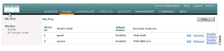
Figure 6 WLANs Summary Page Showing Existing Defined Wireless LANs
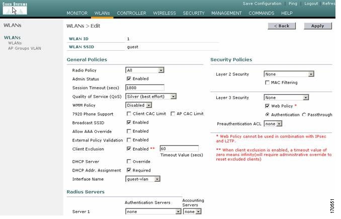
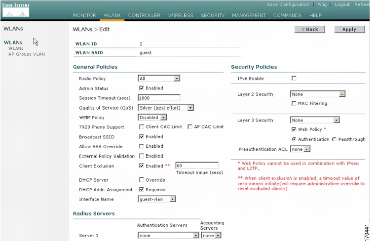
Figure 7 WLANs > Edit Page for the Guest WLAN
Step 3
This enables dynamic IP address assignment.
Step 4
For this example, the interface for the guest WLAN is guest-vlan (assigned in the "Modifying the VLAN Interfaces for the Guest and Secure (Employee) VLAN" section).
Step 5
Note
Step 6
Step 7
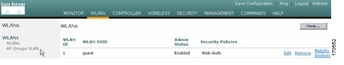
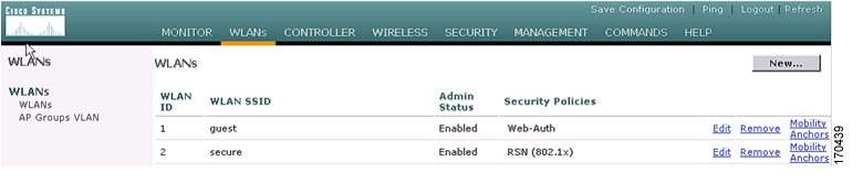
For this example, we want to verify that web authentication (Web-Auth), the assigned security policy, is enabled for the guest WLAN.
Figure 8 WLANs Page Verifying Security Policy Assigned to Guest WLAN
Step 8
Step 9
Step 10
Step 11
Step 12
For this example, we chose WPA2 with 802.1x authentication from a RADIUS server.
Note
Note
Step 13
Step 14
Figure 9 WLANs Page Verifying Security Policy Assigned to Secure (Employee) WLAN
Creating Guest Access Accounts
If you are using controllers running controller software release 3.2, see the "Creating a Guest Access Account Using the Local Network User Option" section.
The Local Network User option allows you to directly add users to the local database of the controller. The local user database is limited to a maximum of 2048 entries and is set to a default value of 512 entries at the Security > General page. This database is shared by local management users (including lobby ambassadors), net users (including guest users), MAC filter entries, and disabled clients. Together, all of these types of users cannot exceed the configured database size.
If you are using controllers running software release 4.0 or greater, see the "Creating a Guest Access Account Using the Lobby Ambassador Option" section.
The Lobby Ambassador option is a two-step process. The first step is to create a lobby administrator account, also known as a lobby ambassador account. The second step is to create guest accounts when the lobby ambassador is active. The lobby ambassador has limited configuration privileges and only has access to the web pages used to manage the guest accounts. The lobby ambassador can specify the amount of time that the guest user accounts remain active. After the specified time elapses, the guest user accounts expire automatically.
Creating a Guest Access Account Using the Local Network User Option
You must create a local net user username and password to use when logging in as a Web Authentication client to the wireless LAN.
To create a username and a password, follow these steps:
Step 1
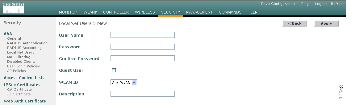
Step 2
The Local Net Users > New page appears ( Figure 10).
Figure 10 Local Net Users > New Page
Step 3
Step 4
Step 5
Step 6
Step 7
Step 8
Note
Step 9
Step 10
Step 11
Creating a Guest Access Account Using the Lobby Ambassador Option
You can create a lobby ambassador account on the controller through either its web interface or the CLI. Examples of both are provided below.
Creating a Lobby Ambassador Account Using the Controller Web Interface
To create a lobby ambassador account on the controller using the web interface, follow these steps:
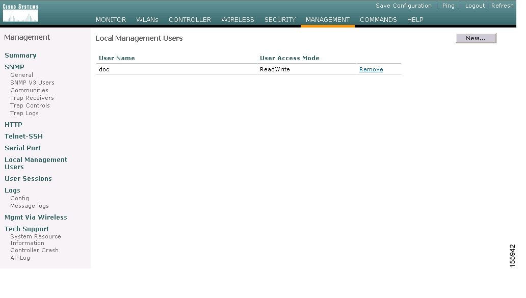
Step 1
Note
Figure 11 Local Management Users Page
Step 2
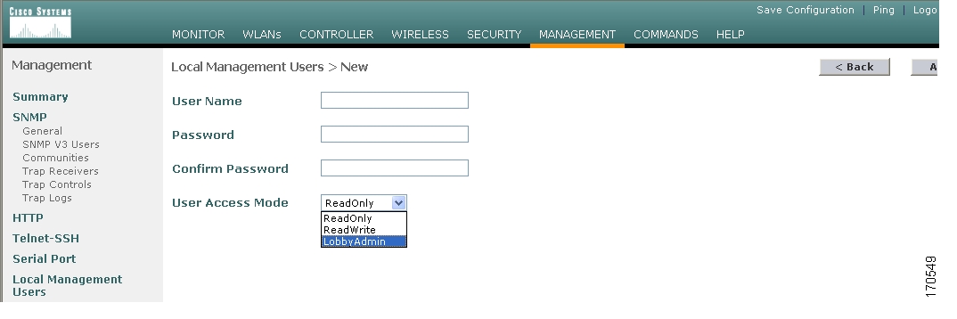
The Local Management Users > New page appears ( Figure 12).
Figure 12 Local Management Users > New Page
Step 3
Step 4
Note
Step 5
Note
Step 6
Step 7
Creating a Lobby Ambassador Account Using the Command-Line Interface
Enter this command to create a lobby ambassador account using the controller CLI:
config mgmtuser add lobbyadmin_username lobbyadmin_pwd lobby-admin
Note
Creating Guest User Accounts as a Lobby Ambassador
Follow these steps to create guest user accounts:
Note
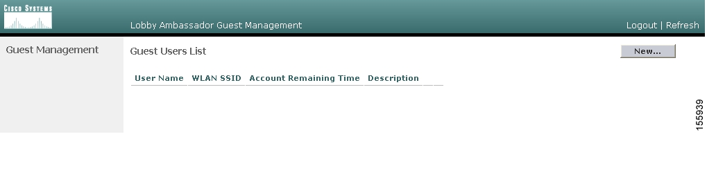
Step 1
The Lobby Ambassador Guest Management > Guest Users List page appears ( Figure 13).
Figure 13 Lobby Ambassador Guest Management > Guest Users List Page
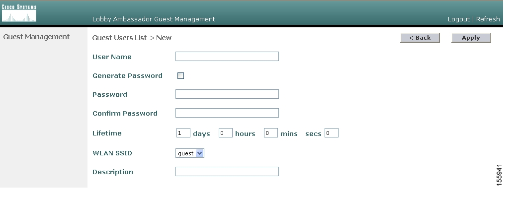
Step 2
Figure 14 Guest Users List > New Page
Step 3
Step 4
•
•
Note
Step 5
Default: 1 day
Range: 5 minutes to 30 days
Note
Note
Step 6
Note
Step 7
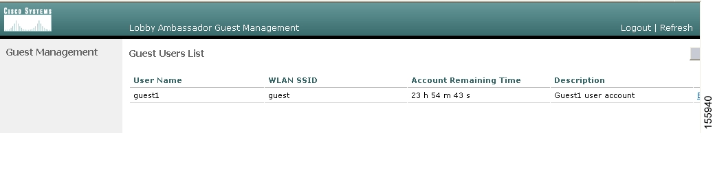
Step 8
Figure 15 Lobby Ambassador Guest Management > Guest Users List Page
From this page, you can see all of the guest user accounts, their WLAN SSIDs, and their lifetimes. You can also edit or remove a guest user account. When you remove a guest user account, all of the clients that are using the guest WLAN and are logged in using that account's username are deleted.
Step 9
Viewing Guest User Accounts
After a lobby ambassador creates the guest user accounts, the system administrator can view them from the controller GUI or CLI.
Using the GUI to View Guest Accounts
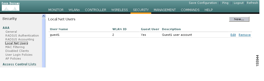
To view guest user accounts using the controller GUI, click Security and then Local Net Users under AAA. The Local Net Users page appears ( Figure 16).
Figure 16 Local Net Users Page
From the Local Net Users page, the system administrator can see all of the local net user accounts (including guest user accounts) and can edit or remove them as desired. When you remove a guest user account, all of the clients that are using that guest WLAN and are logged in using that account's username are deleted.
Using the CLI to View Guest Accounts
To view all of the local net user accounts (including guest user accounts) using the controller CLI, enter this command: show netuser summary
Web Authentication Process
Web authentication is a Layer 3 security feature that causes the controller to block IP traffic (except DHCP-related packets) until the client has correctly supplied a valid username and password. When you use web authentication to authenticate clients, you must define a username and password for each client. Then when the clients attempt to join the wireless LAN, their users must enter the username and password when prompted by a login window.
Using the Web Authentication feature on a Cisco wireless LAN controller, we can authenticate a guest user on the wireless LAN controller, an external web server, an external database on a RADIUS server or via the Cisco Building Broadband Service Manager (BBSM).
These four methods are described in the following sections:
"Web Authentication Using Mobility Anchor Feature on Controller" section
"Web Authentication Using an External RADIUS Server" section
"Web Authentication Using an External Web Server" section
"Web Authentication Using Cisco Building Broadband Service Manager" section
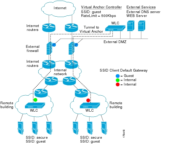
Web Authentication Using Mobility Anchor Feature on Controller
Guest tunneling provides additional security for guest-user access to the corporate wireless network, ensuring that guest users are unable to access the corporate network without first passing through the corporate firewall. Instead of extending the DMZ virtual LAN (VLAN) to each wireless LAN controller on the network, a Cisco 4100 or 4400 series wireless LAN controller or Cisco WiSM can be used in the DMZ as an anchor controller to terminate traffic from remote controllers.
Internal employee user traffic is segregated from guest user traffic using Ethernet over IP (EoIP) tunnels and VLANs between the remote controllers and the DMZ controller.
Guest Tunneling Support on Cisco Products
Guest Tunneling provides additional security for guest-user access to the corporate wireless network across most wireless LAN controller platforms ( Table 2).
Table 2 Guest Tunneling Support on Wireless LAN Controller Platform
Cisco 4100 series wireless LAN controllers
Y
Y
N
Cisco 4400 series wireless LAN controllers
Y
Y
Y
Cisco 2000 series wireless LAN controllers1
N
Y
Y
Cisco 6500 series (WiSM)
---
Y
Y
Cisco 3750 series with integrated wireless LAN controller
---
N
Y
Cisco wireless LAN controller module for Integrated Service Routers1
---
Y
Y
1 Cannot be used for anchor functions (tunnel termination, web authentication and access control); however, origination of guest controller tunnels is supported. When a user associates with a service set identifier (SSID) that is designated as the guest SSID, the user's traffic is tunneled to the DMZ Anchor controller which can route the traffic to the DMZ network outside of the corporate firewall.
s
In guest tunneling scenarios:
•
•
Mobility is supported as a client device roams between wireless LAN controllers.
Each DMZ anchor controller can support 40 tunnels from various inside controllers. These tunnels are established from each controller for each SSID using the mobility anchor feature, meaning that many wireless clients can ride the tunnel.
For a customer with many remote sites, it is now possible to forward different types of guest traffic from different sites to different DMZ Anchor controllers, or to the same DMZ Anchor controller with different wireless LANs. Any user getting placed on the DMZ can use the AAA-override feature to apply RADIUS Vendor Specific Attributes (VSAs) on a per-session basis.
Guest tunneling provides additional security for guest-user access to the corporate wireless network.
Note
Figure 17 Web Authentication Using the Mobility Anchor Controller Feature
Anchor Controller Selection
The anchor function on a controller includes tunnel termination, web authentication, and access control.
A Cisco 4400 series controller is the most cost effective controller that can be used as an Anchor controller in the DMZ.
•
•
–
–
Creating and Adding Controllers to the Same Mobility Group
To configure a mobility group, follow these steps:
Step 1
Note
Step 2
Figure 18 Controller > Static Mobility Group Members Page
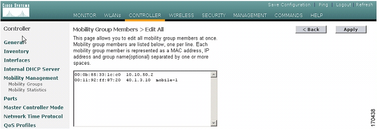
Step 3
Figure 19 Mobility Group Members > Edit All
Step 4
Note
Step 5
Step 6
Step 7
Note
Step 8
You are now ready to create the mobility anchor between the remote and DMZ controllers.
Configuring Auto-Anchor Mobility
You can use auto-anchor mobility (or guest WLAN mobility) to improve load balancing and security for roaming clients on your wireless LANs. Under normal roaming conditions, client devices join a wireless LAN and are anchored to the first controller that they contact. If a client roams to a different subnet, the controller to which the client roamed sets up a foreign session for the client with the anchor controller.
However, using the auto-anchor mobility feature, you can specify a controller or set of controllers as the anchor points for clients on a wireless LAN. In auto-anchor mobility mode, a subset of a mobility group is specified as the anchor controllers for a wireless LAN. You can use this feature to restrict a wireless LAN to a single subnet, regardless of a client's entry point into the network. Clients can then access a guest wireless LAN throughout an enterprise but still be restricted to a specific subnet.
Auto-anchor mobility can also provide geographic load balancing because the wireless LANs can represent a particular section of a building (such as a lobby, a restaurant, and so on), effectively creating a set of home controllers for a wireless LAN. Instead of being anchored to the first controller that they happen to contact, mobile clients can be anchored to controllers that control access points in a particular vicinity.
Configuration Guidelines
Keep these guidelines in mind when configuring auto-anchor mobility:
•
•
•
To configure auto-anchor mobility, follow these steps:
Step 1
Figure 20 Controller > WLANs Page
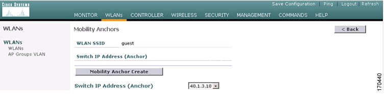
Step 2
Figure 21 Mobility Anchors Page
Step 3
Step 4
Note
Step 5
Step 6
Step 7
Verifying Mobility Anchor Configuration
You can use the CLI to verify the configuration of the mobility anchor configuration for the remote and DMZ anchor controller.
To verify the configuration on the remote controller, follow these steps:
(Cisco Controller) >show wlan summaryNumber of WLANs.................................. 2WLAN ID WLAN Name Status Interface Name------- ---------------------- --------- ---------------------------1 guest Enabled guest-vlan2 secure Enabled secure-vlan(Cisco Controller) >show mobility summaryMobility Protocol Port........................... 16666Default Mobility Domain.......................... mobile-1Mobility Group members configured................ 2Switches configured in the Mobility GroupMAC Address IP Address Group Name00:0b:85:33:1c:c0 10.10.50.2 <local>00:11:92:ff:87:20 40.1.3.10 mobile-1(Cisco Controller) >show mobility anchorMobility Anchor Export ListWLAN ID IP Address1 40.1.3.102 40.1.3.10To verify the configuration on the DMZ controller, follow these steps:
(Cisco Controller) >show wlan summaryNumber of WLANs.................................. 2WLAN ID WLAN Name Status Interface Name------- ---------------------- --------- --------------------------------1 secure-1 Enabled management2 guest Enabled guest-vlan(Cisco Controller) >show mobility summaryMobility Protocol Port........................... 16666Mobility Security Mode........................... DisabledDefault Mobility Domain.......................... mobile-1Mobility Group members configured................ 2Switches configured in the Mobility GroupMAC Address IP Address Group Name00:0b:85:33:1c:c0 10.10.50.2 mobile-100:11:92:ff:87:20 40.1.3.10 <local>(Cisco Controller) >show mobility anchorMobility Anchor Export ListWLAN ID IP Address1 40.1.3.10
Note
Note
Running Mobility Ping Tests (Release 4.0 and later)
Controllers belonging to the same mobility group communicate with each other by controlling information over a well-known UDP port and exchanging data traffic through an Ethernet-over-IP (EoIP) tunnel. Because UDP and EoIP are not reliable transport mechanisms, there is no guarantee that a mobility control packet or data packet will be delivered to a mobility peer. Mobility packets may be lost in transit due to a firewall filtering the UDP port or EoIP packets or due to routing issues.
Controller software release 4.0 enables you to test the mobility communication environment by performing mobility ping tests. These tests may be used to validate connectivity between members of a mobility group (including guest controllers).
Note
Two ping tests are available:
•
•
Only one mobility ping test per controller can be run at a time.
Note
Use these commands to run mobility ping tests from the controller CLI.
1.
mping mobility_peer_IP_address
The mobility_peer_IP_address parameter must be the IP address of a controller that belongs to a mobility group.
2.
eping mobility_peer_IP_address
The mobility_peer_IP_address parameter must be the IP address of a controller that belongs to a mobility group.
3.
config msglog level verbose
show msglog
To troubleshoot your controller for mobility ping over UDP, enter this command to display the mobility control packet:
debug mobility handoff enable
Note
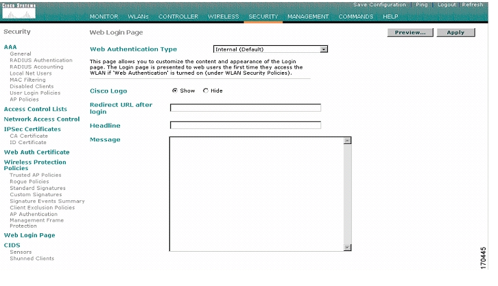
Enabling the Web Login Page on the Controller
After defining the security policies for the guest and secure VLAN interfaces, you need to enable the web login on the controller.
To enable the web login, follow these steps:
Step 1
Step 2
The Web Login Page appears ( Figure 22).
Figure 22 Configuring Web Login Page on Controller
Step 3
Note
Step 4
Step 5
Step 6
Step 7
Step 8
Note
Rebooting the Wireless LAN Controller
To commit the web authentication changes entered in the previous steps, you must reboot the controller.
To reboot the controller, follow these steps:
Step 1
Step 2
Step 3
Web Authentication Using an External RADIUS Server
We can configure the wireless LAN used for guest traffic to authenticate the user from an external RADIUS server; in this example it is 10.1.1.11.
To enable an external RADIUS server to authenticate traffic using the GUI, follow these steps:
Step 1
Figure 23 WLANs > Edit Page
Step 2
Note
Step 3
To enable an external RADIUS server to authenticate traffic using CLI, follow these steps:
Step 1
Step 2
Step 3
Step 4
Note
Step 5
Note
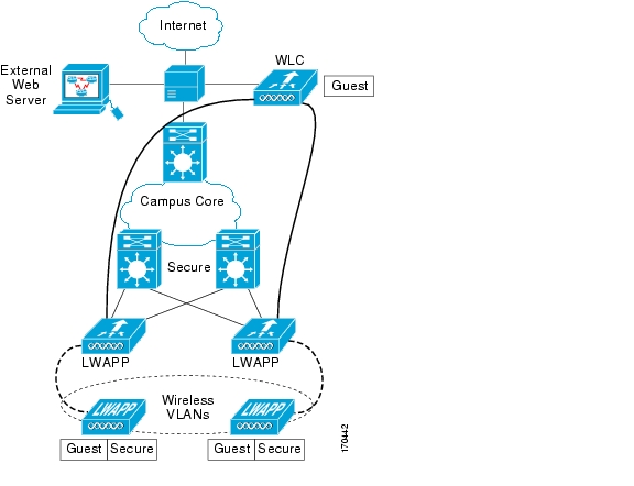
Web Authentication Using an External Web Server
To use a custom web authentication login window configured on an external web server rather than the default web login window of Cisco's wireless LAN controller or the Cisco Building Broadband Service Manager (BBSM), follow the instructions in the GUI or CLI procedure below.
When you enable this feature, the user is automatically directed to your custom login window on the external web server.
Figure 24 Using an External Web Server to Authenticate a Guest User
Note
Note
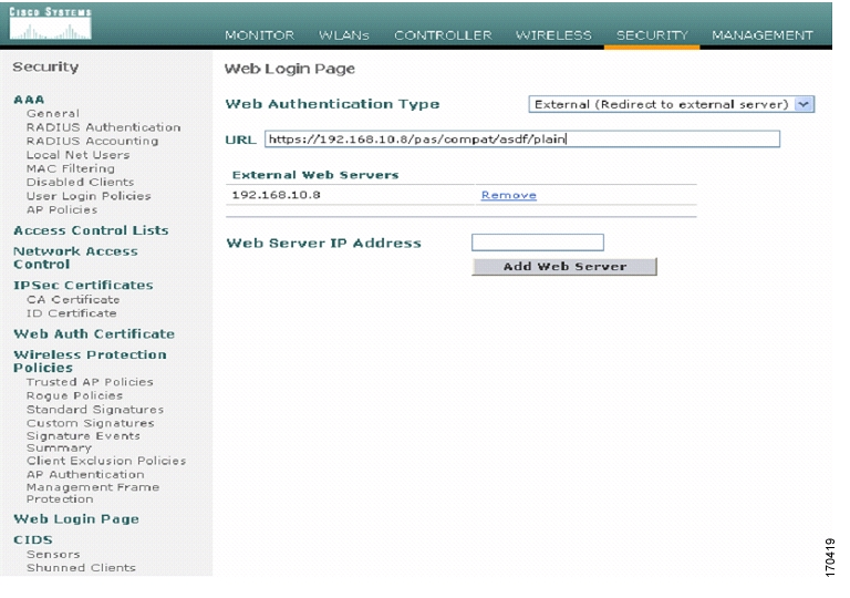
Using the GUI to Choose a Customized Web Authentication Login Window from an External Web Server
To use an external web server for authentication, follow these steps:
Step 1
Figure 25 Security > Web Login Page
Step 2
Step 3
Step 4
This server now appears in the list of external web servers.
Step 5
Step 6
Once authenticated at the external login page of the external web server, a request is sent back to the controller. The controller then submits the username and password for authentication to an external RADIUS server for verification.
If verification at the RADIUS server is successful, the controller web server either forwards the user to the configured redirect URL or to the user's original opening web page.
If verification at the RADIUS server fails, then the controller web server redirects the user back to the customer login URL.
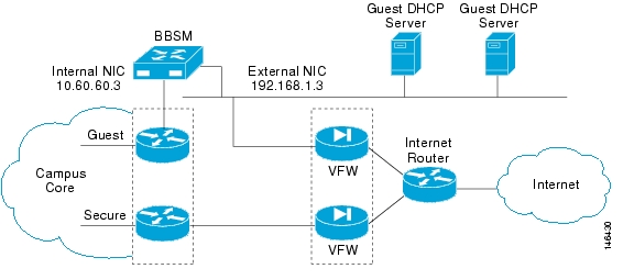
Web Authentication Using Cisco Building Broadband Service Manager
Cisco Building Broadband Service Manager (BBSM) works with Cisco access-layer LAN and wireless LAN products ( Figure 26) to provide a complete solution that enables businesses, venues and service providers to create, market and operate broadband access services in markets such as public hotspots, enterprise, health care and retail. The Enterprise can securely offer their guest's access to the Internet over existing networks.
For more details on configuring BBSM for Web Authentication, please refer to the Cisco BBSM 5.3 Configuration Guide.
Figure 26 Guest Access Deployment Using BBSM.
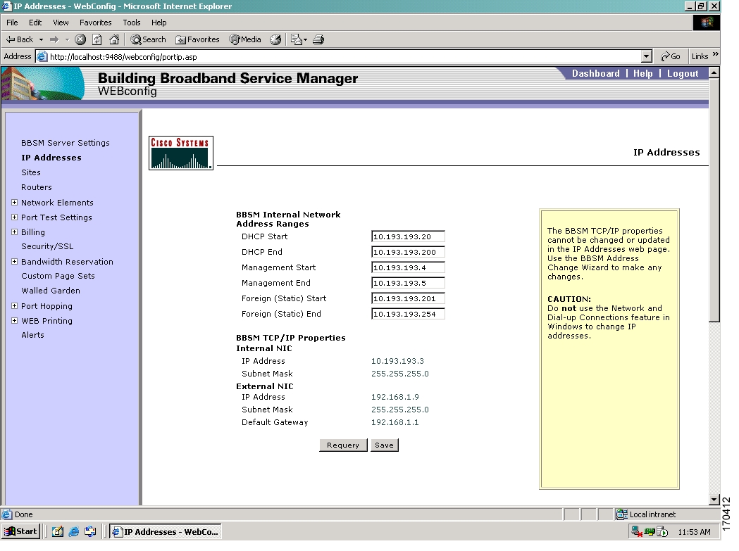
Configuring the BBSM Server to Authenticate Guest Traffic
Using the address change wizard, follow these steps to configure the BBSM server to authenticate guest traffic:
Step 1
Step 2
These IP addresses should be served by the BBSM or external DHCP server.
Step 3
The management addresses define the range of IP addresses that will pass through BBSM and will not require redirection for external web authentication. Examples of these devices are routers, switches, and access points.
Step 4
Users assigned these addresses will not be able to request dynamic (DHCP) IP address assignment.
Step 5
Figure 27 Entering Internal Network Addresses for BBSM Server to Support Authentication
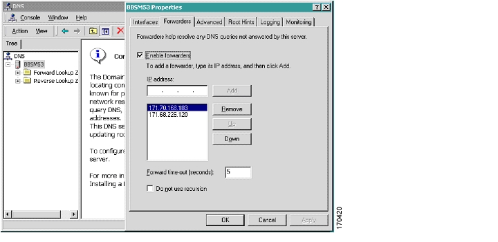
Enabling DNS Forwarding
After entering the appropriate internal IP addresses for the BBSM server, enable DNS forwarding on the server.
Domain Name System (DNS) forwarding allows DNS requests to be relayed to a remote DNS server.
BBSM is not configured as a DNS server; instead it acts as a DNS forwarder for its clients and its own DNS requests. These DNS requests, such as a request for www.cisco.com, are mapped with their IP addresses so that the Internet routers can locate the web server with the content.
Note
Note
To enable DNS forwarding on your server, follow these steps:
Step 1
Step 2
Figure 28 Configuring DNS Forwarding in the Server Properties Window
Step 3
Step 4
Step 5
If you have more than one DNS server IP address, continue to enter them and click Add until they are all in the list. Enter the primary DNS server first. It will appear first in the list. Enter the secondary DNS server second.
Step 6
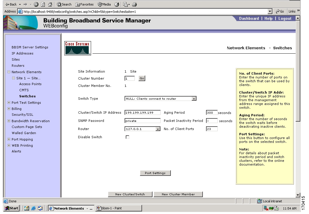
Defining an Access Interface
After enabling DNS forwarding, an access interface is defined on a Layer 3 switch or router interface.
Note
Note
To define an access interface on either a switch or router, follow these steps:
Step 1
Step 2
By selecting this option, BBSM will not try to discover the hosts behind this switch to track their MAC addresses.
Figure 29 Network Elements Page
Step 3
Note
The Network Elements Port Settings page appears. This page is used to define the web page that will be displayed to visiting guests.
Note
Step 4
You are returned to the Switches web page.
Table 3 Switch Fields and Descriptions
Table 4 Port Setting Fields and Descriptions
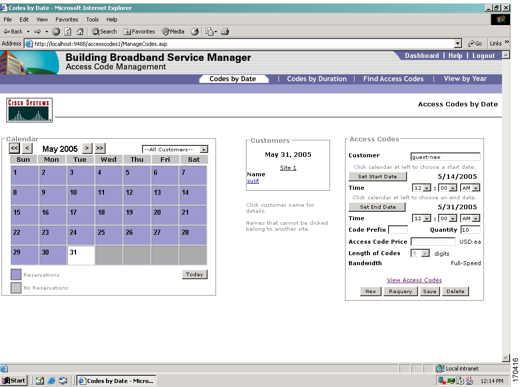
Defining Access Codes (Temporary Credentials)
After defining the access interface, you are ready to define the Internet access code for the guests. With BBSM, Internet access is defined (purchased) in one of two ways:
•
•
Note
To define guest access authentication parameters, follow these steps:
Step 1
Step 2
Step 3
•
•
•
Step 4
Option 2: To create Access Codes by duration, select the Codes by Duration tab.
Enter the appropriate values to define access for the guest given the assignment option chosen.
Figure 30 Access Code Management > Codes by Date Page
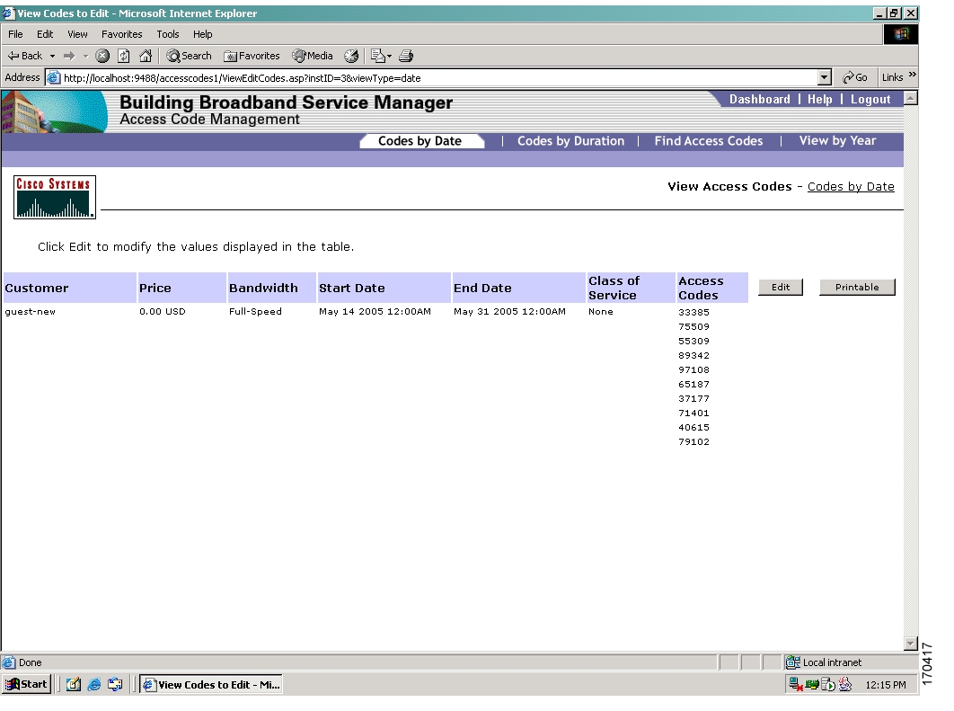
Step 5
Note
Step 6
Figure 31 View Access Codes Page
Note
Note
Modifying PC to Support Wireless Guest Access
After you have defined the access codes using BBSM, you need to make changes to the client on the guest user's PC to support guest access.
The Microsoft Wireless Client on your PC requires minimal changes to support guest access.
To support guest access on your PC, follow these steps:
Step 1
Step 2
Step 3
Step 4
Step 5
Step 6
Step 7
Step 8
and then click on the Add... button.Step 9
Note
Step 10
When you are actively communicating with the wireless LAN you will see a beacon icon in the preferred network box.
Client Login
Once the web authentication method is defined and the client changes are made to the guest user's PC, the user can log on.
To log on as a guest user, follow these steps:
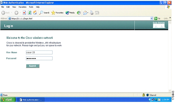
Step 1
Note
Figure 32 Client Login Page
Step 2
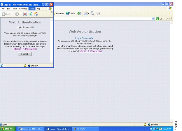
Step 3
Figure 33 Successful Login Page
Troubleshooting
This section provides debugging tips for specific features.
Note
Debugging Mobility Anchor
Mobility hand off and mobility directory debug commands display the guest-tunnel or AnchorExport debugging information in addition to the traditional mobility debugging information.
You will see mobility exchanges [MobileAnchorExport messages (on Foreign) & MobileAnchorExportAck (on Anchor)] when enabling mobility hand off and mobility directory debugs.
Debugging guest tunneling and the Ethernet over IP are both included in the regular mobility debugs:
debug mac addr <client mac address>
debug mobility handoff enable
debug mobility directory enable
debug dhcp packet enable
debug pem state enable
debug pem events enable
debug dot11 mobile enable
debug dot11 state enable
While the data source port is being diagnosed, look for UDP packets with Source/Destination Port=16666. Any EoIP packets can be filtered by using the display filter etherip in the capture taken.
Debug Scripts from the Foreign Controller
(Cisco Controller) > show debugMAC address ................................ 00:40:96:a9:fa:a0Debug Flags Enabled:arp error enabled.bcast error enabled.dhcp packet enabled.dot11 mobile enabled.dot11 state enabledmobility directory enabled.mobility handoff enabled.pem events enabled.pem state enabled.(Cisco Controller) > show timeTime............................................. Tue Feb 14 13:47:31 2006Timezone delta................................... 0:0Daylight savings................................. disabledNTP ServersNTP Polling Interval......................... 86400Index NTP Server------- --------------------------------(Cisco Controller) >Tue Feb 14 13:47:40 2006: Scheduling deletion of Mobile Station: 00:40:96:a9:fa:a0 (callerId: 24) in 5 secondsTue Feb 14 13:47:40 2006: Updated location for station 00:40:96:a9:fa:a0 - old AP 00:00:00:00:00:00-0, new AP 00:0b:85:23:cc:50-0Tue Feb 14 13:47:40 2006: Association received from mobile 00:40:96:a9:fa:a0 on AP 00:0b:85:23:cc:50Tue Feb 14 13:47:40 2006: Initializing policy for mobile 00:40:96:a9:fa:a0Tue Feb 14 13:47:40 2006: pem_api.c:1785 - State Update 00:40:96:a9:fa:a0 from START (0) to AUTHCHECK (2)Tue Feb 14 13:47:40 2006: pem_api.c:1873 - State Update 00:40:96:a9:fa:a0 from AUTHCHECK (2) to L2AUTHCOMPLETE (4)Tue Feb 14 13:47:40 2006: Plumbed mobile LWAPP rule on AP 00:0b:85:23:cc:50 for mobile 00:40:96:a9:fa:a0Tue Feb 14 13:47:40 2006: pem_api.c:2006 - State Update 00:40:96:a9:fa:a0 from L2AUTHCOMPLETE (4) to DHCP_REQD (7)Tue Feb 14 13:47:40 2006: Changing state for mobile 00:40:96:a9:fa:a0 on AP 00:0b:85:23:cc:50 from Probe to AssociatedTue Feb 14 13:47:40 2006: Session Timeout is 1800 - starting session timer for STA 00:40:96:a9:fa:a0Tue Feb 14 13:47:40 2006: Scheduling deletion of Mobile Station: 00:40:96:a9:fa:a0 (callerId: 49) in 1800 secondsTue Feb 14 13:47:40 2006: Sending Assoc Response to station 00:40:96:a9:fa:a0 on BSSID 00:0b:85:23:cc:50 (status 0)Tue Feb 14 13:47:40 2006: Changing state for mobile 00:40:96:a9:fa:a0 on AP 00:0b:85:23:cc:50 from Associated to AssociatedTue Feb 14 13:47:40 2006: Mobility query, Mobile: 00:40:96:a9:fa:a0 PEM State: DHCP_REQDTue Feb 14 13:47:40 2006: Mobility packet sent to:Tue Feb 14 13:47:40 2006: 40.1.3.10, port 16666, Switch IP: 10.10.50.2Tue Feb 14 13:47:40 2006: type: 3(MobileAnnounce) subtype: 0 version: 1 xid: 20 seq: 21 len 120Tue Feb 14 13:47:40 2006: group id: 8980c166 1ac12d02 a250ca56 49c7b762Tue Feb 14 13:47:40 2006: mobile MAC: 00:40:96:a9:fa:a0, IP: 0.0.0.0, instance: 0Tue Feb 14 13:47:40 2006: VLAN IP: 10.10.60.2, netmask: 255.255.255.0Tue Feb 14 13:47:41 2006: Mobility packet sent to:Tue Feb 14 13:47:41 2006: 40.1.3.10, port 16666, Switch IP: 10.10.50.2Tue Feb 14 13:47:41 2006: type: 3(MobileAnnounce) subtype: 0 version: 1 xid: 20 seq: 21 len 120Tue Feb 14 13:47:41 2006: group id: 8980c166 1ac12d02 a250ca56 49c7b762Tue Feb 14 13:47:41 2006: mobile MAC: 00:40:96:a9:fa:a0, IP: 0.0.0.0, instance: 0Tue Feb 14 13:47:41 2006: VLAN IP: 10.10.60.2, netmask: 255.255.255.0Tue Feb 14 13:47:41 2006: Mobility packet retry:, Client: 00:40:96:a9:fa:a0 Peer IP: Groupcast, Anchor IP: 0.0.0.0Tue Feb 14 13:47:43 2006: DHCP proxy received packet, src: 0.0.0.0, len = 300Tue Feb 14 13:47:43 2006: dhcpProxy(): dhcp request, client: 00:40:96:a9:fa:a0: dhcp op: 1, port: 1, encap 0xec03, old mscb port number: 1Tue Feb 14 13:47:43 2006: Dropping DHCP during mobility, chaddr: 00:40:96:a9:fa:a0 siaddr: 0.0.0.0Tue Feb 14 13:47:43 2006: Attempting anchor export for mobile 00:40:96:a9:fa:a0Tue Feb 14 13:47:43 2006: Anchor Export: Client: 00:40:96:a9:fa:a0 Client IP: 0.0.0.0, Anchor IP: 40.1.3.10Tue Feb 14 13:47:43 2006: Mobility packet sent to:Tue Feb 14 13:47:43 2006: 40.1.3.10, port 16666, Switch IP: 10.10.50.2Tue Feb 14 13:47:43 2006: type: 16(MobileAnchorExport) subtype: 0 version: 1 xid: 21 seq: 22 len 244Tue Feb 14 13:47:43 2006: group id: 8980c166 1ac12d02 a250ca56 49c7b762Tue Feb 14 13:47:43 2006: mobile MAC: 00:40:96:a9:fa:a0, IP: 0.0.0.0, instance: 0Tue Feb 14 13:47:43 2006: VLAN IP: 10.10.60.2, netmask: 255.255.255.0Tue Feb 14 13:47:43 2006: Mobility Response: mobile 00:40:96:a9:fa:a0IP 0.0.0.0code 1, reason 6, PEM State DHCP_REQD, Role Unassociated(0)Tue Feb 14 13:47:43 2006: Mobility packet received from:Tue Feb 14 13:47:43 2006: 40.1.3.10, port 16666, Switch IP: 40.1.3.10Tue Feb 14 13:47:43 2006: type: 17(MobileAnchorExportAck) subtype: 0 version: 1 xid: 21 seq: 15 len 272Tue Feb 14 13:47:43 2006: group id: 8980c166 1ac12d02 a250ca56 49c7b762Tue Feb 14 13:47:43 2006: mobile MAC: 00:40:96:a9:fa:a0, IP: 0.0.0.0, instance: 1Tue Feb 14 13:47:43 2006: VLAN IP: 10.10.60.3, netmask: 255.255.255.0Tue Feb 14 13:47:43 2006: Received Anchor Export Ack: 00:40:96:a9:fa:a0 from Switch IP: 40.1.3.10Tue Feb 14 13:47:43 2006: Anchor IP: 40.1.3.10 Old Foreign IP: 10.10.50.2 New Foreign IP: 10.10.50.2Tue Feb 14 13:47:43 2006: mobility role update request from Unassociated to Export Foreign for mobile 00:40:96:a9:fa:a0 Peer = 40.1.3.10, Old Anchor = 40.1.3.10, New Anchor = 40.1.3.10Tue Feb 14 13:47:43 2006: pemAdvanceState: State Update 00:40:96:a9:fa:a0, mscb state: DHCP_REQD from Mobility-Incomplete to Mobility-CompleteTue Feb 14 13:47:43 2006: pem_api.c:3541 - State Update 00:40:96:a9:fa:a0 from DHCP_REQD (7) to RUN 20)Tue Feb 14 13:47:43 2006: Plumbing duplex mobility tunnel to 40.1.3.10, as Export Foreign, (VLAN 60) for mobile 00:40:96:a9:fa:a0Tue Feb 14 13:47:43 2006: Adding Fast Path rule for mobile Mac: 00:40:96:a9:fa:a0, IP: 0.0.0.0 type = Airespace AP Client on AP 00:0B:85:23:CC:50, slot 0 InHandle = 0, OutHandle = 0 ACL Id = 255, Jumbo Frames = NO, interface = 1 802.1P = 0, DSCP = 0, TokenID =Tue Feb 14 13:47:43 2006: Successfully plumbed mobile rule for mobile00:40:96:a9:fa:a0 (ACL ID 255)Tue Feb 14 13:47:43 2006: Mobility Response: mobile 00:40:96:a9:fa:a0IP 0.0.0.0 code 4, reason 4, PEM State RUN, Role Export Foreign(5)Tue Feb 14 13:47:43 2006: pemAddScb: not sending gratuitous ARP MAC 0:40:96:a9:fa:a0, IP 0.0.0.0, VLAN Id 60The details about the client can be seen with the command show client detail <mac-address> and look for the following entries in the script Mobility State = Export Foreign, Security Policy Completed = Yes and Policy Manager State = RUN.
(Cisco Controller) >show client detail 00:40:96:a9:fa:a0Client MAC Address............................... 00:40:96:a9:fa:a0Client Username................................. N/AAP MAC Address................................... 00:0b:85:23:cc:50Client State..................................... AssociatedWireless LAN Id.................................. 1BSSID............................................ 00:0b:85:23:cc:50Channel.......................................... 36IP Address....................................... UnknownAssociation Id................................... 1Authentication Algorithm......................... Open SystemReason Code...................................... 0Status Code...................................... 0Session Timeout.................................. 1800Re-Authentication Timeout........................ 1800Remaining Re-Authentication Time................. 1790QoS Level........................................ SilverDiff Serv Code Point (DSCP)...................... disabled802.1P Priority Tag.............................. disabledMobility State................................... Export ForeignMobility Anchor IP Address....................... 40.1.3.10Mobility Move Count.............................. 0Security Policy Completed........................ YesPolicy Manager State............................. RUNPolicy Manager Rule Created...................... NoPolicy Type...................................... N/AEncryption Cipher................................ NoneEAP Type......................................... UnknownInterface........................................ guest-vlanVLAN............................................. 60Client Capabilities:CF Pollable................................ Not implementedCF Poll Request............................ Not implementedShort Preamble............................. Not implementedPBCC....................................... Not implementedChannel Agility............................ Not implementedListen Interval............................ 0Client Statistics:Number of Bytes Received................... 0Number of Bytes Sent....................... 0Number of Packets Received................. 0Number of Packets Sent..................... 0Number of Policy Errors.................... 0Radio Signal Strength Indicator............ UnavailableSignal to Noise Ratio...................... UnavailableNearby AP Statistics:--More-- or (q)uitTxExcessiveRetries: 0TxRetries: 0RtsSuccessCnt: 0RtsFailCnt: 0TxFiltered: 0TxRateProfile: [0,0,0,0,0,0,0,0,0,0,0,0]AP1-cc:50(slot 0) 11 seconds ago........... -29 dBmAP1-cc:50(slot 1) 11 seconds ago........... -33 dBmDebugging Script from the Anchor Controller.
(Cisco Controller) > show debugMAC address................................ 00:40:96:a9:fa:a0Debug Flags Enabled:arp error enabled.bcast error enabled.dhcp packet enabled.dot11 mobile enabled.dot11 state enabledmobility directory enabled.mobility handoff enabled.pem events enabled.pem state enabled.(Cisco Controller) > show timeTime............................................. Tue Feb 14 14:48:03 2006Timezone delta................................... 0:0Daylight savings................................. disabledNTP ServersNTP Polling Interval......................... 86400Index NTP Server------- --------------------------------Tue Feb 14 14:48:18 2006: Mobility packet received from:Tue Feb 14 14:48:18 2006: 10.10.50.2, port 16666, Switch IP: 10.10.50.2Tue Feb 14 14:48:18 2006: type: 3(MobileAnnounce) subtype: 0 version: 1 xid: 20 seq: 21 len 120Tue Feb 14 14:48:18 2006: group id: 66c18089 22dc11a 56ca50a2 62b7c749Tue Feb 14 14:48:18 2006: mobile MAC: 00:40:96:a9:fa:a0, IP: 0.0.0.0, instance: 0Tue Feb 14 14:48:18 2006: VLAN IP: 10.10.60.2, netmask: 255.255.255.0Tue Feb 14 14:48:19 2006: Mobility packet received from:Tue Feb 14 14:48:19 2006: 10.10.50.2, port 16666, Switch IP: 10.10.50.2Tue Feb 14 14:48:19 2006: type: 3(MobileAnnounce) subtype: 0 version: 1 xid: 20 seq: 21 len 120Tue Feb 14 14:48:19 2006: group id: 66c18089 22dc11a 56ca50a2 62b7c749Tue Feb 14 14:48:19 2006: mobile MAC: 00:40:96:a9:fa:a0, IP: 0.0.0.0, instance: 0Tue Feb 14 14:48:19 2006: VLAN IP: 10.10.60.2, netmask: 255.255.255.0Tue Feb 14 14:48:21 2006: Mobility packet received from:Tue Feb 14 14:48:21 2006: 10.10.50.2, port 16666, Switch IP: 10.10.50.2Tue Feb 14 14:48:21 2006: type: 16(MobileAnchorExport) subtype: 0 version: 1 xid: 21 seq: 22 len 244Tue Feb 14 14:48:21 2006: group id: 66c18089 22dc11a 56ca50a2 62b7c749Tue Feb 14 14:48:21 2006: mobile MAC: 00:40:96:a9:fa:a0, IP: 0.0.0.0, instance: 0Tue Feb 14 14:48:21 2006: VLAN IP: 10.10.60.2, netmask: 255.255.255.0Tue Feb 14 14:48:21 2006: Received Anchor Export request: 00:40:96:a9:fa:a0 from Switch IP: 10.10.50.2Tue Feb 14 14:48:21 2006: Adding mobile 00:40:96:a9:fa:a0 on Remote AP 00:00:00:00:00:00(0)Tue Feb 14 14:48:21 2006: mobility role update request from Unassociated to Export Anchor for mobile 00:40:96:a9:fa:a0 Peer = 0.0.0.0, Old Anchor = 0.0.0.0, New Anchor = 40.1.3.10Tue Feb 14 14:48:21 2006: Initializing policy for mobile 00:40:96:a9:fa:a0Tue Feb 14 14:48:21 2006: pem_api.c:1785 - State Update 00:40:96:a9:fa:a0 from START (0) to AUTHCHECK (2)Tue Feb 14 14:48:21 2006: pem_api.c:1873 - State Update 00:40:96:a9:fa:a0 from AUTHCHECK (2) to L2AUTHCOMPLETE (4)Tue Feb 14 14:48:21 2006: pem_api.c:2006 - State Update 00:40:96:a9:fa:a0 from L2AUTHCOMPLETE (4) to DHCP_REQD (7)Tue Feb 14 14:48:21 2006: Received Anchor Export policy update, valid mask 0x0: Qos Level: 0, DSCP: 0, dot1p: 0 Interface Name:, ACL Name:Tue Feb 14 14:48:21 2006: Stopping deletion of Mobile Station: 00:40:96:a9:fa:a0 (callerId: 53)Tue Feb 14 14:48:21 2006: Mobility packet sent to:Tue Feb 14 14:48:21 2006: 10.10.50.2, port 16666, Switch IP: 40.1.3.10Tue Feb 14 14:48:21 2006: type: 17(MobileAnchorExportAck) subtype: 0 version: 1 xid: 21 seq: 15 len 272Tue Feb 14 14:48:21 2006: group id: 66c18089 22dc11a 56ca50a2 62b7c749Tue Feb 14 14:48:21 2006: mobile MAC: 00:40:96:a9:fa:a0, IP: 0.0.0.0, instance: 1Tue Feb 14 14:48:21 2006: VLAN IP: 10.10.60.3, netmask: 255.255.255.0Tue Feb 14 14:48:21 2006: pemAdvanceState: State Update 00:40:96:a9:fa:a0, mscab state: DHCP_REQD from Mobility-Incomplete to Mobility-CompleteTue Feb 14 14:48:21 2006: pem_api.c:3549 - State Update 00:40:96:a9:fa:a0 from DHCP_REQD (7) to DHCP_REQD (7)Tue Feb 14 14:48:21 2006: pemAdvanceState:3559 - Adding TMP rule for STA 00:40:96:a9:fa:a0Tue Feb 14 14:48:21 2006: Plumbing duplex mobility tunnel to 10.10.50.2, as Export Anchor (VLAN 60) for mobile 00:40:96:a9:fa:a0Tue Feb 14 14:48:21 2006: Adding Fast Path rule for mobile Mac: 00:40:96:a9:fa:a0, IP: 0.0.0.0 type = Airespace AP - Learn IP address on AP 00:00:00:00:00:00, slot 0 InHandle = 0, OutHandle = 0 ACL Id = 255, Jumbo Frames = NO, interface = 29 802.1P = 0, DSCP =Tue Feb 14 14:48:21 2006: Successfully plumbed mobile rule for mobile00:40:96:a9:fa:a0 (ACL ID 255)Tue Feb 14 14:48:21 2006: pemAddScb: Added NPU entry of type 9 for STA 00:40:96:a9:fa:a0Tue Feb 14 14:48:21 2006: pemAddScb: not sending gratuitous ARP MAC 0:40:96:a9:fa:a0, IP 0.0.0.0, VLAN Id 60Tue Feb 14 14:48:24 2006: DHCP proxy received packet, src: 0.0.0.0, len = 300Tue Feb 14 14:48:24 2006: dhcpProxy(): dhcp request, client: 00:40:96:a9:fa:a0: dhcp op: 1, port: 29, encap 0xec05, old mscb port number: 29Tue Feb 14 14:48:24 2006: mscb->dhcp Server: 0.0.0.0, mscb->dhcpNetmask: 0.0.0.0,mscb->dhcpGateway: 0.0.0.0, mscb->dhcpRelay: 10.10.60.3 VLAN: 60Tue Feb 14 14:48:24 2006: Local Address: 10.10.60.3, DHCP Server: 10.1.1.11, Gateway Addr: 10.10.60.1, VLAN: 60, port: 29Tue Feb 14 14:48:24 2006: DHCP Message Type received: DHCP DISCOVER msgTue Feb 14 14:48:24 2006: op: BOOTREQUEST, htype: Ethernet, hlen: 6, hops: 1Tue Feb 14 14:48:24 2006: xid: 729520998, secs: 32774, flags: 0Tue Feb 14 14:48:24 2006: chaddr: 00:40:96:a9:fa:a0Tue Feb 14 14:48:24 2006: ciaddr: 0.0.0.0, yiaddr: 0.0.0.0Tue Feb 14 14:48:24 2006: siaddr: 0.0.0.0, giaddr: 10.10.60.3Tue Feb 14 14:48:24 2006: DHCP request to 10.10.60.1, len 350, switchport 29, vlan 60Tue Feb 14 14:48:24 2006: mscb->dhcpServer: 0.0.0.0, mscb->dhcpNetmask: 0.0.0.0,mscb->dhcpGateway: 0.0.0.0, mscb->dhcpRelay: 10.10.60.3 VLAN: 60Tue Feb 14 14:48:24 2006: DHCP proxy received packet, src: 10.1.1.11, len = 300Tue Feb 14 14:48:24 2006: DhcpProxy(): Setting dhcp server from OFFER server: 10.1.1.11client mac: 00:40:96:a9:fa:a0 offer ip: 0.0.0.0Tue Feb 14 14:48:24 2006: DHCP EoIP tunnel to foreign 10.10.50.2 client 00:40:96:a9:fa:a0, len 346Tue Feb 14 14:48:24 2006: DHCP Message Type received: DHCP OFFER msgTue Feb 14 14:48:24 2006: op: BOOTREPLY, htype: Ethernet, hlen: 6, hops: 0Tue Feb 14 14:48:24 2006: xid: 729520998, secs: 0, flags: 0Tue Feb 14 14:48:24 2006: chaddr: 00:40:96:a9:fa:a0Tue Feb 14 14:48:24 2006: ciaddr: 0.0.0.0, yiaddr: 10.10.60.23Tue Feb 14 14:48:24 2006: siaddr: 0.0.0.0, giaddr: 0.0.0.0Tue Feb 14 14:48:24 2006: server id: 1.1.1.1 rcvd server id: 10.1.1.11Tue Feb 14 14:48:24 2006: DHCP proxy received packet, src: 0.0.0.0, len = 326Tue Feb 14 14:48:24 2006: dhcpProxy(): dhcp request, client: 00:40:96:a9:fa:a0:dhcp op: 1, port: 29, encap 0xec05, old mscb port number: 29Tue Feb 14 14:48:24 2006: mscb->dhcpServer: 10.1.1.11, mscb->dhcpNetmask: 0.0.0.0,mscb->dhcpGateway: 0.0.0.0, mscb->dhcpRelay: 10.10.60.3 VLAN: 60Tue Feb 14 14:48:24 2006: Local Address: 10.10.60.3, DHCP Server: 10.1.1.11, Gateway Addr: 10.10.60.1, VLAN: 60, port: 29Tue Feb 14 14:48:24 2006: DHCP Message Type received: DHCP REQUEST msgTue Feb 14 14:48:24 2006: op: BOOTREQUEST, htype: Ethernet, hlen: 6, hops: 1Tue Feb 14 14:48:24 2006: xid: 729520998, secs: 32774, flags: 0Tue Feb 14 14:48:24 2006: chaddr: 00:40:96:a9:fa:a0Tue Feb 14 14:48:24 2006: ciaddr: 0.0.0.0, yiaddr: 0.0.0.0Tue Feb 14 14:48:24 2006: siaddr: 0.0.0.0, giaddr: 10.10.60.3Tue Feb 14 14:48:24 2006: server id: 10.1.1.11 rcvd server id: 1.1.1.1Tue Feb 14 14:48:24 2006: DHCP request to 10.10.60.1, len 374, switchport 29, vlan 60Tue Feb 14 14:48:24 2006: DHCP proxy received packet, src: 10.1.1.11, len = 300Tue Feb 14 14:48:24 2006: pem_api.c:4284 - State Update 00:40:96:a9:fa:a0 from DHCP_REQD (7) to WEBAUTH_REQD (8)Tue Feb 14 14:48:24 2006: pemAdvanceState:4287 - Adding TMP rule for STA 00:40:96:a9:fa:a0Tue Feb 14 14:48:24 2006: Plumbing duplex mobility tunnel to 10.10.50.2, as Export Anchor (VLAN 60) for mobile 00:40:96:a9:fa:a0Tue Feb 14 14:48:24 2006: Replacing Fast Path rule for mobile Mac: 00:40:96:a9:fa:a0, IP: 10.10.60.23 type = Airespace AP Client - ACL passthru on AP 00:00:00:00:00:00, slot 0 InHandle = 0, OutHandle = 0 ACL Id = 255, Jumbo Frames = NO, interface = 29 802.1P =Tue Feb 14 14:48:24 2006: Successfully plumbed mobile rule for mobile00:40:96:a9:fa:a0 (ACL ID 255)Tue Feb 14 14:48:24 2006: Plumbing web-auth redirect rule due to user logout for 00:40:96:a9:fa:a0Tue Feb 14 14:48:24 2006: Adding Web RuleID 14 for mobile 00:40:96:a9:fa:a0Tue Feb 14 14:48:24 2006: Assigning Address 10.10.60.23 to mobile 00:40:96:a9:fa:a0Tue Feb 14 14:48:24 2006: DHCP EoIP tunnel to foreign 10.10.50.2 client 00:40:96:a9:fa:a0, len 346Tue Feb 14 14:48:24 2006: DHCP Message Type received: DHCP ACK msgTue Feb 14 14:48:24 2006: op: BOOTREPLY, htype: Ethernet, hlen: 6, hops: 0Tue Feb 14 14:48:24 2006: xid: 729520998, secs: 0, flags: 0Tue Feb 14 14:48:24 2006: chaddr: 00:40:96:a9:fa:a0Tue Feb 14 14:48:24 2006: ciaddr: 0.0.0.0, yiaddr: 10.10.60.23Tue Feb 14 14:48:24 2006: siaddr: 0.0.0.0, giaddr: 0.0.0.0Tue Feb 14 14:48:24 2006: server id: 1.1.1.1 rcvd server id: 10.1.1.11Tue Feb 14 14:48:24 2006: pemAddScb: Added NPU entry of type 2 for STA 00:40:96:a9:fa:a0Tue Feb 14 14:48:24 2006: Sent an XID frame for mobile 00:40:96:a9:fa:a0At this stage the client is connected and has received a DHCP address from the server. The user now opens the web browser and enters the username cisco1 and password and completes the web authentication.
Tue Feb 14 14:48:58 2006: Username entry (cisco1) created for mobile 00:40:96:a9:fa:a0
Tue Feb 14 14:48:58 2006: pem_api.c:4178 - State Update 00:40:96:a9:fa:a0 from
WEBAUTH_REQD (8) to WEBAUTH_NOL3SEC (14)
Tue Feb 14 14:48:58 2006: pem_api.c:4215 - State Update 00:40:96:a9:fa:a0 from
WEBAUTH_NOL3SEC (14) to RUN (20)
Tue Feb 14 14:48:58 2006: Plumbing duplex mobility tunnel to 10.10.50.2, as Export Anchor (VLAN 60) for mobile 00:40:96:a9:fa:a0Tue Feb 14 14:48:58 2006: Replacing Fast Path rule for mobile Mac: 00:40:96:a9:fa:a0, IP: 10.10.60.23 type = Airespace AP Client on AP 00:00:00:00:00:00, slot 0 InHandle = 0, OutHandle = 0 ACL Id = 255, Jumbo Frames = NO, interface = 29 802.1P = 0, DSCP = 0, ToTue Feb 14 14:48:58 2006: Successfully plumbed mobile rule for mobile00:40:96:a9:fa:a0 (ACL ID 255)Tue Feb 14 14:48:58 2006: pemAddScb: Added NPU entry of type 1 for STA 00:40:96:a9:fa:a0Tue Feb 14 14:48:58 2006: Sending a gratuitous ARP for mobile 00:40:96:a9:fa:a0, IP Address 10.10.60.23, 1Q TAG=0x003cClient logs out of the web authentication session and closes the browser.
Tue Feb 14 14:49:24 2006: Deleting policy rule for mobile 00:40:96:a9:fa:a0Tue Feb 14 14:49:24 2006: pem_api.c:3423 - State Update 00:40:96:a9:fa:a0 from RUN (20) to L2AUTHCOMPLETE (4)Tue Feb 14 14:49:24 2006: pem_api.c:4401 - State Update 00:40:96:a9:fa:a0 from L2AUTHCOMPLETE (4) to DHCP_REQD (7)Tue Feb 14 14:49:24 2006: pemAdvanceState:4405 - Adding TMP rule for STA 00:40:96:a9:fa:a0Tue Feb 14 14:49:24 2006: Plumbing duplex mobility tunnel to 10.10.50.2, as Export Anchor (VLAN 60) for mobile 00:40:96:a9:fa:a0Tue Feb 14 14:49:24 2006: Adding Fast Path rule for mobile Mac: 00:40:96:a9:fa:a0, IP: 10.10.60.23 type = Airespace AP - Learn IP address on AP 00:00:00:00:00:00, slot 0 InHandle = 0, OutHandle = 0 ACL Id = 255, Jumbo Frames = NO, interface = 29 802.1P = 0, DSCTue Feb 14 14:49:24 2006: Successfully plumbed mobile rule for mobile00:40:96:a9:fa:a0 (ACL ID 255)Tue Feb 14 14:49:24 2006: pem_api.c:4420 - State Update 00:40:96:a9:fa:a0 from DHCP_REQD (7) to WEBAUTH_REQD (8)Tue Feb 14 14:49:24 2006: pemAdvanceState:4423 - Adding TMP rule for STA 00:40:96:a9:fa:a0Tue Feb 14 14:49:24 2006: Plumbing duplex mobility tunnel to 10.10.50.2, as Export Anchor (VLAN 60) for mobile 00:40:96:a9:fa:a0Tue Feb 14 14:49:24 2006: Replacing Fast Path rule for mobile Mac: 00:40:96:a9:fa:a0, IP: 10.10.60.23 type = Airespace AP Client - ACL passthru on AP 00:00:00:00:00:00, slot 0 InHandle = 0, OutHandle = 0 ACL Id = 255, Jumbo Frames = NO, interface = 29 802.1P =Tue Feb 14 14:49:24 2006: Successfully plumbed mobile rule for mobile00:40:96:a9:fa:a0 (ACL ID 255)Tue Feb 14 14:49:24 2006: Plumbing web-auth redirect rule due to user logout for 00:40:96:a9:fa:a0Tue Feb 14 14:49:24 2006: Deleting mobile policy rule -570425345 for 00:40:96:a9:fa:a0Tue Feb 14 14:49:24 2006: Adding Web RuleID 15 for mobile 00:40:96:a9:fa:a0Tue Feb 14 14:49:24 2006: Username entry delete for mobile 00:40:96:a9:fa:a0Tue Feb 14 14:49:24 2006: pemDelScb: removed NPU entry for STA 00:40:96:a9:fa:a0Tue Feb 14 14:49:24 2006: pemAddScb: Added NPU entry of type 9 for STA 00:40:96:a9:fa:a0Tue Feb 14 14:49:24 2006: pemAddScb: Added NPU entry of type 2 for STA 00:40:96:a9:fa:a0Tue Feb 14 14:49:24 2006: Sent an XID frame for mobile 00:40:96:a9:fa:a0For details on the client on the anchor controller, enter show client detail <mac-address> and look for the following information: Mobility State = Export Anchor, Security Policy Completed = Yes and Policy Manager State = WEBAUTH_REQD as the user has not completed the web authentication.
(Cisco Controller) > show client summaryNumber of Clients................................ 1MAC Address AP Name Status WLAN Auth Protocol Port- ----------------- ------------- ---- ---- -------- ----00:40:96:a9:fa:a0 10.10.50.2 Associated 2 No Mobile 29(Cisco Controller) >show client detail 00:40:96:a9:fa:a0Client MAC Address............................... 00:40:96:a9:fa:a0Client Username................................. N/AAP MAC Address................................... 00:00:00:00:00:00Client State..................................... AssociatedWireless LAN Id.................................. 2BSSID............................................ 00:00:00:00:00:01Channel.......................................... N/AIP Address....................................... 10.10.60.23Association Id................................... 0Authentication Algorithm......................... Open SystemReason Code...................................... 0Status Code...................................... 0Session Timeout.................................. 1800Re-Authentication Timeout........................ 1800Remaining Re-Authentication Time................. Timer is not runningMirroring........................................ DisabledQoS Level........................................ SilverDiff Serv Code Point (DSCP)...................... disabled802.1P Priority Tag.............................. disabledMobility State................................... Export AnchorMobility Foreign IP Address...................... 10.10.50.2Mobility Move Count.............................. 1Security Policy Completed........................ NoPolicy Manager State............................. WEBAUTH_REQDPolicy Manager Rule Created...................... YesNPU Fast Fast Notified........................... YesPolicy Type...................................... N/AEncryption Cipher................................ NoneEAP Type......................................... UnknownInterface........................................ guest-vlanVLAN............................................. 60Client Capabilities:CF Pollable................................ Not implementedCF Poll Request............................ Not implementedShort Preamble............................. Not implementedPBCC....................................... Not implementedChannel Agility............................ Not implementedListen Interval............................ 0Client Statistics:Number of Bytes Received................... 0Number of Bytes Sent....................... 0Number of Packets Received................. 0Number of Packets Sent..................... 0Number of Policy Errors.................... 0Radio Signal Strength Indicator............ UnavailableSignal to Noise Ratio...................... UnavailableNearby AP Statistics:TxExcessiveRetries: 0TxRetries: 0RtsSuccessCnt: 0RtsFailCnt: 0TxFiltered: 0TxRateProfile: [0,0,0,0,0,0,0,0,0,0,0,0]
Note
(Cisco Controller) > show client summaryNumber of Clients................................ 1MAC Address AP Name Status WLAN Auth Protocol Port----------------- ----------------- ------------- ---- ---- -------- ----00:40:96:a9:fa:a0 10.10.50.2 Associated 2 Yes Mobile 29(Cisco Controller) > show client detail 00:40:96:a9:fa:a0Client MAC Address............................... 00:40:96:a9:fa:a0Client Username ................................. cisco1AP MAC Address................................... 00:00:00:00:00:00Client State..................................... AssociatedWireless LAN Id.................................. 2BSSID............................................ 00:00:00:00:00:01Channel.......................................... N/AIP Address....................................... 10.10.60.23Association Id................................... 0Authentication Algorithm......................... Open SystemReason Code...................................... 0Status Code...................................... 0Session Timeout.................................. 1800Re-Authentication Timeout........................ 1800Remaining Re-Authentication Time................. Timer is not runningMirroring........................................ DisabledQoS Level........................................ SilverDiff Serv Code Point (DSCP)...................... disabled802.1P Priority Tag.............................. disabledMobility State................................... Export AnchorMobility Foreign IP Address...................... 10.10.50.2Mobility Move Count.............................. 1Security Policy Completed........................ YesPolicy Manager State............................. RUNPolicy Manager Rule Created...................... YesNPU Fast Fast Notified........................... YesPolicy Type...................................... N/AEncryption Cipher................................ NoneEAP Type......................................... UnknownInterface........................................ guest-vlanVLAN............................................. 60Client Capabilities:CF Pollable................................ Not implementedCF Poll Request............................ Not implementedShort Preamble............................. Not implementedPBCC....................................... Not implementedChannel Agility............................ Not implementedListen Interval............................ 0Client Statistics:Number of Bytes Received................... 0Number of Bytes Sent....................... 0Number of Packets Received................. 0Number of Packets Sent..................... 0Number of Policy Errors.................... 0Radio Signal Strength Indicator............ UnavailableSignal to Noise Ratio...................... UnavailableNearby AP Statistics:TxExcessiveRetries: 0TxRetries: 0RtsSuccessCnt: 0RtsFailCnt: 0TxFiltered: 0TxRateProfile: [0,0,0,0,0,0,0,0,0,0,0,0]Related Documentation
The following Cisco documents can provide additional information on the wireless LAN controller:
•
•
This document is to be used in conjunction with the documents listed in the Related Documentation section.
CCSP, CCVP, the Cisco Square Bridge logo, Follow Me Browsing, and StackWise are trademarks of Cisco Systems, Inc.; Changing the Way We Work, Live, Play, and Learn, and iQuick Study are service marks of Cisco Systems, Inc.; and Access Registrar, Aironet, BPX, Catalyst, CCDA, CCDP, CCIE, CCIP, CCNA, CCNP, Cisco, the Cisco Certified Internetwork Expert logo, Cisco IOS, Cisco Press, Cisco Systems, Cisco Systems Capital, the Cisco Systems logo, Cisco Unity, Enterprise/Solver, EtherChannel, EtherFast, EtherSwitch, Fast Step, FormShare, GigaDrive, GigaStack, HomeLink, Internet Quotient, IOS, IP/TV, iQ Expertise, the iQ logo, iQ Net Readiness Scorecard, LightStream, Linksys, MeetingPlace, MGX, the Networkers logo, Networking Academy, Network Registrar, Packet, PIX, Post-Routing, Pre-Routing, ProConnect, RateMUX, ScriptShare, SlideCast, SMARTnet, The Fastest Way to Increase Your Internet Quotient, and TransPath are registered trademarks of Cisco Systems, Inc. and/or its affiliates in the United States and certain other countries.
All other trademarks mentioned in this document or Website are the property of their respective owners. The use of the word partner does not imply a partnership relationship between Cisco and any other company. (0601R)
Copyright © 2006 Cisco Systems, Inc. All rights reserved.
![]()
![]()
![]()
![]()
![]()
![]()
![]()
![]()
Posted: Wed Nov 1 05:57:35 PST 2006
All contents are Copyright © 1992--2006 Cisco Systems, Inc. All rights reserved.
Important Notices and Privacy Statement.