|
|

Table Of Contents
Cisco Aironet 2 dBi Diversity Omnidirectional Ceiling Mount Antenna (AIR-ANT5959)
Suspended Ceilings With Flush Mounted Tiles
Suspended Ceilings With Recessed Tiles
Obtaining Technical Assistance
Cisco Aironet 2 dBi Diversity Omnidirectional Ceiling Mount Antenna (AIR-ANT5959)
Overview
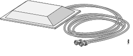
This document outlines the specifications and description of the 2-dBi diversity omnidirectional ceiling mount antenna. This antenna operates in the 2400 - 2500 MHz band and is designed for use where an unobtrusive ceiling mounted antenna is required. The antenna is compatible with Cisco Aironet radio products utilizing a reverse-polarity threaded naval connector (RP-TNC) connector.
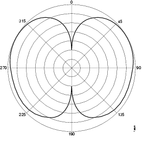
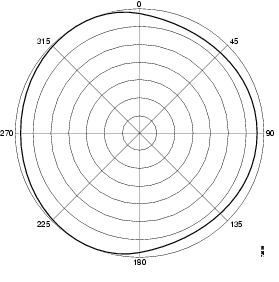
Technical Specifications
System Requirements
A 2.4-GHz Cisco device that utilizes a RP-TNC connector.
Installation Notes
Because antennas transmit and receive radio signals, they are susceptible to RF obstructions and common sources of interference that can reduce throughput and range of the device to which they are connected. Follow these guidelines to ensure the best possible performance:
•
Mount the antenna to utilize its propagation characteristics. A way to do this is to orient the antenna horizontally as high as possible at or near the center of its coverage area.
Note
•
•
–
–
–
–
–
–
•
•
Installation Notes
This antenna is designed to be mounted indoors on a suspended ceiling track having either flush or recessed mounted ceiling tiles.
Safety Instructions
Follow these safety instructions when installing your antenna.
•
•
•
•
•
•
Installation Instructions
The following sections contain procedures for installing the antenna on a suspended ceiling.
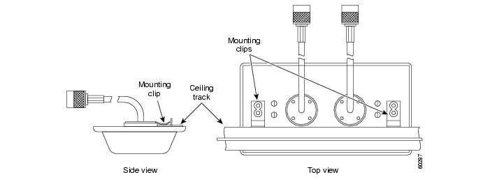
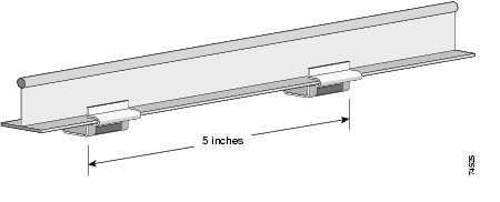
Suspended Ceilings With Flush Mounted Tiles
The antenna is configured to mount to a suspended ceiling track with flush mounted tiles. No modifications are necessary. After you have selected a suitable location, follow these steps to mount your antenna. It may be helpful to examine the illustration below before you install the antennas.
Step 1
Step 2
Step 3
Step 4
Step 5
Note
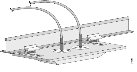
Suspended Ceilings With Recessed Tiles
The antenna can be mounted to a suspended ceiling with recessed tiles by using the provided plastic recessed ceiling mounting clip adapter. After you have selected a suitable location, follow these steps to mount your antenna.
Step 1
Step 2
Step 3
Step 4
Step 5
a.
b.
c.
d.
Step 6
Step 7
Step 8
Note
Obtaining Technical Assistance
Cisco provides Cisco.com as a starting point for all technical assistance. Customers and partners can obtain documentation, troubleshooting tips, and sample configurations from online tools by using the Cisco Technical Assistance Center (TAC) Web Site. Cisco.com registered users have complete access to the technical support resources on the Cisco TAC Web Site.
Cisco.com
Cisco.com is the foundation of a suite of interactive, networked services that provides immediate, open access to Cisco information, networking solutions, services, programs, and resources at any time, from anywhere in the world.
Cisco.com is a highly integrated Internet application and a powerful, easy-to-use tool that provides a broad range of features and services to help you to
•
•
•
•
•
You can self-register on Cisco.com to obtain customized information and service. To access Cisco.com, go to the following URL:
Technical Assistance Center
The Cisco TAC is available to all customers who need technical assistance with a Cisco product, technology, or solution. Two types of support are available through the Cisco TAC: the Cisco TAC Web Site and the Cisco TAC Escalation Center.
Inquiries to Cisco TAC are categorized according to the urgency of the issue:
•
•
•
•
Which Cisco TAC resource you choose is based on the priority of the problem and the conditions of service contracts, when applicable.
Cisco TAC Web Site
The Cisco TAC Web Site allows you to resolve P3 and P4 issues yourself, saving both cost and time. The site provides around-the-clock access to online tools, knowledge bases, and software. To access the Cisco TAC Web Site, go to the following URL:
All customers, partners, and resellers who have a valid Cisco services contract have complete access to the technical support resources on the Cisco TAC Web Site. The Cisco TAC Web Site requires a Cisco.com login ID and password. If you have a valid service contract but do not have a login ID or password, go to the following URL to register:
http://www.cisco.com/register/
If you cannot resolve your technical issues by using the Cisco TAC Web Site, and you are a Cisco.com registered, you can open a case online by using the TAC Case Open tool at the following URL:
http://www.cisco.com/tac/caseopen
If you have Internet access, it is recommended that you open P3 and P4 cases through the Cisco TAC Web Site.
Cisco TAC Escalation Center
The Cisco TAC Escalation Center addresses issues that are classified as priority level 1 or priority level 2; these classifications are assigned when severe network degradation significantly impacts business operations. When you contact the TAC Escalation Center with a P1 or P2 problem, a Cisco TAC engineer will automatically open a case.
To obtain a directory of toll-free Cisco TAC telephone numbers for your country, go to the following URL:
http://www.cisco.com/warp/public/687/Directory/DirTAC.shtml
Before calling, please check with your network operations center to determine the level of Cisco support services to which your company is entitled; for example, SMARTnet, SMARTnet Onsite, or Network Supported Accounts (NSA). In addition, please have available your service agreement number and your product serial number.
Copyright © 2002, Cisco Systems, Inc.
All rights reserved.
![]()
![]()
![]()
![]()
![]()
![]()
![]()
![]()
Posted: Mon Oct 31 12:18:52 PST 2005
All contents are Copyright © 1992--2005 Cisco Systems, Inc. All rights reserved.
Important Notices and Privacy Statement.