|
|

Table Of Contents
Cisco Catalyst 6500 Series Wireless LAN Services Module (WLSM) Deployment Guide
Configure Communications between the Supervisor 720 and WLSM
Configure mGRE Tunnels on the Supervisor 720
Configure the RADIUS Server for LEAP Authentication
IP Addressing for Mobile Clients
Access Point Configuration - Single Encryption Scheme
Access Point Configuration - Multiple Encryption Scheme
Cisco Catalyst 6500 Series Wireless LAN Services Module (WLSM) Deployment Guide
Contents
This Guide provides information and procedures for configuring and deploying the Wireless LAN Services Module (WLSM). The document contains the following information:
Layer 3 Mobility Overview
Mobility in a wireless LAN environment can present a challenge as the physical reach of the network grows. Applications such as voice require sub-150 ms roam times and expect IP address continuity regardless of the Layer 3 boundaries that are crossed. Deploying a sprawling Layer 2 network can subject user traffic to delays and loss of service due to issues such as broadcast storms and Spanning Tree Protocol (STP) reconvergence times.
Layer 3 mobility provides a better performing and more scalable approach. Access points may be deployed in any location in a large Layer 3 network without requiring a single VLAN to be carried throughout the wired switch infrastructure. An overlay of multipoint GRE (mGRE) tunnels allows clients to roam to other access points residing on different Layer 3 subnets without loss of connectivity or a change in IP addressing.
The Cisco Layer 3 mobility solution consists of various hardware and software components. For more information about the Cisco wireless solution go to cisco.com:
http://cisco.com/en/US/products/hw/wireless/index.html
The three primary devices are as follows:
•
Cisco Aironet 1100, 1130AG, 1200, and 1240AG Series Access Points and Cisco Aironet 1300 Series Outdoor Access Point/Bridge
•
•
The software component that provides coordination between these devices and the mobile nodes using its services is called the Wireless Domain Services (WDS). The WDS runs on the WLSM. Each of these components must be configured to work together as a unified system.
Configuring Layer 3 mobility requires linkage between different hardware and software components, and is best accomplished by separating the functional components into modules, configuring each module individually, and verifying that each module works properly before proceeding to the next.
Figure 1 provides an overview of components that make up the Layer 3 mobility solution.
Figure 1 Layer 3 Mobility Components
mGRE Tunnels
The infrastructure that enables Layer 3 mobility consists of Multipoint Generic Routing Encapsulation (mGRE) tunnels. Each tunnel has a single termination point on the Supervisor 720 module of the Catalyst 6500 that hosts the WLSM. The other logical endpoint of the tunnel exists on all access points participating in the Layer 3 mobility network. Clients that associate to a participating access point associate to a particular SSID. The SSID is mapped (either statically or dynamically, via RADIUS) to a mobility network that tunnels all client traffic to the Catalyst 6500. The Supervisor 720 maintains a database of the clients (mobile nodes) and the access points to which they are associated. Roaming from one access point to another simply requires updating the database and changing the forwarding information for that mobile node.
WDS
The WDS software provides a control mechanism for wireless clients that roam between access points residing on different layer 3 subnets.
When WDS is in the WLSM, the access points providing Layer 3 mobility must register with the WDS before wireless clients are given access to the mobility network. The location of the WDS is specified in each access point along with LEAP device credentials that are required for authentication with the WDS. Once the access point is authenticated, it is considered registered. A registered access point is provided with the information needed to build mGRE tunnels to the Supervisor module in the Catalyst 6500.
Configuration Overview
Setting up Layer 3 mobility consists of six basic steps:
1.
2.
3.
4.
5.
6.
Verify Hardware and Software
Before configuring Layer 3 mobility, be sure to verify proper operation of the hardware components and ensure that all equipment is running at the appropriate revisions of software including the following:
•
•
•
•
•
Hardware Components
The Catalyst 6500 that houses the WLSM must use the Supervisor 720 module. Note that all Catalyst 6500 chassis except the Catalyst 6503 require the fan tray 2 module, which in turn requires the 2500W power supply for proper operation. For planning purposes, be aware that the 2500W power supplies use a 20 amp circuit with a NEMA plug.
In the current configuration, the WLSM module is present in slot 1. Before proceeding with any configuration, ensure that the module is recognized. The Status LED should be solid green. If the LED is not solid green, the Supervisor 720 may not be running a version of code that recognizes the WLSM, or there may be a hardware problem with the module.
In the show module display below, note that the WLSM module in slot 1 is recognized by the Supervisor module and has passed diagnostics.
Sup720...#show moduleMod Ports Card Type Model Serial No.--- ----- -------------------------------------- ------------------ -----------1 1 Wireless LAN Service Module WS-SVC-WLAN-1-K9 SAD0805032J2 8 8 port 1000mb GBIC Enhanced QoS WS-X6408A-GBIC SAL05073UXR3 48 48 port 10/100 mb RJ45 WS-X6348-RJ-45 SAD05090C876 2 Supervisor Engine 720 (Active) WS-SUP720-BASE SAD0802089EMod MAC addresses Hw Fw Sw Status--- ---------------------------------- ------ ------------ ------------ -------1 0003.feae.3388 to 0003.feae.338f 3.0 7.2(1) 1.1(1) Ok2 0002.fc45.e480 to 0002.fc45.e487 2.0 5.4(2) 8.3(0.156)RO Ok3 0002.fc26.ea24 to 0002.fc26.ea53 2.0 5.4(2) 8.3(0.156)RO Ok6 000d.6535.ff20 to 000d.6535.ff23 3.0 7.7(1) 12.2(ROCKIES OkMod Sub-Module Model Serial Hw Status--- --------------------------- ------------------ ------------ ------- -------3 Inline Power Module WS-F6K-PWR 1.0 Ok6 Policy Feature Card 3 WS-F6K-PFC3A SAD07520036 2.0 Ok6 MSFC3 Daughterboard WS-SUP720 SAD080302DY 2.0 OkMod Online Diag Status--- -------------------1 Pass2 Pass3 Pass6 PassSup720...#Software Components
The minimum software revisions for Layer 3 mobility support are listed in Table 1. However, Cisco recommends using the most current software releases.
Note
Configure Communications between the Supervisor 720 and WLSM
The WLSM and the Supervisor 720 must define a common VLAN used to communicate with the outside world. Once the VLAN is configured and tested, enable Layer 3 mobility as shown in the following Cisco IOS scripts:
On the Supervisor 720
! --Create the VLAN shared by the WLSM and the Supervisor 720.Sup720...(config)# vlan 100! --Configure the VLAN interface.Sup720...(config)# interface Vlan100! --Assign an appropriate IP address and subnet mask for VLAN 100Sup720...(config-if)# ip address 10.0.100.1 255.255.255.0Sup720...(config-if)# exit! --Specify that this VLAN should be used to communicate with the! -- WLSM (residing in slot 1 in this particular chassis)Sup720...(config)# wlan module 1 allowed-vlan 100On the WLSM:
WLSM...# config t! --Create a VLAN that will be shared by the WLSM and Supervisor 720WLSM...(config)# wlan vlan 100!! --Assign a unique IP address and appropriate subnet maskWLSM...(config-vlan)# ipaddr 10.0.100.2 255.255.255.0!! --Define a default gateway used to direct the WLSM's traffic to the! --Supervisor module by providing the Supervisor's IP address on this! --VLAN as the WLSM's GatewayWLSM...(config-vlan)# gateway 10.0.100.1!! --Specify "admin" for this VLAN to turn on L3 Mobility and start the WDS! --processWLSM...(config-vlan)# adminThe following show command indicates that the Supervisor 720 module is communicating with the WLSM module.
Sup720...#show mobility statusWLAN Module is located in Slot: 1 (HSRP State: Not Applicable)LCP Communication status : upMAC address used for Proxy ARP: 0005.5f54.5800Number of Wireless Tunnels : 2Number of Access Points : 5Number of Mobile Nodes : 1Wireless Tunnel Bindings:Src IP Address Wireless Network-ID Trusted Broadcast--------------- ------------------- ------- ---------10.80.0.1 100 Yes Yes10.80.0.2 101 Yes YesFrom the WLSM, LCP link status should be up and the WDS process should be ACTIVE:
WLSM...#sh wlccp wdsMAC: 0060.2f30.a85b, IP-ADDR: 10.0.100.2State: Administratively StandAlone - ACTIVEAP Count: 3 , MN Count: 2LCP Link status: upHSRP state: Not ApplicableWLSM...#With both modules configured, test the connection between the two devices.
From the WLSM to the Supervisor 720:
WLSM...#ping 10.0.100.2Type escape sequence to abort.Sending 5, 100-byte ICMP Echos to 10.0.100.2, timeout is 2 seconds:!!!!!Success rate is 100 percent (5/5), round-trip min/avg/max = 1/1/1 msFrom the Supervisor 720 to the WLSM:
Sup720...#ping 10.0.100.1Type escape sequence to abort.Sending 5, 100-byte ICMP Echos to 10.0.100.1, timeout is 2 seconds:!!!!!Success rate is 100 percent (5/5), round-trip min/avg/max = 1/1/1 msSup720...#Configure mGRE Tunnels on the Supervisor 720
One mGRE tunnel must be defined on the Supervisor 720 module for each mobility group. A mobility group is a group of wireless clients that are grouped together for some shared characteristic such as a common authentication or encryption scheme, or service such as Voice over IP (VoiP), or user types such as visitors and employees. Settings defined within the tunnel are dynamically pushed to the access points participating in Layer 3 mobility.
The following configuration illustrates a single tunnel setup using the arbitrary tunnel number 100:
! --Begin by defining a unique loopback interface for each tunnel.! --It is important to note that each tunnel requires its own loopback! --interface.Sup720...(config)# interface Loopback100!! --Assign an IP address and subnet mask to be used as the tunnel's! --source address. Note that this is different from the addresses that will! --be assigned to wireless clients and to the tunnel.Sup720...(config-if)# ip address 10.80.0.1 255.255.255.255!! --Define the tunnel interfaceSup720...(config-if)# interface Tunnel100!! --Assign an IP Address and subnet mask appropriate to the tunnel.! --This address will be used as the default gateway for wireless! --clients on this L3 Mobility network.Sup720...(config-if)# ip address 172.16.1.1 255.255.255.0!! --Tie the tunnel to the loopback interface.Sup720...(config-if)# tunnel source Loopback100!! --Enable mGRE on this tunnelSup720...(config-if)# tunnel mode gre multipoint!! --The mobility network-id defines this as a unique mobility network.! --The network-id defined for this tunnel will also be defined under one of! --the access point's SSID definitions to identify its participation in this! --Layer 3 Mobility network.mobility network-id 100The tunnel is now defined and additional items can be configured on the tunnel interface, which include:
interface Tunnel100!! --Use a descriptor to identify the type of clients in this tunneldescription LEAP_wireless_clients!!! --IP Redirects should be disabled (and are disabled by default, so this! --command is only necessary if that default behavior has been changed).no ip redirects!!! --By default, a mobility network is considered "untrusted". In an untrusted! --network, mobile nodes are required to use a DHCP-obtained IP address.! --In a "trusted" network, mobile nodes are allowed to use static IP! --addresses. The following command allows static IP addressing:mobility trust!!! --Enable DCHP packet snooping. This feature is used by the Supervisor 720! --module to populate the IP addresses of mobile clients in the Forwarding! --Information Base when the network is considered "untrusted". (Trusted! --networks obtain IP addressing by snooping IP packets generated by a! --mobile node). Note that the corresponding global command "ip dhcp! --snooping" is also required when using an untrusted network.ip dhcp snooping packets!!! --By default, broadcasts are received, but not forwarded on a tunnel! --interface. This behavior can be enabled on a per-tunnel basis.mobility broadcast!!! --If a mobility network uses a DHCP server that is not resident on! --the Supervisor 720, configure a helper-address to convert the! --DHCP requests from broadcast to unicast directed to the DHCP server.ip helper-address 10.91.104.76
Note
Sup720...#show interface tunnel 100Tunnel100 is up, line protocol is upHardware is TunnelDescription: To_wireless_clientsInternet address is 172.16.1.1/24MTU 1514 bytes, BW 9 Kbit, DLY 500000 usec,reliability 255/255, txload 1/255, rxload 1/255Encapsulation TUNNEL, loopback not setKeepalive not setTunnel source 10.80.0.1 (Loopback100), fastswitch TTL 255Tunnel protocol/transport multi-GRE/IP, key disabled, sequencing disabledChecksumming of packets disabled, fast tunneling enabledLast input 00:00:00, output 00:00:00, output hang neverLast clearing of "show interface" counters neverInput queue: 0/75/0/0 (size/max/drops/flushes); Total output drops: 0Queueing strategy: fifoOutput queue: 0/0 (size/max)5 minute input rate 0 bits/sec, 0 packets/sec5 minute output rate 0 bits/sec, 0 packets/secL2 Switched: ucast: 0 pkt, 0 bytes - mcast: 0 pkt, 0 bytesL3 in Switched: ucast: 0 pkt, 0 bytes - mcast: 0 pkt, 0 bytes mcastL3 out Switched: ucast: 0 pkt, 0 bytes mcast: 0 pkt, 0 bytes178707 packets input, 19823493 bytes, 0 no bufferReceived 0 broadcasts, 0 runts, 0 giants, 0 throttles0 input errors, 0 CRC, 0 frame, 0 overrun, 0 ignored, 0 abort102869 packets output, 10834504 bytes, 0 underruns0 output errors, 0 collisions, 0 interface resets0 output buffer failures, 0 output buffers swapped outVerify that the mobility network is up and running with the correct parameters.
Sup720...#sho mobility network 100Wireless Network ID : 100Wireless Tunnel Source IP Address : 10.80.0.1Wireless Network Attributes : Trusted, Brodcast EnabledWireless Network State : UpRegistered Access Point on Wireless Network 100:AP IP Address AP Mac Address Wireless Network-ID--------------- -------------- -------------------10.10.0.29 0005.9a39.aeba 100 0Registered Mobile Nodes on Wireless Network 100:MN Mac Address MN IP Address AP IP Address Wireless Network-ID-------------- --------------- --------------- -------------------0006.d786.3842 172.16.1.24 10.10.0.29 100Sup720...#For a global view of all tunnels configured on this Supervisor module, use the show mobility command:
Sup720...#show mobility statusWLAN Module is located in Slot: 1 (HSRP State: Not Applicable)LCP Communication status : upMAC address used for Proxy ARP: 0005.5f54.5800Number of Wireless Tunnels : 2Number of Access Points : 1Number of Mobile Nodes : 1Wireless Tunnel Bindings:Src IP Address Wireless Network-ID Trusted Broadcast--------------- ------------------- ------- ---------10.80.0.1 100 Yes Yes10.80.0.2 101 Yes Yes
Note
!router eigrp 100redistribute connectednetwork 10.91.104.0 0.0.0.255network 172.16.0.0auto-summary!The routing table that should reflect routes for the networks/interfaces used and should advertise them so that other devices will know how to reach them and the tunnels that they represent.
Sup720...#show ip route172.16.0.0/16 is variably subnetted, 3 subnets, 2 masksD 172.16.0.0/16 is a summary, 6d18h, Null0C 172.16.1.0/24 is directly connected, Tunnel100C 172.16.2.0/24 is directly connected, Tunnel101D 10.0.0.0/8 is a summary, 6d18h, Null0D 10.18.0.0/24 [90/28416] via 10.91.104.69, 21:21:59, Vlan1D 10.19.0.0/24 [90/28416] via 10.91.104.69, 21:22:02, Vlan1D 10.16.0.0/24 [90/28416] via 10.91.104.69, 21:22:02, Vlan1D 10.17.0.0/24 [90/28416] via 10.91.104.69, 21:22:02, Vlan1D 10.50.10.0/24 [90/281856] via 10.91.104.90, 6d18h, Vlan1D 10.91.96.100/30 [90/3072] via 10.91.104.65, 6d18h, Vlan1C 10.80.0.2/32 is directly connected, Loopback101C 10.80.0.1/32 is directly connected, Loopback100C 10.0.100.0/24 is directly connected, Vlan100C 10.91.104.64/26 is directly connected, Vlan1S* 0.0.0.0/0 [1/0] via 10.91.104.65Cisco recommends that the tunnel interfaces be configured as passive interfaces so as not to propagate unnecessary routing traffic over the tunnels (such as passive-interface tunnel100).
Configure the RADIUS Server for LEAP Authentication
In the Cisco wireless solution, infrastructure devices (access points) and the WLSE establish secure communications with the WDS using LEAP authentication. Before access points and the WLSE can authenticate to the WDS, the CiscoSecure ACS server or third-party LEAP-compliant server (such as Funk Software or Interlink) must be configured.
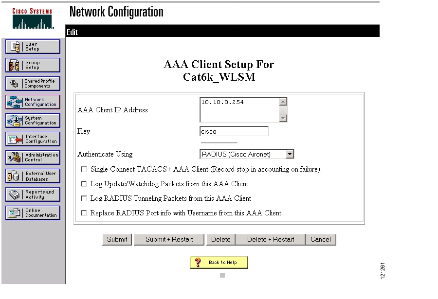
The WLSM must be defined on the RADIUS server as an AAA Client, which allows the WLSM to make requests to authenticate the LEAP credentials of registering devices. Using the CiscoSecure ACS RADIUS server, select Network Configuration, define the IP address of the WDS and the shared RADIUS key, and specify Radius (Cisco Aironet) as the authentication type as shown in Figure 2.
Figure 2 Defining the WDS on the AAA Server
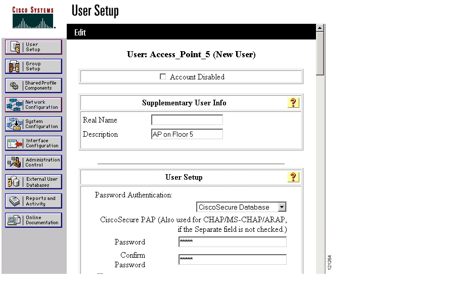
Devices such as access points that participate in Layer 3 mobility must have their LEAP credentials defined on the RADIUS server as shown in Figure 3. Configure each device by selecting the User Setup tab. Define the name for the device (as specified on the access point or WLSE) and specify that this user's authentication credentials must be checked against the CiscoSecure database. Complete the entry by configuring the password for this user. You can use this entry for a single access point or for a number of access points in the network.
Figure 3 Defining the Users on the AAA Server
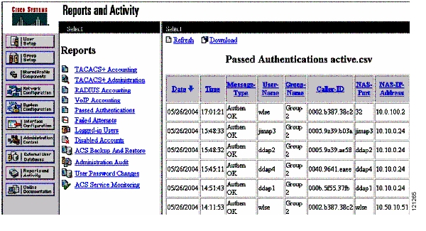
Troubleshooting authentication problems may require the use of the Reports and Activity log on the ACS server. Check the passed attempts ( Figure 4) and failed attempts ( Figure 5) for requests being sourced by the WDS (which appear as the NAS on the ACS server).
Figure 4 AAA Server —Passed Attempts
Figure 5 AAA Server—Failed Attempts
Configure the WDS on the WLSM
Configure Communications from the WDS to the RADIUS Server
Configuring the WDS to communicate with the RADIUS requires the following steps detailed in a show run command:
aaa new-model!! --Define a group used to authenticate LEAP devicesaaa authentication login leap-devices group radius!! --Define the RADIUS server used to LEAP-authenticate devicesradius-server host 10.91.104.76 auth-port 1645 acct-port 1646radius-server key cisco!! --Configure the WDS to use the defined authentication groupwlccp authentication-server infrastructure leap-devices!Configure Pass-Through Client Authentication
Access points registered with a WDS no longer communicate directly with a RADIUS server to authenticate 802.1X wireless clients. Once an access point registers with the WDS, it funnels all subsequent registrations through the WDS whether they are infrastructure authentications performed as part of the device's WDS re-registration or client authentications performed as part of a client's association to the access point.
The WDS must be configured to pass client authentications through to a RADIUS server. Without this configuration, client authentications will fail and clients will be unable to associate to the access point.
The following script shows how to configure the WLSM running the WDS to enable client authentication pass-thru:
!aaa new-model!! --Define a group used to authenticate client devicesaaa authentication login client-authentication group radius!! --Define the RADIUS server used for the client groupradius-server host 10.91.104.76 auth-port 1645 acct-port 1646radius-server key cisco!! --Point the AP to the AAA group used for client authenticationwlccp authentication-server client any client-authentication! --Note that the client authentication can be configured for specific! --802.1x authentication types by replacing "any" with the desired! --authentication typeAuthentication messages flow from the access point to the WDS and from the WDS to the RADIUS server. The RADIUS server approves or rejects the device credentials and replies to the WDS. The WDS will pass the RADIUS server's reply to the access point. When debugging, check that each step in the process completes without failure. On the WDS, run one or more of the following debugs to assist in troubleshooting client authentication through the WDS:
WLSM...#debug wlccp wds ?aggregator Radio measurement(rm) aggregatorautenticator MAC and EAP authenticatormobility Layer-3-Mobilitynm Network Managementstate WDS fsm state transitionsstatistics WDS statisticsConfigure an Access Point
Register with the WDS
The first configuration task on an access point is to enter LEAP credentials so that it can register with the WDS. Access points can be configured through the access point's web-based interface, the access point's CLI, or through a WLSE configuration job. The web interface and CLI are detailed here. For details on configuring access points using WLSE, refer to the following link:
Follow these steps to register an access point with the WDS:
Step 1
Step 2
Step 3
Note
Step 4
Step 5
Note
Step 6
Step 7
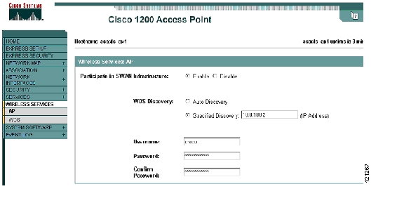
Figure 6 illustrates the configuration parameters.
Figure 6 Access Point—Participating in the Cisco Wireless Solution
To configure the same items through the Cisco IOS command line interface, enter the following commands:
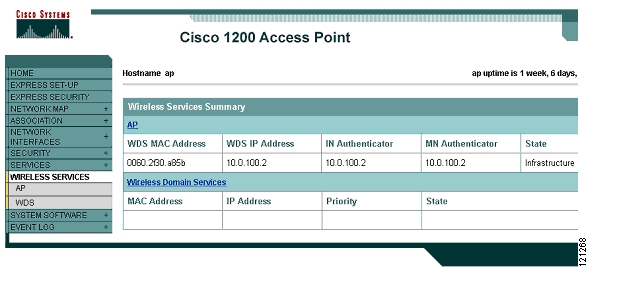
! --Enter the LEAP credentialswlccp ap username cisco password 7 14141B180F0B! --Specify the IP address of the WDSwlccp ap wds ip address 10.0.100.2!The access point attempts to register with the WDS. Figure 8 shows a properly registered access point.
Figure 7 Access Point—Registered With WDS
The WDS portion of the access point configuration is complete.
Mobility Tunnel Assignment
In order for mobile clients to associate to an access point, become registered mobile nodes, obtain an IP address, and be allowed to pass traffic on a Layer 3 Mobility tunnel, linage must be made between the RF side (SSID) and the tunnel side (mobility network id). This linkage may be accomplished either dynamically by using RADIUS authentication or by using access point configuration of a default mobility tunnel per SSID. Specifying the mobility network-id as part of the SSID definition places all traffic from clients associated to that SSID into the corresponding tunnel, unless the client is dynamically assigned to an alternative mobility tunnel using RADIUS.
Note
Link SSIDs with Mobility Tunnels - Single Encryption Scheme
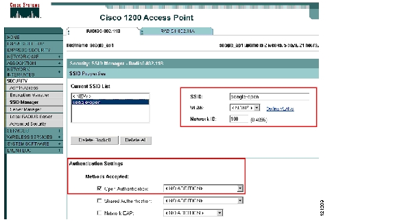
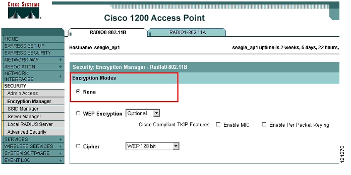
The simplest of configurations involves a single SSID with open authentication and no encryption as shown in Figure 8 and Figure 9.
Figure 8 Access Point—Open Authentication SSID With Mobility Network ID
Figure 9 Access Point—Open SSID With No Encryption
The Network ID in Figure 8 specifies the mobility network that maps to this newly-defined SSID. The following script shows the IOS configuration process:
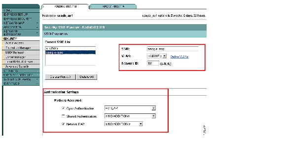
!interface Dot11Radio0no ip addressno ip route-cache!ssid seagle-openauthentication openmobility network-id 100!Rather than being open, an SSID could be configured for some form of authentication and encryption as shown in Figure 10 and Figure 11.
Figure 10 Access Point—Mobility Network Configured for LEAP Authentication
Figure 11 Access Point—Mobility Network Configured for Dynamic WEP
The script below shows the Cisco IOS configuration process:
interface Dot11Radio0no ip addressno ip route-cache!encryption mode ciphers ckip!ssid seagle-leapauthentication open eap eap_methodsauthentication network-eap eap_methodsmobility network-id 101!Once configured, a client attempting to associate to the defined SSID is authenticated and added to the mobility group. To check for a successful client association, use the show command:
Seagle_ap1# show wlccp ap mobility forwardingWireless Control(0005.5f54.5800) IPv4 Forwarding TableMAC Address IP address Tunnel address0002.8aa3.24c0 172.16.1.22 10.80.0.1Seagle_ap1# show wlccp ap mnMAC Address IP address VLAN Network ID0002.8aa3.24c0 172.16.1.11 4001 (Dynamic) 100 (Radius Assigned)On the Supervisor 720, check for registered mobile nodes:
Sup720...#show mobility mnMN Mac Address MN IP Address AP IP Address Wireless Network-ID-------------- --------------- --------------- -------------------0002.8aa3.24c0 172.16.1.22 10.91.104.108 100Additional SSIDs may be added to this radio's configuration but, because encryption is defined under the radio interface and not under the individual SSIDs, they must all use the same encryption scheme. To configure multiple mobility groups using different encryption schemes requires the configuration of VLANs on the access point. These VLANs are only locally significant, meaning the Fast Ethernet side of the access point does not need to be configured as an 802.1q trunk (unless there is a need to configure more than one locally bridged VLAN as in the case of IP multicast traffic).
Link SSIDs with Mobility Tunnels - Multiple Encryption Schemes
In order to support multiple encryption schemes for multiple mobility networks on the access point, VLANs must be configured. However, these VLANs are only locally significant and are not trunked to the attached Ethernet switch. This configuration may also be used in conjunction with dynmaic mobility group assignment to permit mixing encryption types. Configuring this arrangement on the CLI can be error-prone since many line items must be duplicated on both the radio interfaces and the Fast Ethernet interfaces. Cisco recommends that you perform the configuration using the GUI. When the configuration is complete, use the CLI to view it.
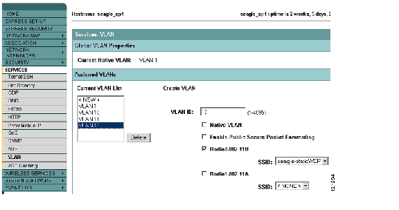
In the sample configuration, since the native VLAN is the only defined VLAN that is not tied to a mobility network-id, the upstream switch does not need to be configured as a trunk. The VLAN definitions are made solely for the convenience of creating mobility groups with separate encryption schemes and therefore do not need to trunked. If more than one defined VLAN is not tied to a mobility network (that is, its traffic is locally bridged), the Fast Ethernet interface must be configured as an 802.1q trunk and those specific VLANs must be supported on the attached switch interface. Traffic generated as part of a mobility network is sent over the native VLAN. To configure multiple encryption schemes, begin by defining a VLAN for each encryption type to be used and a native VLAN as shown in Figure 12.
Figure 12 Access Point—Defining VLANs
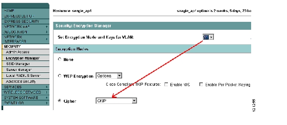
The next step is to define the encryption protocol used by each VLAN as shown in Figure 13.
Figure 13 Access Point—Defining Per VLAN Encryption
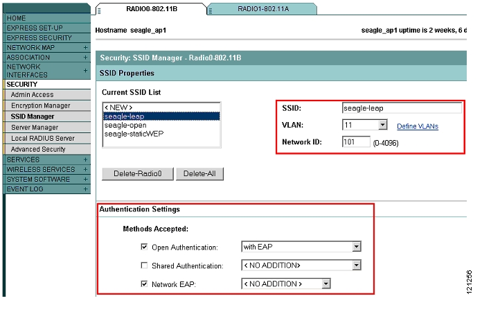
The last step is to assign SSIDs with mobility network-IDs and any authentication settings and map them to VLANs as shown in Figure 14.
Note
Figure 14 Access Point—Defining SSIDs With Mobility Network IDs
Review the configuration on the CLI as shown in the following script:
interface Dot11Radio0no ip addressno ip route-cache!! --Of the mobility networks that will use encryption, configure encryption types:encryption vlan 11 mode ciphers ckipencryption vlan 12 key 2 size 128bit 7 320E1C172908192BDC1668324160 transmit-keyencryption vlan 12 mode wep mandatory!! --Define each SSID and specify a VLAN, authentication, and mobility network ID.!!! --SSID "seagle-leap" uses LEAP authentication with a CKIP cipherssid seagle-leapvlan 11authentication open eap eap_methodsauthentication network-eap eap_methodsmobility network-id 101!! --SSID "seagle-open" uses open authentication and no encryptionssid seagle-openvlan 10authentication openmobility network-id 100!! --SSID "seagle-staticWEP" uses Open Authentication and a 128 bit static WEP keyssid seagle-staticWEPvlan 12authentication openmobility network-id 102!speed basic-1.0 basic-2.0 basic-5.5 basic-11.0rts threshold 2312station-role root!! --Radio subinterfaces are automatically created for each defined VLAN.! --The native VLAN (a "locally bridged" VLAN) carries! --administrative traffic and mGRE tunneled traffic to the upstream switchinterface Dot11Radio0.1encapsulation dot1Q 1 nativeno ip route-cachebridge-group 1bridge-group 1 subscriber-loop-controlbridge-group 1 block-unknown-sourceno bridge-group 1 source-learningno bridge-group 1 unicast-floodingbridge-group 1 spanning-disabled!interface Dot11Radio0.10encapsulation dot1Q 10no ip route-cachebridge-group 10bridge-group 10 subscriber-loop-controlbridge-group 10 block-unknown-sourceno bridge-group 10 source-learningno bridge-group 10 unicast-floodingbridge-group 10 spanning-disabled!interface Dot11Radio0.11encapsulation dot1Q 11no ip route-cachebridge-group 11bridge-group 11 subscriber-loop-controlbridge-group 11 block-unknown-sourceno bridge-group 11 source-learningno bridge-group 11 unicast-floodingbridge-group 11 spanning-disabled!interface Dot11Radio0.12encapsulation dot1Q 12no ip route-cachebridge-group 12bridge-group 12 subscriber-loop-controlbridge-group 12 block-unknown-sourceno bridge-group 12 source-learningno bridge-group 12 unicast-floodingbridge-group 12 spanning-disabled!interface Dot11Radio1no ip addressno ip route-cachespeed basic-6.0 9.0 basic-12.0 18.0 basic-24.0 36.0 48.0 54.0rts threshold 2312station-role rootbridge-group 1bridge-group 1 subscriber-loop-controlbridge-group 1 block-unknown-sourceno bridge-group 1 source-learningno bridge-group 1 unicast-floodingbridge-group 1 spanning-disabled!interface FastEthernet0no ip addressno ip route-cacheduplex autospeed auto!! --Subinterfaces are also created on the wired side for every VLANinterface FastEthernet0.1encapsulation dot1Q 1 nativeno ip route-cachebridge-group 1no bridge-group 1 source-learningbridge-group 1 spanning-disabled!interface FastEthernet0.10encapsulation dot1Q 10no ip route-cachebridge-group 10no bridge-group 10 source-learningbridge-group 10 spanning-disabled!interface FastEthernet0.11encapsulation dot1Q 11no ip route-cachebridge-group 11no bridge-group 11 source-learningbridge-group 11 spanning-disabled!interface FastEthernet0.12encapsulation dot1Q 12no ip route-cachebridge-group 12no bridge-group 12 source-learningbridge-group 12 spanning-disabled!interface BVI1ip address 10.91.104.108 255.255.255.192no ip route-cache!ip default-gateway 10.91.104.65ip http serverip http help-path http://www.cisco.com/warp/public/779/smbiz/prodconfig/help/eag/122-15.JA/1100ip radius source-interface BVI1bridge 1 route ip!!wlccp ap username cisco password 7 045802150C2Ewlccp ap wds ip address 10.0.100.2wlccp ap mobility!line con 0line vty 0 4login localline vty 5 15login!endIn the above configuration, the Fast Ethernet switch port that the access point attaches to does not need to be configured as an 802.1q trunk because only one locally bridged VLAN is present. However it may be necessary to configure the Fast Ethernet interface on the attached switch as an 802.1q trunk if more than one VLAN is configured and not tied to a mobility network.
Additional Considerations
IP Addressing for Mobile Clients
Devices that associate to an SSID mapped to a mobility network have either a statically defined IP address or will use DHCP (Dynamic Host Control Protocol) to obtain an address.
One of the optional commands within a tunnel configuration is the mobility trust command. This command allows client devices to pass traffic using a statically assigned IP address. The global form of this command is:
Sup720 (config-if)# mobility trustFor security reasons, it is recommended that mobile devices be assigned an IP address by a DHCP server. The DHCP server can reside on the Supervisor 720 or elsewhere on the network. For a DHCP server on the Supervisor module, use the following example to configure the server.
ip dhcp excluded-address 172.16.1.0 172.16.1.20ip dhcp excluded-address 172.16.2.0 172.16.2.20!ip dhcp pool mobilenet1network 172.16.1.0 255.255.255.0default-router 172.16.1.1!ip dhcp pool mobilenet2network 172.16.2.0 255.255.255.0default-router 172.16.2.1!Also, a global command, ip dhcp snooping is required for dhcp snooping. This command is used to reveal IP address assignments of mobile nodes and must be set globally as well as on a tunnel basis. The global form of the command is:
Sup720...(config)# ip dhcp snoopingFor DHCP servers residing on a router other than the Supervisor 720, be sure to use an IP Helper Address on the tunnel configuration. The helper address takes a broadcast request for an address from the client and unicasts it to the DHCP server.
Deployments that use DHCP-assigned addressing may implement a feature known as Option 82. For interfaces that employ DHCP Snooping, Option 82 provides information back to the DHCP server detailing the Switch, Module, and Port to which the address was assigned. While this is a useful feature for client tracking purposes, it is not supported on the tunnel interfaces used for Layer 3 Mobility.
If this option is enabled on the DHCP server, an administrator may see that IP addresses are handed out by the DHCP server, but never reach the mobile node. Static IP addressing (with the "trust" command on the tunnel interface) is not affected by this issue so if static IP addresses work, but DHCP does not, then Option 82 might be the problem. Running a debug on the Supervisor 720 (debug ip dhcp snooping packets) will also reveal Option 82 as the cause of the problem.
To resolve this issue, run the following command from the global configuration prompt:
Sup720...>(config)# no ip dhcp snooping information optionThis command is global, but will only turn off Option 82 for interfaces running DHCP Snooping (which will be all tunnel interfaces for Layer 3 Mobility).
Fast Secure Roaming
The fast secure roaming feature enables wireless clients to quickly roam between access points residing on the same subnet. Using CCKM (Cisco Centralized Key Management), the WDS caches security keys derived for a client's session and provides them to a destination access point when a client roams. By caching this information rather than forcing the client to reauthenticate to a centralized server, the authentication time is lessened and the total time required to roam is reduced.
Fast secure roaming works at Layer 2. Fast secure roaming also works over Layer 3 mobility because the mGRE tunnel architecture creates a virtual subnet. All access points participating in a particular mobility network support clients on a single subnet. The WLSM provides the WDS for that subnet and caches the security credentials for its mobile clients.
To enable Fast Secure Roaming on an SSID using the GUI, configure the access point as shown in Figure 15.
Figure 15 Access Point—Configuring Fast Secure Roaming on an SSID
To enable fast secure roaming on an SSID from the CLI, enter the following commands:
ssid seagle-leapvlan 11authentication open eap eap_methodsauthentication network-eap eap_methodsauthentication key-management cckmmobility network-id 101!IP Multicast
The administrative messages in IP Multicast (for example, joins and leaves) are sent over the locally bridged network. The locally bridge network is either the native VLAN or a VLAN created specifically for this purpose.
Actual multicast traffic in the upstream direction (from wireless network to wired), is sent within the tunnel architecture along with unicast and broadcast traffic. In the downstream direction (from wired to wireless), IP multicast traffic is locally bridged. In order to accommodate this traffic, a separate VLAN must be configured for each network with multicast capabilities.
IGMP snooping is introduced on the access points in Cisco IOS Release 12.3(8)JA to permit dynamic creation of the multicast group membership for wireless clients. The upstream router must be configured for multicast routing (i.e., ip pim sparse-dense-mode).
Note
Use the no form of the ip igmp snooping command to disable IGMP snooping.
To verify opertion of IGMP snooping with a multicast-enabled client connected, query the multicast client with the following command:
Seagle ap#show ip igmp trackingIP Multicast Mobility VLAN Host Count------------- -------- ----- ----------224.2.226.53 102 10 10007.0eb9.3d78. Int Do0.10Fragmentation
Tunneling technology is susceptible to fragmentation because of the overhead (an additional 24 bytes per packet) added to a user's data packets as they enter the tunnel. Depending on the size of the packet sent by the client and the IP Maximum Transmission Unit (MTU) of the access point and the Catalyst 6500, traffic may get dropped.
A common issue that may cause traffic to be dropped occurs when a client's MTU is greater than the MTU size of the tunnel and the client's traffic is marked as DF (don't fragment). The receiving device (Catalyst 6500 or access point) must drop the traffic since it cannot add the tunnel header without exceeding the MTU and is not allowed to break the packet into smaller pieces with separate headers.
Note
To test the effect of the MTU on traffic delivery, send 1518 Byte data packets from a wireless client to a wired device across a mobility network. Then send the same size packets in the opposite direction. Investigate the MTU if any of the traffic is dropped.
As a general guideline, the IP MTU should be set to a number less than or equal to the smallest setting on all devices in both the upstream (towards the Catalyst 6500) and downstream (towards the access point) directions minus the tunnel header's extra 24 bytes. Based on a 1500 byte minimum packet size, the recommended IP MTU would be less than or equal to 1476 Bytes. Setting this parameter on the tunnel interface on the Supervisor 720, dynamically passes it to the access point during tunnel setup. The default IP MTU setting is 1476 Bytes. There is no need to modify it unless it has been previously reconfigured. For more information about tunneling and fragmentation refer to Cisco.com:
http://www.cisco.com/warp/public/105/56.html#pfragment.
Configure the WLSE for WDS
The CiscoWorks Wireless LAN Solution Engine (WLSE) provides many features for managing the wireless LAN, including the following:
•
•
•
•
For some features, such as RF management, the WLSE collects information from access points and clients throughout the network. In order to receive RF management information, the WLSE must be registered with the WDS in the same way that an access point must be registered with the WDS in order to provide it.
In order for the WLSE to communicate with WDS, the following configurations must be present:
•
•
•
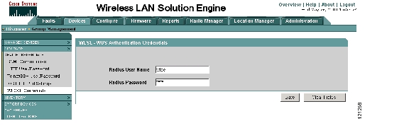
The first of these configurations involves browsing to the WLSE and selecting WLCCP Credentials under the Discover section of the Devices tab as shown in Figure 16.
Figure 16 WLSE—Defining LEAP Credentials
Enter the LEAP username and password pair that the WLSE will pass to the WDS. Be sure that this username/password pair is properly configured as a user in the RADIUS database on the CiscoSecure ACS server.
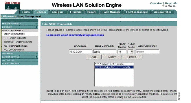
The next step is to manage the WDS from the WLSE. Before a device can be managed by WLSE, both devices must be configured for SNMP. The WLSE is configured as shown in Figure 17.
Figure 17 WLSE—Defining SNMP Attributes
Note
The CLI configuration is as follows:
WLSM...# config tWLSM...(config)# snmp-server view iso iso includedWLSM...(config)# snmp-server community public view iso ROWLSM...(config)# snmp-server community private view iso RWOnce configured, the WDS appears in the device discovery on the WLSE ( Figure 18) and is either automatically managed (if configured to do so) or provides the administrator the option of managing it. With the state of the device as managed, the WLSE attempts to register with the WDS (after the WDS is configured with the IP address of the WLSE server).
Figure 18 WLSE—Verifying WLSM Device Details
On the WDS, specify the IP address of the Wireless Network Manager (WNM). The WNM in the current Cisco wireless solution environment is the WLSE.
The following script shows how to specify the WNM IP address using the CLI:
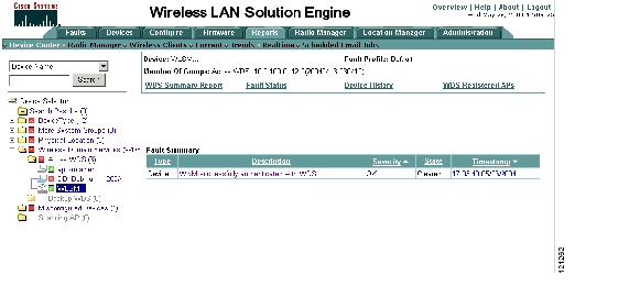
!! --Specify the IP address of the WLSE server to which the WDS will! --communicate for the purposes of Radio Managementwlccp wnm ip address 10.91.104.79!In the Reports section of the Device Manager tab on the WLSE, the WNM should reflect being successfully authenticated with WDS, as shown in Figure 19.
Figure 19 WLSE—Successful WDS Authentication
Configurations
The following sections contain CLI configuration scripts.
WLSM Configuration
WLSM...#sh runBuilding configuration...Current configuration : 1243 bytes!version 12.2no service padservice timestamps debug datetime msecservice timestamps log datetime msecno service password-encryption!hostname WLSM...!logging queue-limit 100enable password rfrus!username admin password 0 ciscospd headroom 512aaa new-model!!aaa authentication login infrastructure-authentication group radiusaaa authentication login client-authentication group radiusaaa session-id commonip subnet-zeroip tftp source-interface Ethernet0/0.100!!wlan vlan 100ipaddr 10.0.100.2 255.255.255.0gateway 10.0.100.1admin!!!!!!ip classlessip route 0.0.0.0 0.0.0.0 10.0.100.1ip http serverno ip http secure-server!no cdp runsnmp-server view iso iso includedsnmp-server community public view iso ROsnmp-server community private view iso RWsnmp-server enable traps ttyradius-server host 10.91.104.76 auth-port 1645 acct-port 1645radius-server key ciscoradius-server authorization permit missing Service-Type!wlccp authentication-server infrastructure infrastructure-authenticationwlccp authentication-server client any client-authenticationwlccp wnm ip address 10.91.104.79!line con 0line 1 3no exectransport input allflowcontrol softwareline vty 0 4password cisco!endWLSM...#Supervisor 720 Configuration
(Line Card Configurations Deleted)
Sup720...#sh runBuilding configuration...Current configuration : 6352 bytes!version 12.2service timestamps debug uptimeservice timestamps log uptimeservice password-encryptionservice counters max age 10!hostname Sup720...!boot system sup-bootflash:s72033-jsvdbg-mz.ROCKIES_SPL_040628logging snmp-authfailenable password 7 04490D141A32!no aaa new-modelwlan module 1 allowed-vlan 100ip subnet-zero!!ip dhcp excluded-address 172.16.1.0 172.16.1.20ip dhcp excluded-address 172.16.2.0 172.16.2.20!ip dhcp pool mobilenet1network 172.16.1.0 255.255.255.0default-router 172.16.1.1!ip dhcp pool mobilenet2network 172.16.2.0 255.255.255.0default-router 172.16.2.1!ip dhcp snoopingmls ip multicast flow-stat-timer 9no mls flow ipno mls flow ipv6mls cef error action freeze!!!!!spanning-tree mode pvstno spanning-tree optimize bpdu transmissiondiagnostic cns publish cisco.cns.device.diag_resultsdiagnostic cns subscribe cisco.cns.device.diag_commands!redundancymode rpr-plusmain-cpuauto-sync running-configauto-sync standard!vlan internal allocation policy ascendingvlan access-log ratelimit 2000!!interface Loopback100description tunnel_sourceip address 10.80.0.1 255.255.255.255!interface Loopback101description tunnel_sourceip address 10.80.0.2 255.255.255.255!interface Tunnel100description To_wireless_clientsip address 172.16.1.1 255.255.255.0no ip redirectsip mtu 1476ip dhcp snooping packetstunnel source Loopback100tunnel mode gre multipointmobility network-id 100mobility trustmobility broadcast!interface Tunnel101description To_wireless_clientsip address 172.16.2.1 255.255.255.0no ip redirectsip dhcp snooping packetstunnel source Loopback101tunnel mode gre multipointmobility network-id 101mobility trustmobility broadcast!! <snip>!interface Vlan1ip address 10.91.104.100 255.255.255.192!interface Vlan100ip address 10.0.100.1 255.255.255.0!router eigrp 100redistribute connectednetwork 10.91.104.0 0.0.0.255network 172.16.0.0auto-summary!ip classlessip route 0.0.0.0 0.0.0.0 10.91.104.65no ip http server!!dial-peer cor custom!!line con 0line vty 0 4password 7 14141B180F0Blogin!endSup720...#Access Point Configuration - Single Encryption Scheme
seagle_ap1#sh runBuilding configuration...Current configuration : 1890 bytes!version 12.2no service padservice timestamps debug datetime msecservice timestamps log datetime msecservice password-encryption!hostname seagle_ap1!logging queue-limit 100enable secret 5 $1$EGx1$d.0irqIr99x5pV4v9yRyG0!username Cisco password 7 070C285F4D06ip subnet-zero!!!bridge irb!!interface Dot11Radio0no ip addressno ip route-cache!encryption mode ciphers ckip!ssid seagle-leapauthentication open eap eap_methodsauthentication network-eap eap_methodsauthentication key-management cckmmobility network-id 100!speed basic-1.0 basic-2.0 basic-5.5 basic-11.0rts threshold 2312station-role rootbridge-group 1bridge-group 1 subscriber-loop-controlbridge-group 1 block-unknown-sourceno bridge-group 1 source-learningno bridge-group 1 unicast-floodingbridge-group 1 spanning-disabled!interface Dot11Radio1no ip addressno ip route-cache!ssid tsunamiauthentication openguest-mode!speed basic-6.0 9.0 basic-12.0 18.0 basic-24.0 36.0 48.0 54.0rts threshold 2312station-role rootbridge-group 1bridge-group 1 subscriber-loop-controlbridge-group 1 block-unknown-sourceno bridge-group 1 source-learningno bridge-group 1 unicast-floodingbridge-group 1 spanning-disabled!interface FastEthernet0no ip addressno ip route-cacheduplex autospeed autobridge-group 1no bridge-group 1 source-learningbridge-group 1 spanning-disabled!interface BVI1ip address 10.91.104.108 255.255.255.192no ip route-cache!ip default-gateway 10.91.104.65ip http serverip http help-path http://www.cisco.com/warp/public/779/smbiz/prodconfig/help/eag/122-15.JA/1100ip radius source-interface BVI1bridge 1 route ip!!wlccp ap username cisco password 7 030752180500wlccp ap wds ip address 10.0.100.2!line con 0line vty 0 4login localline vty 5 15login!endseagle_ap1#Access Point Configuration - Multiple Encryption Scheme
seagle_ap1#sh runBuilding configuration...Current configuration : 3588 bytes!version 12.2no service padservice timestamps debug datetime msecservice timestamps log datetime msecservice password-encryption!hostname seagle_ap1!logging queue-limit 100enable secret 5 $1$EGx1$d.0irqIr99x5pV4v9yRyG0!username Cisco password 7 070C285F4D06ip subnet-zero!!!bridge irb!!interface Dot11Radio0no ip addressno ip route-cache!encryption vlan 11 mode ciphers ckip!encryption vlan 12 key 2 size 128bit 7 320E1C172908192BDC1668324160 transmit-keyencryption vlan 12 mode wep mandatory!ssid seagle-leapvlan 11authentication open eap eap_methodsauthentication network-eap eap_methodsauthentication key-management cckmmobility network-id 101!ssid seagle-openvlan 10authentication openmobility network-id 100!ssid seagle-staticWEPvlan 12authentication openmobility network-id 102!speed basic-1.0 basic-2.0 basic-5.5 basic-11.0rts threshold 2312station-role root!interface Dot11Radio0.1encapsulation dot1Q 1 nativeno ip route-cachebridge-group 1bridge-group 1 subscriber-loop-controlbridge-group 1 block-unknown-sourceno bridge-group 1 source-learningno bridge-group 1 unicast-floodingbridge-group 1 spanning-disabled!interface Dot11Radio0.10encapsulation dot1Q 10no ip route-cachebridge-group 10bridge-group 10 subscriber-loop-controlbridge-group 10 block-unknown-sourceno bridge-group 10 source-learningno bridge-group 10 unicast-floodingbridge-group 10 spanning-disabled!interface Dot11Radio0.11encapsulation dot1Q 11no ip route-cachebridge-group 11bridge-group 11 subscriber-loop-controlbridge-group 11 block-unknown-sourceno bridge-group 11 source-learningno bridge-group 11 unicast-floodingbridge-group 11 spanning-disabled!interface Dot11Radio0.12encapsulation dot1Q 12no ip route-cachebridge-group 12bridge-group 12 subscriber-loop-controlbridge-group 12 block-unknown-sourceno bridge-group 12 source-learningno bridge-group 12 unicast-floodingbridge-group 12 spanning-disabled!interface Dot11Radio1no ip addressno ip route-cachespeed basic-6.0 9.0 basic-12.0 18.0 basic-24.0 36.0 48.0 54.0rts threshold 2312station-role rootbridge-group 1bridge-group 1 subscriber-loop-controlbridge-group 1 block-unknown-sourceno bridge-group 1 source-learningno bridge-group 1 unicast-floodingbridge-group 1 spanning-disabled!interface FastEthernet0no ip addressno ip route-cacheduplex autospeed auto!interface FastEthernet0.1encapsulation dot1Q 1 nativeno ip route-cachebridge-group 1no bridge-group 1 source-learningbridge-group 1 spanning-disabled!interface FastEthernet0.10encapsulation dot1Q 10no ip route-cachebridge-group 10no bridge-group 10 source-learningbridge-group 10 spanning-disabled!interface FastEthernet0.11encapsulation dot1Q 11no ip route-cachebridge-group 11no bridge-group 11 source-learningbridge-group 11 spanning-disabled!interface FastEthernet0.12encapsulation dot1Q 12no ip route-cachebridge-group 12no bridge-group 12 source-learningbridge-group 12 spanning-disabled!interface BVI1ip address 10.91.104.108 255.255.255.192no ip route-cache!ip default-gateway 10.91.104.65ip http serverip http help-path http://www.cisco.com/warp/public/779/smbiz/prodconfig/help/eag/122-15.JA/1100ip radius source-interface BVI1bridge 1 route ip!!wlccp ap username cisco password 7 110A1016141Dwlccp ap wds ip address 10.0.100.2!line con 0line vty 0 4login localline vty 5 15login!endConfiguration Map
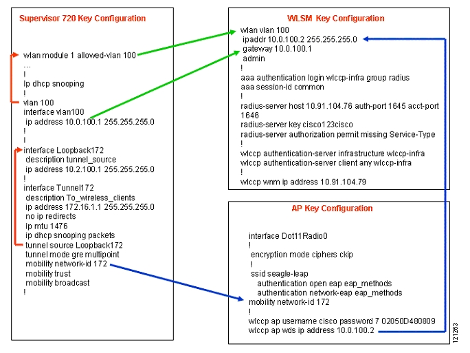
Figure 20 shows a configuration map of the configurations discussed in this document.
Figure 20 Configuration Map
CCSP, CCVP, the Cisco Square Bridge logo, Follow Me Browsing, and StackWise are trademarks of Cisco Systems, Inc.; Changing the Way We Work, Live, Play, and Learn, and iQuick Study are service marks of Cisco Systems, Inc.; and Access Registrar, Aironet, BPX, Catalyst, CCDA, CCDP, CCIE, CCIP, CCNA, CCNP, Cisco, the Cisco Certified Internetwork Expert logo, Cisco IOS, Cisco Press, Cisco Systems, Cisco Systems Capital, the Cisco Systems logo, Cisco Unity, Enterprise/Solver, EtherChannel, EtherFast, EtherSwitch, Fast Step, FormShare, GigaDrive, GigaStack, HomeLink, Internet Quotient, IOS, IP/TV, iQ Expertise, the iQ logo, iQ Net Readiness Scorecard, LightStream, Linksys, MeetingPlace, MGX, the Networkers logo, Networking Academy, Network Registrar, Packet, PIX, Post-Routing, Pre-Routing, ProConnect, RateMUX, ScriptShare, SlideCast, SMARTnet, The Fastest Way to Increase Your Internet Quotient, and TransPath are registered trademarks of Cisco Systems, Inc. and/or its affiliates in the United States and certain other countries.
All other trademarks mentioned in this document or Website are the property of their respective owners. The use of the word partner does not imply a partnership relationship between Cisco and any other company. (0601R)
![]()
![]()
![]()
![]()
![]()
![]()
![]()
![]()
Posted: Wed Mar 1 16:18:16 PST 2006
All contents are Copyright © 1992--2006 Cisco Systems, Inc. All rights reserved.
Important Notices and Privacy Statement.