|
|

Table Of Contents
Guidelines for Using LWAPP-Enabled Cisco Aironet Access Points
Performing a Pre-Installation Configuration
Deploying the Access Point on the Wireless Network
Reverting the Access Point Back to Autonomous Mode
Cisco One-Year Limited Hardware Warranty Terms
Preface
This guide will help you to install a Cisco Aironet Lightweight Access Point Protocol (LWAPP)-enabled access point on your wireless network. The following Cisco Aironet access points currently support LWAPP:
•
Cisco Aironet 1130AG
•
•
LWAPP-enabled access points are part of the Cisco Integrated Wireless Network Solution and require no manual configuration before they are mounted. The access point is configured by an LWAPP-capable Cisco wireless LAN controller.
Safety Information
The FCC with its action in ET Docket 96-8 has adopted a safety standard for human exposure to radio frequency (RF) electromagnetic energy emitted by FCC certified equipment. When used with approved Cisco Aironet antennas, Cisco Aironet products meet the uncontrolled environmental limits found in OET-65 and ANSI C95.1, 1991. Proper installation of this radio according to the instructions found in this manual will result in user exposure that is substantially below the FCC recommended limits.
•
•
Warnings
Translated versions of the following safety warnings are provided in Appendix A of the appropriate Cisco Aironet Access Point Hardware Installation Guide.
Warning
Warning
Warning
20A Statement 1005
Warning
Warning
Warning
Introduction
In the Cisco Centralized WLAN architecture, LWAPP-enabled access points operate in the lightweight mode (as opposed to the autonomous mode). The access points associate to a Cisco WLAN controller. The controller manages the configuration, firmware, and control transactions such as 802.1x authentication. In addition, all wireless traffic is tunneled through the controller.
LWAPP is an IETF draft protocol that defines the control messaging for setup and path authentication and run-time operations. LWAPP also defines the tunneling mechanism for data traffic.
In an LWAPP environment, a Cisco Aironet LWAPP-enabled access point discovers a controller by using LWAPP discovery mechanisms and then sends it an LWAPP join request. The controller sends the access point an LWAPP join response allowing the access point to join the controller. When the access point is joined, the controller downloads its software if the versions on the access point and controller do not match.
LWAPP secures the control communication between the access point and controller by means of a secure key distribution, utilizing X.509 certificates on both the access point and controller.
After an access point joins a controller, you can reassign it to any controller on your network.
It is possible to convert an LWAPP-enabled Cisco Aironet access point to autonomous mode. Refer to the product documentation for detailed instructions. See also the "Reverting the Access Point Back to Autonomous Mode" section to access the documentation on Cisco.com.
Guidelines for Using LWAPP-Enabled Cisco Aironet Access Points
You should keep these guidelines in mind when you use an LWAPP-enabled Cisco Aironet access point:
•
•
•
•
•
Using DHCP Option 43
You can use DHCP Option 43 to provide a list of WLAN controller IP addresses to the access points, enabling the access point to find and join a WLAN controller.
Cisco Aironet access points use the type-length-value (TLV) format for DHCP option 43. DHCP servers must be programmed to return the option based on the access point's DHCP Vendor Class Identifier (VCI) string (DHCP Option 60).
The following table lists the VCI strings for Cisco access points capable of operating in lightweight mode.
Cisco Aironet 1130 Series
Cisco AP c1130
Cisco Aironet 1200 Series
Cisco AP c1200
Cisco Aironet 1240 Series
Cisco AP c1240
This is the format of the TLV block:
•
•
•
Refer to the product documentation for your DHCP server for instructions on configuring DHCP Option 43. The Application Note: Upgrading Autonomous Cisco Aironet Access Points To Lightweight Mode contains example steps for configuring Option 43 on a DHCP server. See the "Reverting the Access Point Back to Autonomous Mode" section for instructions on how to access this document on Cisco.com.
Getting Started
This guide assumes that a site survey has been performed (or you have used the site planning tool), that access point locations have been selected, and that you intend to install an access point in each location.
You should have the following information about your wireless network available:
•
•
•
Note
If you do not have a map, Cisco recommends that you make one so you can record the MAC addresses from each location and return them to the person who is planning or managing your wireless network.
Unpacking the Access Point
Follow these steps to unpack the access point:
1.
2.
3.
Installation Summary
Installing the access point involves these operations:
•
•
•
Performing a Pre-Installation Configuration
The following procedures are designed to ensure that your access point installation and initial operation go as expected.
Note
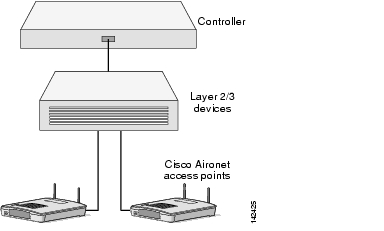
Configuration Setup
The figure below explains the configuration setup.
Follow these steps to perform the pre-installation configuration.
1.
a.
b.
c.
d.
2.
a.
Note
b.
Note
c.
Note
d.
e.
3.
4.
5.
6.
Note
Mounting the Access Point
Detailed mounting instructions are in the Cisco Aironet Hardware Configuration Guide for the access point you are mounting. These documents are available on Cisco.com.
Warning
Deploying the Access Point on the Wireless Network
After you have mounted the access point, follow these steps to deploy it on the wireless network.
1.
2.
f.
3.
a.
Note
Reverting the Access Point Back to Autonomous Mode
It is possible to revert an LWAPP-enabled Cisco Aironet access point back to autonomous mode. Please refer to Upgrading Autonomous Cisco Aironet Access Points to Lightweight Mode for detailed instructions on reverting to autonomous mode. Use this URL to browse to that document on Cisco.com or follow the steps below to navigate to the URL:
http://www.cisco.com/en/US/products/ps6366/prod_technical_reference_list.html
1.
2.
3.
4.
5.
6.
7.
In Case of Difficulty
If you followed the instructions in previous sections of this guide, you should have had no trouble getting your access point installed and running. If you do experience difficulty, before contacting Cisco, look for a solution to your problem in this guide or the troubleshooting chapter of the Cisco Aironet Point Hardware Installation Guide for the access point you are using. These, and other documents, are available on Cisco.com. Follow these steps to access and download these documents:
1.
2.
3.
4.
5.
6.
The Technical Support and Documentation page also contains valuable technical support resources.
Compliance Information
This equipment has been tested and found to comply with the European Telecommunications Standard ETS 300.328. This standard covers Wideband Data Transmission Systems referred to in CEPT recommendation T/R 10.01.
This type-accepted equipment is designed to provide reasonable protection against harmful interference when the equipment is operated in a commercial environment. This equipment generates, uses, and can radiate radio frequency energy and, if not installed in accordance with the instruction manual, may cause harmful interference to radio communications.
The Declarations of Compliance for this product relevant to the European Union and other countries following EU Directive 1999/5/EC (R&TTE Directive) can be found in the Cisco Aironet Access Point Hardware Installation Guide for the access point you are using. This guide is available on Cisco.com.
Cisco One-Year Limited Hardware Warranty Terms
There are special terms applicable to your hardware warranty and various services that you can use during the warranty period. Your formal Warranty Statement, including the warranties and license agreements applicable to Cisco software, is available on Cisco.com. Follow these steps to access and download the Cisco Information Packet and your warranty and license agreements from Cisco.com.
1.
http://www.cisco.com/univercd/cc/td/doc/es_inpck/cetrans.htm
The Warranties and License Agreements page appears.
2.
a.
b.
c.
The Cisco Limited Warranty and Software License page from the Information Packet appears.
d.
Note
3.
a.
78-10747-01C0
b.
c.
The Cisco warranty page appears.
d.
You can also contact the Cisco service and support website for assistance:
http://www.cisco.com/public/Support_root.shtml.
Duration of Hardware Warranty
One (1) Year
Replacement, Repair, or Refund Policy for Hardware
Cisco or its service center will use commercially reasonable efforts to ship a replacement part within ten (10) working days after receipt of a Return Materials Authorization (RMA) request. Actual delivery times can vary, depending on the customer location.
Cisco reserves the right to refund the purchase price as its exclusive warranty remedy.
To Receive a Return Materials Authorization (RMA) Number
Contact the company from whom you purchased the product. If you purchased the product directly from Cisco, contact your Cisco Sales and Service Representative.
Complete the information below, and keep it for reference.
Company product purchased from
Company telephone number
Product model number
Product serial number
Maintenance contract number
![]()
![]()
![]()
![]()
![]()
![]()
![]()
![]()
Posted: Tue Sep 6 08:25:13 PDT 2005
All contents are Copyright © 1992--2005 Cisco Systems, Inc. All rights reserved.
Important Notices and Privacy Statement.