|
|

Table Of Contents
Declaration of Conformity with Regard to the EU Directive
1999/5/EC (R&TTE Directive)Products with Integral Antennas
Products with External Antennas
Obtaining Documents from Cisco.com
EU Directive 1999/5/EC-Compliance
Information for the AIR-AP1131AG-E-K9-P, AIR-RM21A-E-K9-P, and AIR-RM22A-E-K9-P
September 15, 2004
This document contains compliance information for Cisco Aironet products AIR-AP1131AG-E-K9-P, AIR-RM21A-E-K9-P, and AIR-RM22A-E-K9-P that is relevant to the European Union and other countries that have implemented the EU Directive 1999/5/EC.
Contents
•
Scope
•
•
•
Scope
The information in this document is applicable to the Cisco Aironet 5-GHz single-band and 2.4- and 5-GHz dual-band wireless LAN products that currently include:
•
•
In addition, any AIR-AP12xx platform can be equipped with either an AIR-RM21A-E-K9-P or AIR-RM22A-E-K9-P 5-GHz radio module.
The equipment operates in the 5150- to 5350-MHz frequency range and, depending on the product configuration, also in the 2400- to 2483.5-MHz frequency range.
National regulations may require that operations be limited to portions of the frequency ranges identified above. See the "National Restrictions" section for complete details.
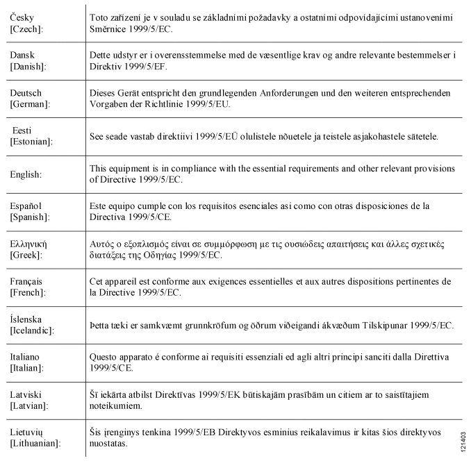
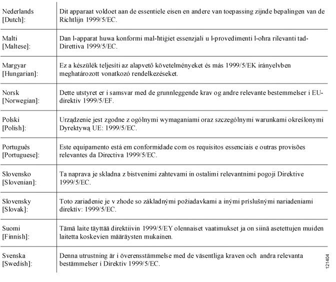
Declaration of Conformity with Regard to the EU Directive
1999/5/EC (R&TTE Directive)
Note
The following standards were applied during the assessment of the product against the requirements of the Directive 1999/5/EC:
•
•
•
Note
Note
CE Marking
For the Cisco Aironet AIR-AP1131AG-E-K9-P, AIR-RM21A-E-K9-P, or AIR-RM22A-E-K9-P, the following CE mark and class-2 identifier are affixed to the equipment and its packaging:
National Restrictions
The 2.400- to 2483.5-MHz band is available in all EU member states for indoor as well as outdoor usage. In the majority of the countries, the maximum power allowed is 100 mW eirp.
With regard to operation in the 5-GHz bands, these products meet the requirements as specified in the Guidance Document produced by the CEPT/ECC WG FM for `Interim Arrangements for 5-GHz Wireless LANs' (September 2002). The equipment can operate in either band (5150- to 5250-MHz or 5150- to 5350-Mhz) and is intended to be placed on the market only in those countries that have a permanent or interim regulation in place by which the equipment without DFS (radar detection) is allowed to operate in part of the 5-GHz frequency band and if applicable, at a reduced output power level.
For all countries, the operation in the 5-GHz bands (5150- to 5350-MHz) is restricted to indoor use only.
Table 1 contains an overview of the countries in which the product is intended to be placed on the market together with the applicable frequency band and the maximum allowed power (eirp).
Table 1 Country Specific Frequency Ranges and Power Levels
All EU countries
2400-2483.5
1001
DK, NO
5150-5250
50
AT, DE, IT, PT
5150-5250
60
FR, NL, SI, SK
5150-5250
200
BE, FI, IR, UK, LU, ES, CH , LI
5150-5350
120
GR, PL
5150-5350
200
1 See the next page for the specific situation for 2.4-GHz in France.
Cisco recommends that you check with the local authorities for the latest status of their national regulations for Wireless LANs or for regulations in countries not listed in Table 1.
The following sections identify EU countries having additional requirements or restrictions than those listed in Table 1.
Italy
Outdoor usage is only allowed when operating in the 2.4-GHz band.
This product meets the National Radio Interface and the requirements specified in the National Frequency Allocation Table for Italy. Unless operating within the boundaries of the owner's property, the use of these wireless LAN products requires a `general authorization'. Please check http://www.comunicazioni.it/it/ for more details.
France
Outdoor usage is only allowed when operating in the 2.4-GHz band. However, the output power is restricted in some parts of the band. Please see Table 2 or check http://www.art-telecom.fr/ for more details.
Belgium
Outdoor usage is only allowed when operating in the 2.4-GHz band. Outdoor wireless links with a range in excess of 300 meters need to be notified at the Belgian Institute of Postal services and Telecommunications (BIPT). Please check http://www.bipt.be/langue.htm for more details.
Note
Note
Antennas
Products with Integral Antennas
The 5-GHz wireless LAN products AIR-RM21A-E-K9-P and the dual band (2.4- and 5-GHz) wireless LAN product AIR-AP1131AG-E-K9-P have integral antennas which cannot be removed or which are not user accessible. Nevertheless, as the regulatory limits are not the same throughout the EU, users may need to adjust the conducted power setting for the radio to meet the eirp limits applicable in their country or region.
AIR-AP1131AG-E-K9-P
The AIR-AP1131AG-E-K9-P is a dual band (2.4- and 5-GHz) access point. The maximum conducted power settings for each band and for each of the applicable regulatory limits is given in Table 3. See the "National Restrictions" section to obtain the applicable regulatory limit in your country.
AIR-RM21A-E-K9-P
The AIR-RM21A-E-K9-P is a 5-GHz 802.11a radio module that incorporates an articulating antenna paddle that contains both omnidirectional and patch antennas. Whether the antenna performs as an omnidirectional antenna (such as ceiling or desktop mounting) or as a directional antenna (such as wall mounting) is defined by the installation. The maximum conducted power setting for both cases and for each of the applicable regulatory limits is listed in Table 4. See the "National Restrictions" section to obtain the applicable regulatory limit in your country.
Products with External Antennas
AIR-RM22A-E-K9-P
The AIR-RM21A-E-K9-P is a 5-GHz 802.11a product that can be equipped with external antennas.
Table 5 lists the antennas that were assessed together with the equipment against the requirements of the R&TTE directive. Depending on the country, a different regulatory limit might be applicable. It is therefore the responsibility of the end user to select a power level that, together with the antenna, results in an eirp level that is below the applicable limit.
The maximum conducted power setting for each of the antennas and the applicable regulatory limits is provided in Table 5. See the "National Restrictions" section to identify the regulatory limit in your country.
Operating Frequency
The operating frequency in a wireless LAN is determined by the access point. As such, it is important that the access point is correctly configured to meet the local regulations. See the "National Restrictions" section for country specific operating frequency ranges.
Changing Output Power
It is assumed that the AIR-RM21A-E-K9-P and AIR-RM22A-E-K9-P modules have been mounted in a Cisco Aironet 1200 Series Access Point. Connect your PC to the Ethernet port of the1200 or 1131AG series access point and follow these steps to change the output power to meet the local regulations.
Note
Step 1
Step 2
Step 3
Note
Step 4
Step 5
Step 6
Step 7
Table 6 lists the output power levels (conducted) for the 2.4-GHz and 5-GHz bands.
Table 6 Available Output Power Levels
(dBm)
(dBm)17
11
8
5
2
-117
15
14
11
8
5
2
-1
Step 8
Step 9
Note
Obtaining Documents from Cisco.com
Follow these steps to obtain any of the online documents mentioned in this document.
Step 1
Step 2
Step 3
Step 4
Step 5
Step 6
Note
Step 7
Note
Copyright © 2004 Cisco Systems, Inc. All rights reserved.
![]()
![]()
![]()
![]()
![]()
![]()
![]()
![]()
Posted: Thu Nov 18 15:14:04 PST 2004
All contents are Copyright © 1992--2004 Cisco Systems, Inc. All rights reserved.
Important Notices and Privacy Statement.