|
|

Table Of Contents
1100 Series Installation Instructions
Preparing the Access Point and Work Area
1200 Series Installation Instructions
Preparing the Access Point and Work Area
Removing the Blank Spacer Card
Installing the 802.11g Radio Card
Attaching the Compliance Labels
Cisco One-Year Limited Hardware Warranty Terms
Preface
This guide is designed to help you install an IEEE 802.11g-compliant radio in a Cisco Aironet 1100 or 1200 Series Access Point. Detailed installation and configuration information can be found in the following documents:
•
Cisco Aironet 1100 Series Access Point Hardware Installation Guide
•
•
Note
Documentation for the 1100 and 1200 series access points is available at Cisco.com. Follow these steps to access it.
1.
2.
3.
4.
a.
b.
5.
6.
Introduction
The Cisco Aironet IEEE 802.11g-compliant radio (hereafter called the 802.11g radio) is designed to upgrade 1100 and 1200 series access points to IEEE 802.11g standards. The radio delivers 100 milliwatts (mW) maximum transmit power at 1, 2, 5.5, and 11 megabits per second (Mbps) data rates and 30 mW maximum at all other data rates. The radio supports data rates of up to 54 Mbps.
This guide provides instructions for installing or replacing an 802.11g radio in an 1100 or 1200 series access point. The following operations summarize the upgrade procedure:
1.
2.
3.
4.
5.
6.
Caution
Unpacking the Radio
Each 802.11g radio is shipped with the following items:
•
•
•
•
If anything is missing or damaged, contact your Cisco representative for support.
1100 Series Installation Instructions
Note
Preparing the Access Point and Work Area
Follow these steps to prepare your access point and work area before installing the 802.11g radio:
1.
2.
3.
4.
5.
6.
Removing the Back Cover
Follow these steps to remove the access point's back cover:
1.
Caution
2.
3.
4.
Removing the 2.4-GHz Radio
Follow these steps to remove the 2.4-GHz radio card from your access point:
1.
Plus-shaped (+) support post
2.4-Ghz radio card
Antenna card
Card retaining clips
Support bracket
Mini-PCI connector
2.
3.
Note
4.
a.
b.
5.
Caution
6.
Caution
7.
Note
Installing the 802.11g Radio
Follow these steps to install the 802.11g radio:
Caution
1.
2.
3.
Caution
4.
5.
a.
b.
6.
7.
8.
9.
10.
a.
b.
c.
Caution
Replacing the Back Cover
Follow these steps to replace the back cover:
1.
2.
3.
4.
Configuring the 802.11g Radio
Refer to the following documents to configure the 802.11g radio:
•
•
These documents are available at Cisco.com. Follow the steps on page 4 to access them.
1200 Series Installation Instructions
Note
Caution
Preparing the Access Point and Work Area
Follow these steps to prepare your access point and work area:
1.
2.
3.
4.
5.
6.
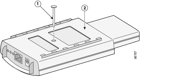
Opening the Access Cover
Follow these steps to open the 2.4-GHz radio access cover:
1.
2.
If your access point was not configured with a 2.4-GHz radio, go to the next section. If you are replacing an existing 2.4-GHz radio, go to the "Removing a 2.4-GHz Radio" section on page 25.
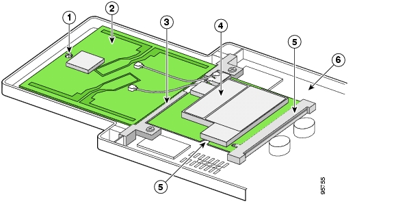
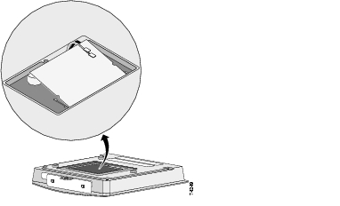
Removing the Blank Spacer Card
When your access point is not configured with a 2.4-GHz radio, it contains a blank spacer card in the internal mini-PCI connector. You must remove the blank spacer card prior to installing your 802.11g radio. If you are replacing an existing 2.4-GHz radio, go to the "Removing a 2.4-GHz Radio" section on page 25.
Caution
Follow these steps to remove the blank spacer card from the mini-PCI connector. It may be helpful to refer to the following illustration before you proceed.
Caution
1.
2.
3.
Caution
4.
5.
6.
Removing a 2.4-GHz Radio
Follow these steps to remove a 2.4-GHz radio card from your access point.
Caution
Caution
Caution
1.
2.
a.
b.
c.
3.
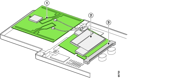
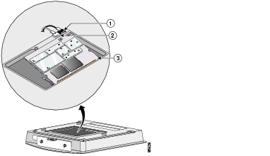
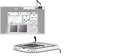
Installing the 802.11g Radio Card
Follow these steps to install the 802.11g radio card:
1.
2.
3.
4.
5.
a.
b.
6.
7.
a.
b.
c.
d.
Caution
8.
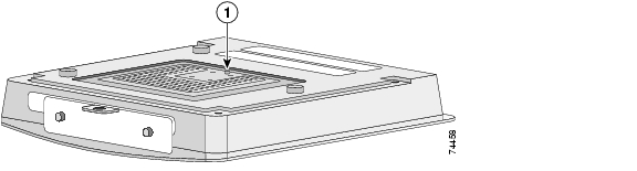
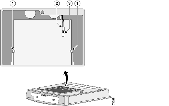
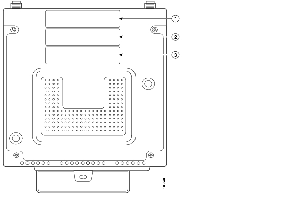
Attaching the Compliance Labels
There are three places on the 1200 series access point dedicated to compliance labels, one for the product compliance label and two for the radio compliance labels. The locations are shown in the following illustration.
The product compliance label always occupies the top space (location 1). The two spaces below (locations 2 and 3) contain the radio compliance labels. Whether or not locations 2 or 3 contain labels depends on how your access point is configured. For example, a dual-band access point could have two radio compliance labels (one for each radio device installed), or it could have only a product compliance label, depending on how it was ordered.
Make sure your that access point has the correct labels after you install or upgrade its radio configuration so that it will be in compliance with regulations in your country.
Placing the Labels
The 802.11g radio upgrade kit ships with the following labels for the 1100 and 1200 series access points:
•
•
•
The following table shows where to place the labels on your 1200 series access point, based on the model you are upgrading. Follow these steps to place the labels correctly:
1.
2.
3.
Configuring the 802.11g Radio
Refer to the following documents to configure the 802.11g radio:
•
•
These documents are available at Cisco.com. Follow the steps on page 1 to access them.
In Case of Difficulty
If you followed the instructions in previous sections of this guide, you should have had no trouble getting your access point installed and running. However, if you did experience difficulty, help is available from Cisco. Before contacting Cisco, look for a solution to your problem in the troubleshooting sections of the following documents:
•
•
•
The Technical Assistance Center's list of top wireless technology issues contains additional troubleshooting information. Follow these steps to access this list:
1.
2.
3.
4.
5.
6.
Safety Information
The FCC with its action in ET Docket 96-8 has adopted a safety standard for human exposure to radio frequency (RF) electromagnetic energy emitted by FCC certified equipment. When used with approved Cisco Aironet antennas, Cisco Aironet products meet the uncontrolled environmental limits found in OET-65 and ANSI C95.1, 1991. Proper installation of this radio according to the instructions found in the Cisco Aironet 1100 Series Access Point Hardware Installation Guide, and the Cisco Aironet 1200 Series Hardware Installation Guide will result in user exposure that is substantially below the FCC recommended limits.
•
•
•
•
High-gain, wall-mount, or mast-mount antennas are designed to be professionally installed. Cisco recommends that you contact your professional installer, VAR, or antenna manufacturer to obtain proper installation requirements.
Warning
Warning
(20 cm) from the body of all persons.
Compliance Information
This equipment has been tested and found to comply with the European Telecommunications Standard ETS 300.328. This standard covers Wideband Data Transmission Systems referred to in CEPT recommendation T/R 10.01.
This type-accepted equipment is designed to provide reasonable protection against harmful interference when the equipment is operated in a commercial environment. this equipment generates, uses, and can radiate radio frequency energy and, if not installed in accordance with the instruction manual, may cause harmful interference to radio communications.
Cisco One-Year Limited Hardware Warranty Terms
There are special terms applicable to your hardware warranty and various services that you can use during the warranty period. Your formal Warranty Statement, including the warranties and license agreements applicable to Cisco software, is available on Cisco.com. Follow these steps to access and download the Cisco Information Packet and your warranty and license agreements from Cisco.com.
1.
http://www.cisco.com/univercd/cc/td/doc/es_inpck/cetrans.htm
The Warranties and License Agreements page appears.
2.
a.
b.
c.
The Cisco Limited Warranty and Software License page from the Information Packet appears.
d.
Note
3.
a.
78-10747-01C0
b.
c.
The Cisco warranty page appears.
d.
You can also contact the Cisco service and support website for assistance:
http://www.cisco.com/public/Support_root.shtml.
Duration of Hardware Warranty
One (1) Year
Replacement, Repair, or Refund Policy for Hardware
Cisco or its service center will use commercially reasonable efforts to ship a replacement part within ten (10) working days after receipt of a Return Materials Authorization (RMA) request. Actual delivery times can vary, depending on the customer location.
Cisco reserves the right to refund the purchase price as its exclusive warranty remedy.
To Receive a Return Materials Authorization (RMA) Number
Contact the company from whom you purchased the product. If you purchased the product directly from Cisco, contact your Cisco Sales and Service Representative.
Complete the information below, and keep it for reference.
Company product purchased from
Company telephone number
Product model number
Product serial number
Maintenance contract number
![]()
![]()
![]()
![]()
![]()
![]()
![]()
![]()
Posted: Thu Jul 29 12:55:20 PDT 2004
All contents are Copyright © 1992--2004 Cisco Systems, Inc. All rights reserved.
Important Notices and Privacy Statement.