|
|

Table Of Contents
Installation and Configuration
Collecting Required Tools and Supplies
Pre-Installation Configuration
Preparing a Version 3.0 Cisco Aironet 1000 Series Lightweight Access Point
Alternate Method of Preparing a Version 3.0 Cisco Aironet 1000 Series Lightweight Access Point
Mounting the Cisco Aironet 1000 Series Lightweight Access Points
Installation and Configuration
This guide provides you with the information needed to mount AP1020 and AP1030 Cisco Aironet 1000 Series 802.11a/b/g lightweight access points. Cisco Aironet 1000 Series 802.11a/b/g lightweight access points are part of the innovative Cisco Wireless LAN Solution (Cisco WLAN Solution), and require no manual configuration after they are mounted.
This document is written assuming that you have already performed a site survey as described in the Cisco Aironet 1000 Series IEEE 802.11a/b/g Lightweight Access Point Deployment Guide, that Cisco Aironet 1000 Series lightweight access point locations and mounting options have been selected, and that you have one Cisco Aironet 1000 Series lightweight access point per indicated location.
After the site survey is done, you should have a map indicating the following:
•
Cisco Aironet 1000 Series lightweight access point locations.
•
•
Caution
If you do not have a map, make one so you can record the MAC addresses from each location and return them to the person who is planning or managing this wireless network.
Refer to the following sections to install the Cisco Aironet 1000 Series 802.11a/b/g lightweight access points.
Note
For more details about Cisco Aironet 1000 Series lightweight access point installations, refer to the " Planning Notes" section at the end of this document.
ATTENTION!
While Cisco Aironet 1000 Series IEEE 802.11a/b/g lightweight access points have been engineered for easy installation, there are some very important guidelines for installation:
•
•
•
•
•
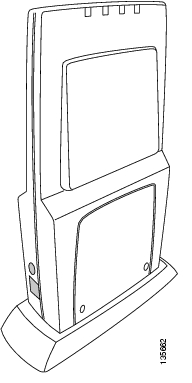
Figure 1 Access Point Installed Vertically
•
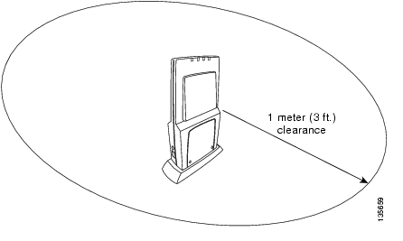
Figure 2 Access Point Clearance
•
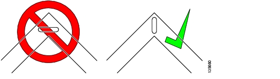
Figure 3 Mounting the Access Point in the Correct Direction
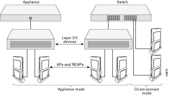
When a Cisco Aironet 1000 Series lightweight access point is configured with an IP address and is moved to a different IP segment, it attempts to join a Cisco Wireless LAN Controller. If it is unable to join a Cisco Wireless LAN Controller after a number of attempts, it does an arp for the default configured gateway. If the Cisco Aironet 1000 Series lightweight access point is on the wrong subnet, it will not be able to resolve the gateway arp and it will attempt to contact a DHCP server. This is the Cisco Aironet 1000 Series lightweight access point IP address fallback feature. However, if the destination IP segment does not have a DHCP server, the Cisco Aironet 1000 Series lightweight access point retains its original IP address and can never join the network.
Collecting Required Tools and Supplies
This section describes the tools and information that you should have before installing the access point.
•
•
•
•
•
•
•
•
•
Continue with " Pre-Installation Configuration.
Pre-Installation Configuration
The following procedures are designed to ensure that your Cisco Aironet 1000 Series lightweight access point physical installation and that initial operation goes as expected. If you are unable to prepare your Cisco Aironet 1000 Series lightweight access point for deployment, this step also describes RMA (Return Material Authorization) procedures.
Perform the following procedure on each Cisco Aironet 1000 Series lightweight access point BEFORE deploying it in its final location.
•
•
If you are unable to perform the following procedure, refer to the " Obtaining Technical Assistance" section.
Preparing a Version 3.0 Cisco Aironet 1000 Series Lightweight Access Point
If your Cisco Aironet 1000 Series lightweight access point has Operating System 3.0 or a later version loaded on it, continue with this procedure.
Note
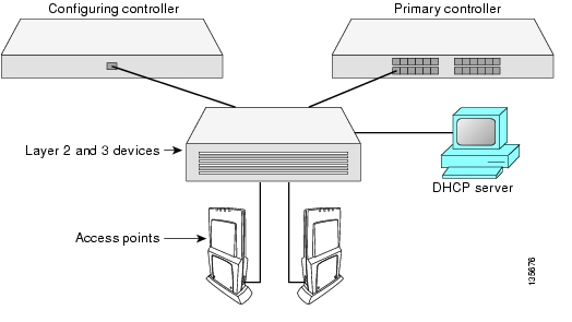
Configuration Setup
Figure 4 Configuration Setup
Does My Cisco Aironet 1000 Series Lightweight Access Point Qualify for this Procedure?
Does My Cisco Aironet 1000 Series Lightweight Access Point Qualify for this Procedure?If your 3.0 or later version Cisco Aironet 1000 Series lightweight access point(s) cannot be configured for any reason using the following procedure, refer to the " Obtaining Technical Assistance" section.
Configuration Steps for a Cisco Aironet 1000 Series Lightweight Access Point
To configure an access point, perform these steps:
Step 1
Note
a.
b.
Step 2
Step 3
a.
Note
b.
c.
d.
e.
Step 4
Note
•
•
•
•
Step 5
Note
Step 6
•
•
•
Step 7
After you have prepared all Cisco Aironet 1000 Series 802.11a/b/g lightweight access points, reconfigure the Cisco Wireless LAN Controller so it is not the Master. A Master Cisco Wireless LAN Controller should only be used for configuring Cisco Aironet 1000 Series 802.11a/b/g lightweight access points and not in a working network. Note that the Master Cisco Wireless LAN Controller is normally not used in a deployed network, so the Master Cisco Wireless LAN Controller setting is automatically disabled upon reboot or OS code upgrade.
After completing " Pre-Installation Configuration" for all Cisco Aironet 1000 Series 802.11a/b/g lightweight access points, continue with " Preparing Mounting Locations."
Alternate Method of Preparing a Version 3.0 Cisco Aironet 1000 Series Lightweight Access Point
If your Cisco Aironet 1000 Series lightweight access point has Operating System 3.0 or later, you may choose to use this procedure.
Note
Configuration Setup
Figure 5 Configuration Setup
Does My Cisco Aironet 1000 Series Lightweight Access Point Qualify for this Procedure?
Does My Cisco Aironet 1000 Series Lightweight Access Point Qualify for this Procedure?•
Configuration Steps for a Cisco 1000 Series Lightweight Access Point
1.
option controller code 43 = text;
option controller "<Switch IP Address>";
in which <Switch IP Address> is the IP address of the Cisco Wireless LAN Controller you are going to use to prepare the Cisco Aironet 1000 Series lightweight access point, or which can be a comma-delimited string of Cisco Wireless LAN Controller IP addresses.
(These commands direct all discovery messages for unconfigured Cisco Aironet 1000 Series 802.11a/b/g lightweight access points to the configuring Cisco Wireless LAN Controller.)
2.
3.
Note
4.
5.
a.
Note
b.
c.
6.
After the Cisco Aironet 1000 Series lightweight access point finds the configuring Cisco Wireless LAN Controller, it attempts to download the new Operating System code if the Cisco Aironet 1000 Series lightweight access point code version differs from the configuring Cisco Wireless LAN Controller code version. While this is happening, the LEDs on the top of the Cisco Aironet 1000 Series lightweight access point blink simultaneously.
7.
–
–
–
8.
document. If your Cisco Aironet 1000 Series lightweight access point fails this visual test, refer to the " Obtaining Technical Assistance" section to return your Cisco Aironet 1000 Series 802.11a/b/g lightweight access points.
Note
9.
–
–
–
After completing " Pre-Installation Configuration" for all Cisco Aironet 1000 Series 802.11a/b/g lightweight access points, continue with " Preparing Mounting Locations."
Preparing Mounting Locations
On your map, you should have the Cisco Aironet 1000 Series lightweight access point locations, mounting options, and power options.
Note
1.
–
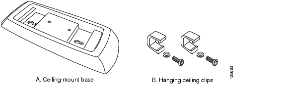
Figure 6 Factory-Supplied Mounting Options
–
–
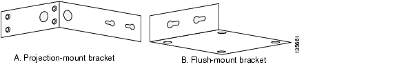
Figure 7 Factory-Orderable Mounting Brackets
2.
3.
4.
–
–
You are now ready to install the Cisco Aironet 1000 Series 802.11a/b/g lightweight access points. Continue with " Mounting the Cisco Aironet 1000 Series Lightweight Access Points."
Mounting the Cisco Aironet 1000 Series Lightweight Access Points
Using the supplied or optional orderable Cisco Aironet 1000 Series lightweight access point mounting kits, mount each Cisco Aironet 1000 Series lightweight access point in its indicated location, oriented as shown on the map. Note that you can mount the Cisco Aironet 1000 Series 802.11a/b/g lightweight access points in the ceiling plenum or below the ceiling, but that they perform best when mounted below the ceiling.
Note
The Cisco Aironet 1000 Series 802.11a/b/g lightweight access points can be mounted in one of the following configurations:
•
•
•
•
•
Ceiling Mount Base
When you are mounting the Cisco Aironet 1000 Series lightweight access point in the middle of a ceiling (flat sides toward the room or hallway), use the ceiling-mount base to mount the Cisco Aironet 1000 Series lightweight access point as shown in the following figure and as described below:
Figure 8 Attaching the Cisco Aironet 1000 Series Lightweight Access Point and Ceiling-Mount Base
1.
2.
3.
Note
4.
Note
5.
You installed the access point. Repeat " Mounting the Cisco Aironet 1000 Series Lightweight Access Points" for each location, and then continue with " Returning MAC Information."
Ceiling-Mount Clips
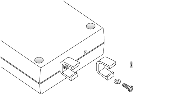
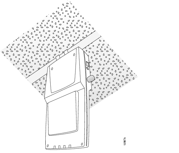
When you are mounting the Cisco Aironet 1000 Series lightweight access point on the extruded aluminium rails of a hanging ceiling, use the ceiling-mount clips to mount the Cisco Aironet 1000 Series lightweight access point as shown in the following figure and as described below:
Figure 9 Assembling the Cisco Aironet 1000 Series Lightweight Access Point and Ceiling-Mount Clips
1.
2.
3.
Figure 10 Clipping the Cisco Aironet 1000 Series Lightweight Access Point and Ceiling-Mount Clips to a Hanging-Ceiling Rail
4.
Note
•
You have installed the Cisco Aironet 1000 Series lightweight access point. Repeat " Mounting the Cisco Aironet 1000 Series Lightweight Access Points" for each Cisco Aironet 1000 Series lightweight access point location, and then continue with " Returning MAC Information."
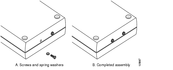
Projection Wall Mount
When you are mounting the Cisco Aironet 1000 Series lightweight access point out from a wall (flat sides along the wall or hallway), use an optional separately orderable factory-orderable projection-mount L-bracket.
1.
Note
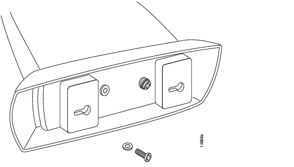
Figure 11 Attaching the Mounting Screws and Spring Washers to the Cisco Aironet 1000 Series Lightweight Access Point
2.
3.
4.
Note
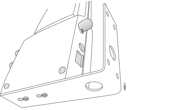
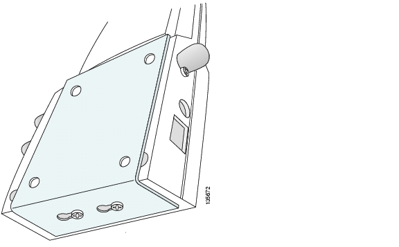
Figure 12 Attaching the Cisco Aironet 1000 Series Lightweight Access Point to the Projection-Mount Bracket
5.
Note
•
You have installed the Cisco Aironet 1000 Series lightweight access point. Repeat " Mounting the Cisco Aironet 1000 Series Lightweight Access Points" for each Cisco Aironet 1000 Series lightweight access point location, and then continue with " Returning MAC Information."
Flush Wall Mount
Flush Wall MountWhen you are mounting the Cisco Aironet 1000 Series lightweight access point against a wall (flat side toward the inside of the building), use an optional separately orderable factory-orderable flush-mount bracket.
1.
Note
Figure 13 Attaching the Mounting Screws and Spring Washers to the Cisco Aironet 1000 Series Lightweight Access Point
2.
3.
4.
Note
•
Figure 14 Attaching the Cisco Aironet 1000 Series Lightweight Access Point to the Flush-Mount Bracket
5.
Note
•
You have installed the Cisco Aironet 1000 Series lightweight access point. Repeat " Mounting the Cisco Aironet 1000 Series Lightweight Access Points" for each Cisco Aironet 1000 Series lightweight access point location, and then continue with " Returning MAC Information."
Returning MAC Information
When you have completed the installations as outlined in " Mounting the Cisco Aironet 1000 Series Lightweight Access Points," return the MAC addresses and their locations on the maps or floor plans to the network planner or manager. The Network operators will use the MAC address and location information to create maps for precise wireless Operating System management.
Also return any unused mounting kit hardware and external power supplies to the network planner or manager for use in future deployments.
Note
![]()
![]()
![]()
![]()
![]()
![]()
![]()
![]()
Posted: Wed Aug 31 23:33:37 PDT 2005
All contents are Copyright © 1992--2005 Cisco Systems, Inc. All rights reserved.
Important Notices and Privacy Statement.