|
|

Table Of Contents
Cisco Aironet 12 dBi High Gain Omnidirectional Antenna (AIR-ANT24120)
Obtaining Technical Assistance
Cisco Aironet 12 dBi High Gain Omnidirectional Antenna (AIR-ANT24120)
Overview
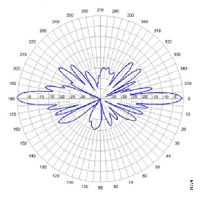
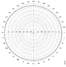
This document outlines the specifications and description of the 12-dBi high gain omnidirectional antenna. This antenna operates in the 2400-2500 MHz band and is designed for use outdoors. The antenna is compatible with Cisco Aironet radio products utilizing a reverse-polarity threaded naval connector (RP-TNC) connector.
The following information is provided in this document:
•
Overview
Technical Specifications
System Requirements
This antenna is designed for use with Cisco Aironet access points and bridges but can be used with any 2.4-GHz Cisco Aironet radio device that uses a reverse-polarity threaded naval connector (RP-TNC).
Installation Notes
Choosing a Mounting Location
The antenna is designed to create an omni-directional broadcast pattern. To achieve this pattern, the antenna should be mounted clear of any obstructions to the sides of the radiating element. If the mounting location is on the side of a building or tower, the antenna pattern will be blocked on the building or tower side.
Tools and Equipment Required
To install the antenna, you will need the following tools and equipment.
•
•
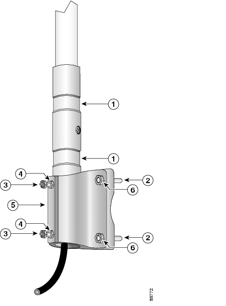
The following sections contain procedures for installing the antenna. Choose the procedure that applies to your situation. Use Figure 1 as a guide.
Mounting the Antenna
The antenna is provided with a mounting kit. This kit allows you to mount the antenna to masts up to three inches in diameter. The antenna is vertically polarized. Since the antenna has vertical gain, it is very important to mount the antenna in a vertical (not leaning) position for optimal performance.
Follow these steps to mount the antenna to a mast.
Step 1
Step 2
Step 3
Step 4
Step 5
Step 6
Step 7
Note
Figure 1 Antenna Mount Assembly
Antenna grooves
Jam nuts
5/16 x 18 U-bolt
Sandcast bracket
1/4-20 hex bolts
5/16-18 hex nut
Suggested Cable
Cisco recommends a high-quality, low-loss 50-ohm cable for use with the antenna, such as those listed in
Table 1.
Note
The antenna terminates with a special connector (reverse-TNC plug) after a short, 1-ft. cable. The mating connector to the antenna is an appropriate reverse-TNC jack connector. The connector on the opposite end varies according to the type of equipment used.
After the cable is attached to the antenna, make sure that the connections are sealed (if using outdoors) to prevent moisture and other weathering elements from affecting performance.
Note
Cisco recommends using a coax seal for outdoor connections. Silicon sealant or electrical tape are not recommended for sealing outdoor connections.
The final step is to attach the antenna to your wireless device.
Safety Precautions
Warning
Each year hundreds of people are killed or injured when attempting to install an antenna. In many of these cases, the victim was aware of the danger of electrocution, but did not take adequate steps to avoid the hazard.
For your safety, and to help you achieve a good installation, please read and follow these safety precautions. They may save your life!
1.
2.
3.
4.
5.
a.
b.
c.
6.
7.
If an accident should occur with the power lines call for qualified emergency help immediately.
Obtaining Technical Assistance
Cisco provides Cisco.com as a starting point for all technical assistance. Customers and partners can obtain online documentation, troubleshooting tips, and sample configurations from online tools by using the Cisco Technical Assistance Center (TAC) Web Site. Cisco.com registered users have complete access to the technical support resources on the Cisco TAC Web Site.
Cisco.com
Cisco.com is the foundation of a suite of interactive, networked services that provides immediate, open access to Cisco information, networking solutions, services, programs, and resources at any time, from anywhere in the world.
Cisco.com is a highly integrated Internet application and a powerful, easy-to-use tool that provides a broad range of features and services to help you with these tasks:
•
•
•
•
•
If you want to obtain customized information and service, you can self-register on Cisco.com. To access Cisco.com, go to this URL:
Technical Assistance Center
The Cisco Technical Assistance Center (TAC) is available to all customers who need technical assistance with a Cisco product, technology, or solution. Two levels of support are available: the Cisco TAC Web Site and the Cisco TAC Escalation Center.
Cisco TAC inquiries are categorized according to the urgency of the issue:
•
•
•
•
The Cisco TAC resource that you choose is based on the priority of the problem and the conditions of service contracts, when applicable.
Cisco TAC Web Site
You can use the Cisco TAC Web Site to resolve P3 and P4 issues yourself, saving both cost and time. The site provides around-the-clock access to online tools, knowledge bases, and software. To access the Cisco TAC Web Site, go to this URL:
All customers, partners, and resellers who have a valid Cisco service contract have complete access to the technical support resources on the Cisco TAC Web Site. The Cisco TAC Web Site requires a Cisco.com login ID and password. If you have a valid service contract but do not have a login ID or password, go to this URL to register:
http://www.cisco.com/register/
If you are a Cisco.com registered user, and you cannot resolve your technical issues by using the Cisco TAC Web Site, you can open a case online by using the TAC Case Open tool at this URL:
http://www.cisco.com/tac/caseopen
If you have Internet access, we recommend that you open P3 and P4 cases through the Cisco TAC Web Site.
Cisco TAC Escalation Center
The Cisco TAC Escalation Center addresses priority level 1 or priority level 2 issues. These classifications are assigned when severe network degradation significantly impacts business operations. When you contact the TAC Escalation Center with a P1 or P2 problem, a Cisco TAC engineer automatically opens a case.
To obtain a directory of toll-free Cisco TAC telephone numbers for your country, go to this URL:
http://www.cisco.com/warp/public/687/Directory/DirTAC.shtml
Before calling, please check with your network operations center to determine the level of Cisco support services to which your company is entitled: for example, SMARTnet, SMARTnet Onsite, or Network Supported Accounts (NSA). When you call the center, please have available your service agreement number and your product serial number.
Copyright © 2002-2003, Cisco Systems, Inc.
All rights reserved.
![]()
![]()
![]()
![]()
![]()
![]()
![]()
![]()
Posted: Fri Aug 12 05:36:34 PDT 2005
All contents are Copyright © 1992--2005 Cisco Systems, Inc. All rights reserved.
Important Notices and Privacy Statement.