|
|

This chapter describes how to use the Graphical User Interface (GUI) to configure the Cisco Secure Content Accelerator. The GUI provides a convenient, Web browser-based method of configuring the Secure Content Accelerator.
 |
Note The GUI cannot be used to configure the Secure Content Accelerator in FIPS Mode. See Chapter 6, Graphic al User Interface Reference, for further information. |
This chapter contains the following sections:
While most configuration options are available with the GUI, you must be aware of the following constraints:
The GUI has the following requirements:
...
Web Management:  disabled
...
Enter Privileged and Configuration modes and enable Web management using these commands:
enable
configure
web-mgmt enable
The default TCP service port is 80. If you change it with the web-mgmt port command, you must use that port to connect with the device via the Web browser. Enter show device to check the state. The status should be listed similar to the following:
...
Web Management:  enabled on port 80
...
We recommend that you restrict Web management access to the Secure Content Accelerator. Create one or more access lists using either the CLI (see "Example: Restricting Access using an Access List" in Chapter 4) or the GUI (as described later in this chapter.)
Follow these steps to use the GUI to manage the Secure Content Accelerator.
1. Launch the Web browser.
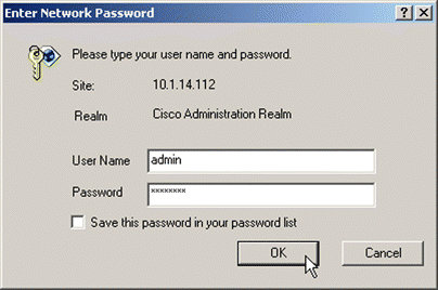
2. When configuring a device in dual-port mode from a computer via the "Server" port, enter the SSL appliance IP address in the Address text box and press Return or Enter. If an enable password has been defined on the device, you are prompted for an user name and the enable password, as shown in Figure 5-1. Use "admin" for the user name. If no enable password has been configured, the GUI starts at the General content area.
 |
Note Before configuring a device in two-port mode from the client side (via the "Network" port), you must first set up a secure server for this purpose. See "Config uring for Client-Side Access". |
myDevice> attach
myDevice> enable
myDevice# configure
(config[myDevice])> ssl
(config-ssl[myDevice])> server web create
(config-ssl-server[web])> ip address 127.0.0.1
(config-ssl-server[web])> sslport 443
(config-ssl-server[web])> remoteport 80
(config-ssl-server[web])> no transparent
(config-ssl-server[web])> cert default-1024
(config-ssl-server[web])> key default-1024
(config-ssl-server[web])> secpolicy all
(config-ssl-server[web])> finished
myDevice#
Type https:// and the IP address of the device in the Address text box of the browser, and press Enter. You receive a security alert dialog. Click Yes to proceed. If prompted, indicate that you wish to accept the certificate for this session only. You can proceed with configurations. You can also use the Subsystem tab in the Access content area to configure port access. Click the HTTPS Service Enable check box.
The GUI is divided into two main parts: the area panel on the left and content tabs on the right. Figure 5-2 shows an example of this interface. Take a few moments to familiarize yourself with the screen layout.
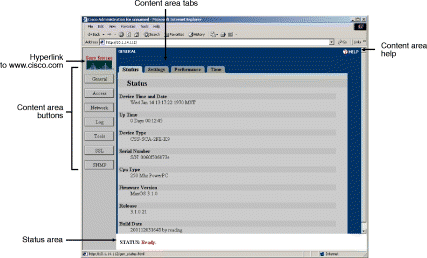
On the left is a panel with links to the seven main content areas.
The following examples demonstrate how to use the GUI to configure general Secure Content Accelerator settings.
 |
Note To save time, make all the changes you wish, then click Save to Flash to write the configuration to the device flash memory. |
Follow these steps to change the hostname of the device to myDevice.
1. Click General to activate the General content tabs.
2. Click the Settings tab. The Settings page opens, as shown in Figure 5-3
3. Type "myDevice" in the Device Name text box.
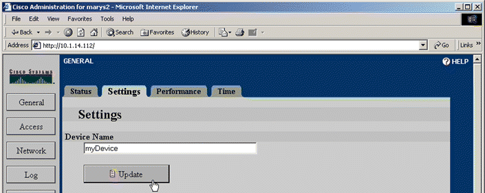
4. Click Update.
1. Click Network to activate the Network tabs.
2. Type the new IP address information including the appropriate netmask and default router in the Internet Address, Netmask, and Gateway text boxes, respectively, on the Settings tab. The Settings page opens, as shown in Figure 5-4.
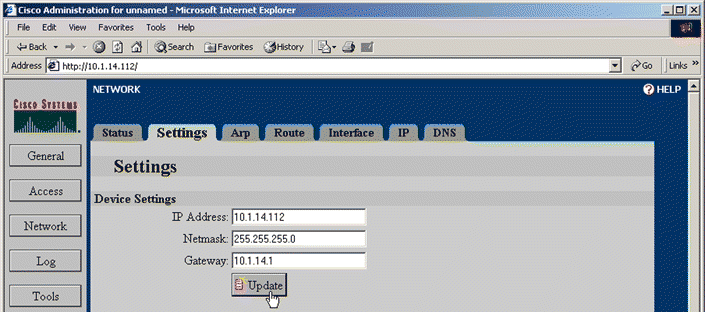
3. Click Update. The Status area tells you that the connection switches to the new address in 20 seconds.
 |
Note In certain situations, such as when changing to a different subnet, redirection might not occur. If the connection is not redirected, manually connect to the device. If you still are unable to connect, use the serial configuration manager to check the device configuration and try again. |
1. Click Network to activate the Network tabs.
2. Use the list box in the Network Interface or Server Interface panel of the Settings tab to change the Ethernet interface settings. The Settings page is shown in Figure 5-5.
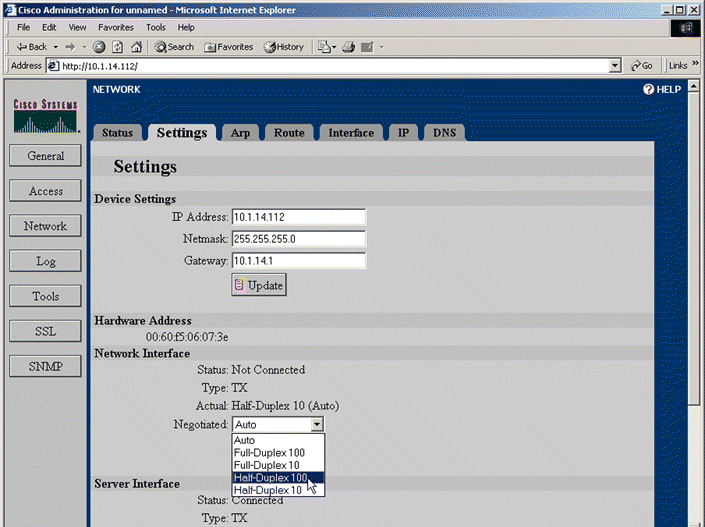
3. Click Update.
1. Click Network to activate the Network tabs.
2. Click the Settings tab. The Settings page opens, as shown in Figure 5-6.
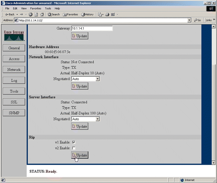
3. Scroll to the bottom of the page, if necessary, to see the Rip panel.
4. Select the Enabled check box.
5. Click Update.
1. Click Network to activate the Network tabs.
2. Click the Route tab. The Route page opens, as shown in Figure 5-7.
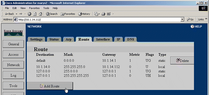
3. Scroll to the bottom of the page, if necessary, to see the Add Route button.
4. Click Add Route. The Add Route window opens as shown in Figure 5-8.
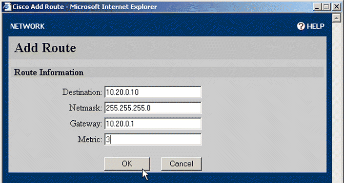
5. Type the addressing and gateway information in the appropriate text boxes. Type the number of hops into the Metric text box.
6. Click OK to add the route or Cancel to close the window without adding the route information.
1. Click Log to activate the Log tabs. The Settings page open automatically, as shown in Figure 5-9.
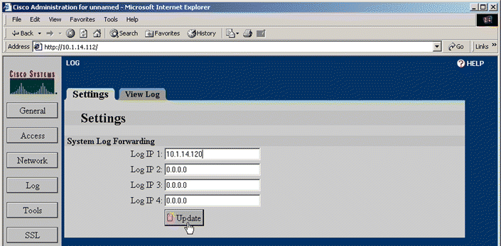
2. Enter the IP addresses of the syslog hosts in the System Log Forwarding text boxes on the Settings tab.
3. Click Update.
Use the View Log tab to display the syslog and clear the syslogs.
1. Click Access to activate the Access tabs.
2. Click the Access Control Lists tab. The Access Control Lists page opens, as shown in Figure 5-10.
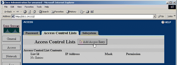
3. Click Add Access Entry. The Add Access Control List window opens, as shown in Figure 5-11.
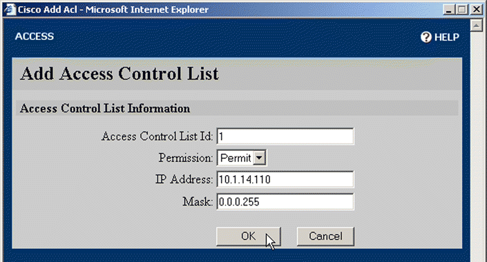
4. Enter the appropriate information for the list entry. (See the access-list command in Appendix C for more information.)
5. Click OK to create the access list entry and close the window.
6. Click the Subsystem tab. The Subsystem page opens, as shown in Figure 5-12.
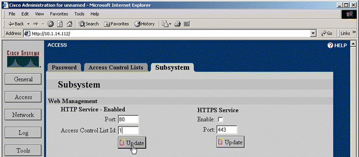
7. Type the number of the access list just created in the Access Control List Id text box of the Web Management panel. (You can also change the TCP port on this tab.)
8. Click Update.
1. Click Tools to activate the Tools tabs. The Restart page opens automatically, as shown in Figure 5-13.
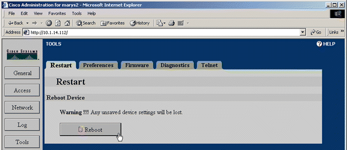
2. If you have made changes to the device configuration but have not saved them to flash memory, click Save to Flash in the Status area, as shown in Figure 5-14.
 |
Caution The appliance restarts using the configuration stored in flash memory. Any changes you have made but have not saved are lost. |

3. Click Reboot on the Restart page. The appliance reboots using the configuration stored in flash memory.
The Enable password is requested prior to connecting to the device.
1. Click Access to activate the Access tabs. The Password page opens automatically, as shown in Figure 5-15.
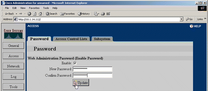
2. If an Enable password has already been assigned, type it in the Old Password text box.
3. Type the password to use in the New Password text box, and retype it in the Confirm New Password text box.
4. Click Update to set the password.
 |
Note To remove an existing Enable password entirely, clear the Enable checkbox, type the existing password in the Old Password text box. Click Update. |
1. Click SNMP to activate the SNMP tabs. The Settings page opens automatically, as shown in Figure 5-16.
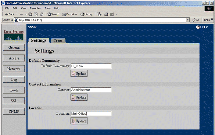
2. Type the default community, contact information, and location information in appropriate text boxes. Click Update after changing the value in each field and selecting the Enabled check box.
3. Click the Traps tab. The Traps page opens, as shown in Figure 5-17.
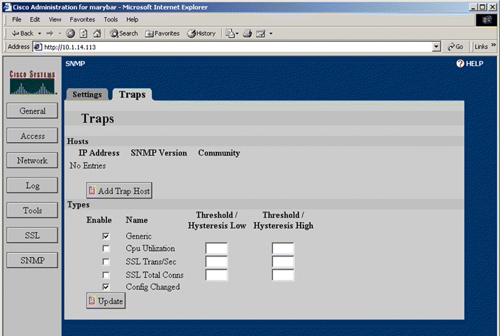
4. Click Add Trap Host to specify a host to which to send trapping messages. The Add Trap Host window opens, as shown in Figure 5-18.
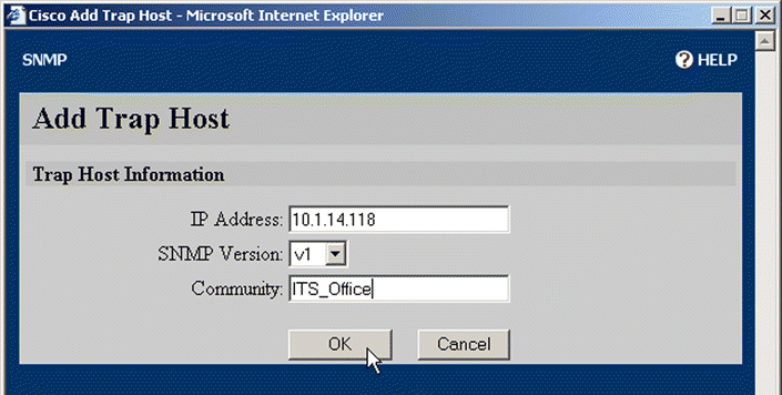
5. Type the host IP address into the IP Address text box. If you wish the trap messages to be sent to a community other than the default community, enter the community name in the Community text box. Select the desired version of SNMP from the SNMP Version list box.
6. Click OK to add the trap host.
7. Set the desired traps by selecting the Enable option buttons and typing appropriate values in the Threshold/Hysteresis Low and Hysteresis High text boxes. If you wish to use only one trap point, enter a value only in the Threshold/Hysteresis Low text box.
 |
Note Additional information is presented in the online Help for this tab. Click Help in the top right corner of the window. |
8. Click Update to set the configuration.
The following examples demonstrate how to set up SSL configurations for the Secure Content Accelerator. If necessary, refer to Chapter 3 to see how the Secure Content Accelerator works with SSL protocol information.
The first step is to load a key to assign to the secure server. In this example, a key is imported into the GUI.
1. Click SSL to activate the SSL tabs.
2. Click the Private Keys tab. The Private Keys page opens, as shown in Figure 5-19.
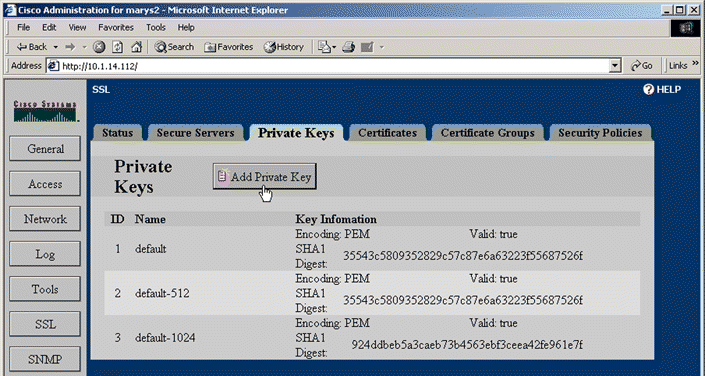
3. Click Add Private Key. The Add Private Key window opens, as shown in Figure 5-20.
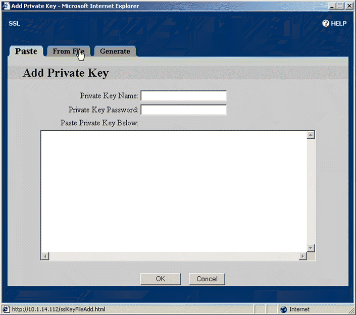
4. Click From File. The From File page opens, a shown in Figure 5-21. (In this example, the key is imported from a file. Alternatively, you can copy the key from the key file, and paste it into the Paste Private Key Here text box on the Paste tab. For an example of key generation, see " Example: Generating an RSA Private Key".)
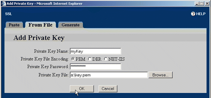
5. Type the key name, myKey, in the Private Key Name text box. Select the appropriate Private Key File Encoding option button. Type the password for the key in the Private Key Password text box. Enter the key file name and path or click the Browse button to find and select the file.
6. Click OK to load the key into the Secure Content Accelerator.
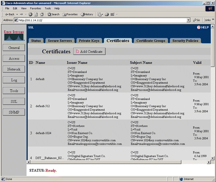
8. Click Add Certificate. The Add Certificate window opens, as shown in Figure 5-23.
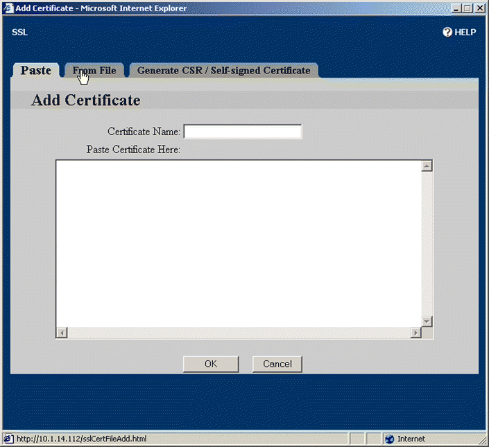
9. Click From File. The From File page opens, as shown in Figure 5-24. (In this example, the certificate is imported from a file. Alternatively, you can copy the certificate from the file, and paste it into the Paste Certificate Here text box on the Paste tab. For an example demonstrating certificate generation, see " Example: Generating a Self-Signed Certificate" below.)
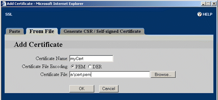
10. Type the certificate name, myCert, in the Certificate Name text box. Select the appropriate Certificate File Encoding option button. Enter the certificate fie name and path or click the Browse button to find and select the file.
11. Click OK to load the certificate into the Secure Content Accelerator.
12. Click the Security Policies tab. The Security Policies page opens, as shown in Figure 5-25.
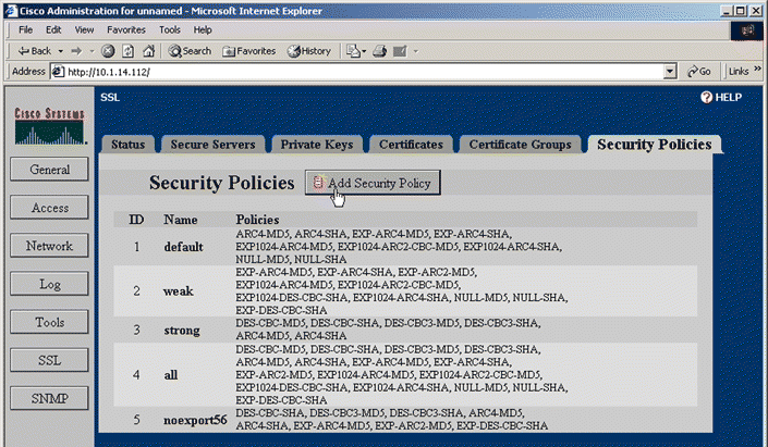
13. Click Add Security Policy. The Add Security Policy window opens, as shown in Figure 5-26.
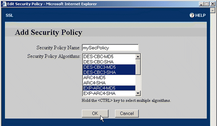
14. Type the desired name in the Security Policy Name text box. Select the policies to include in the new security policy by clicking and CTRL+clicking the entries in the Security Policy Algorithms list box.
15. Click OK to create the policy.
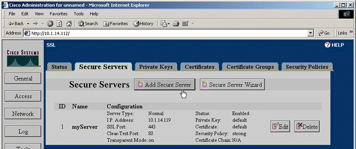
17. Click Add Secure Server. The Add Secure Server window opens, as shown in Figure 5-28.
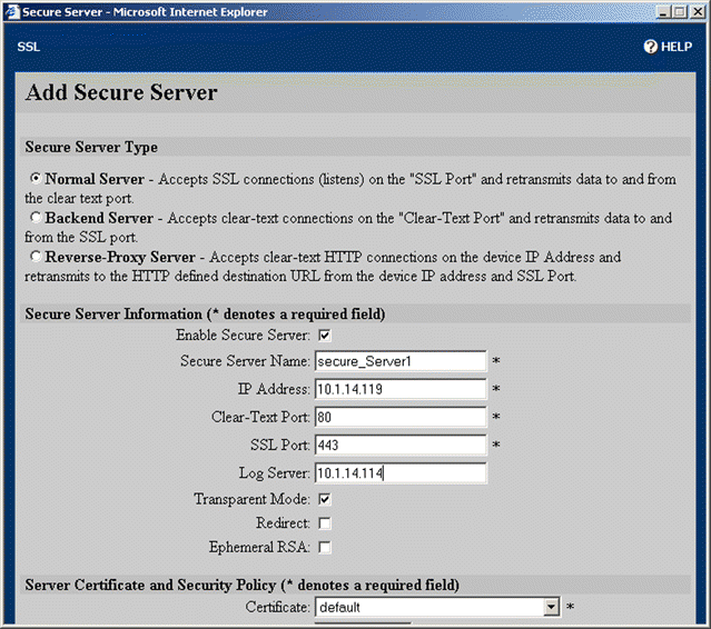
18. Choose the type of secure server to create by clicking the appropriate option button. (This example configures a Normal Server.) Type the server name, myServer, in the Secure Server Name text box. Type the IP address of the server to which to send decrypted SSL traffic in the IP Address text box. Change the Clear-Text Port to "81".
19. Scroll to the Server Certificate and Security Policy panel. Select myCert from the Certificate list box. Select myKey from the Private Key list box. Select strong from the Security Policy list box. These options are shown in Figure 5-29.

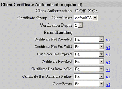
20. Select the desired options in the Client Certificate Authentication panel, shown in Figure 5-30.
21. Set up Secure URL Rewrite for the server, if desired. Enter the domain name (including wildcard, if appropriate) in the URL Clear-Text Port text box. Edit the port definitions, if necessary. Click Add, as shown in Figure 5-31, to define the URL rewrite rule.

 |
Note For more information, see the "E xample: Configuring Secure URL Rewrite" section 4-17 |
22. Click OK to create the secure server on the Secure Content Accelerator.
The same procedures are used to create and edit backend servers and reverse-proxy servers. Options presented in the window change, depending upon the type of server being configured.
This example demonstrates how to select certificates already loaded in the Secure Content Accelerator to create a certificate group. Alternatively, a PKCS#7 certificate group can be imported directly. See " Example: Importing a PKCS#7 Certificate Group", below, for a demonstration.
1. Click SSL to activate the SSL tabs.
2. Click the Certificate Groups tab. The Certificate Groups page is shown in Figure 5-32.
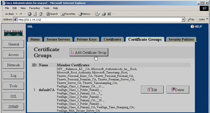
3. Click Add Certificate Group. The Add Certificate Group window opens, as shown in Figure 5-33.
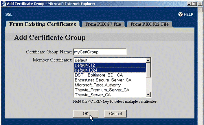
4. Type the name for the group in the Certificate Group Name text box.
5. Click and CTRL+click the certificates listed in the Member Certificates list box to add to the certificate group. You can also click and SHIFT+click either end of a contiguous group of certificates to select all certificates in it.
6. Click OK to add the certificate group to the device.
Follow the steps below to assign the certificate group to a secure server.
1. Click SSL to activate the SSL tabs.
2. Click the Secure Servers tab.
3. Either click Edit next to an existing secure server, or click Add Secure Server to create a new server. The appropriate secure server window opens.
4. Locate the Server Certificate and Security Policy panel.
5. Select "myCertGroup" from the Certificate Group - Server Chain list box. These options are shown in Figure 5-34.
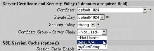
6. Click OK to add the new configuration.
 |
Note If you are creating a new secure server, you must complete configuring the server as presented previously in this chapter. |
1. Click the Secure Servers tab.
2. Click Add Secure Server. The Add Secure Server window opens.
3. Type the server name, mySecureMail, in the Secure Server Name text box. Type the IP address of the server to which to send decrypted SSL traffic. Type "110" in the Remote Port text box. Type "995" in the SSL Port text box. Select strong from the Security Policy list box. Select default-1024 from the Certificate list box. Select default-1024 from the Private Key list box. These options are shown in Figure 5-35.
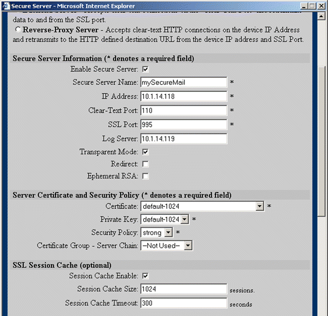
4. Click OK to create the secure server in the Secure Content Accelerator.
This example demonstrates how to generate an RSA private key named myOwnKey.
1. Click SSL to activate the SSL tabs.
2. Click Add Private Key. The Add Private Key window opens.
3. Click the Generate tab. The Generate an RSA Private Key window opens, as shown in Figure 5-36.
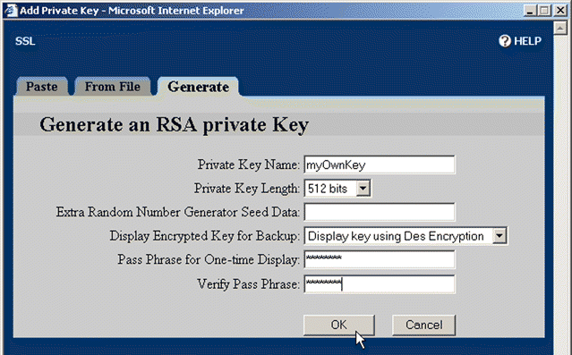
4. Type "myOwnKey" in the Private Key Name text box.
5. Select 512 bits from the Private Key Length list box. This value is proportionate to the strength of the key.
6. If you want to specify any additional seed data for the random number generator, type it into the Extra Random Number Generator Seed Data text box.
7. Choose an option in the Display Encrypted Key for Backup list box.
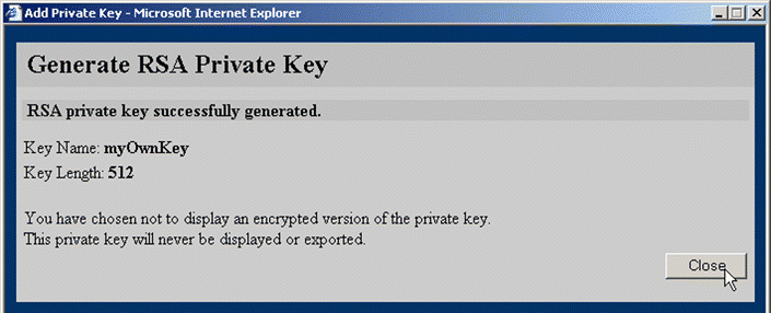
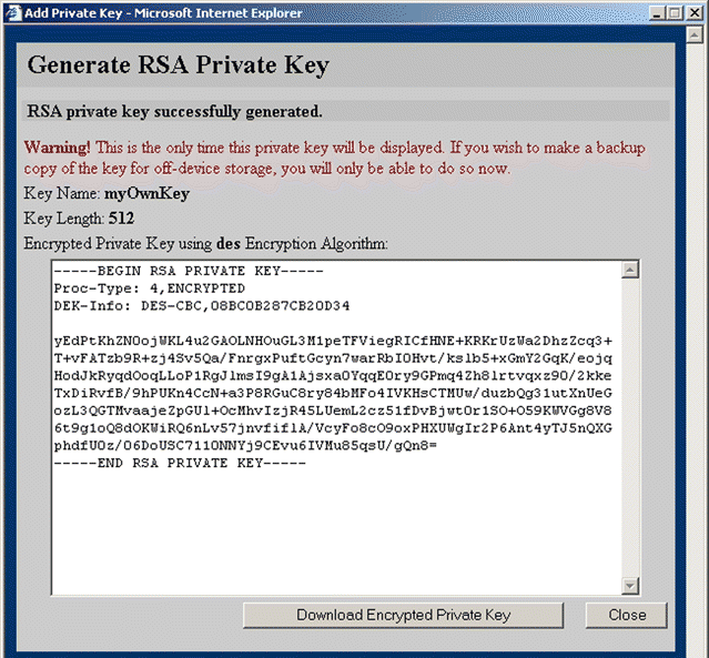
8. Click OK. Depending upon the selection made from the Display Encrypted Key for Backup list box, one of two windows opens:
1. Click SSL to activate the SSL tabs.
2. Click the Certificates tab.
3. Click Add Certificate. The Add Certificate window opens.
4. Click the Generate CSR/Self-signed Certificate tab. The Generate CSR/Self-signed Certificate page opens, as shown in Figure 5-39.
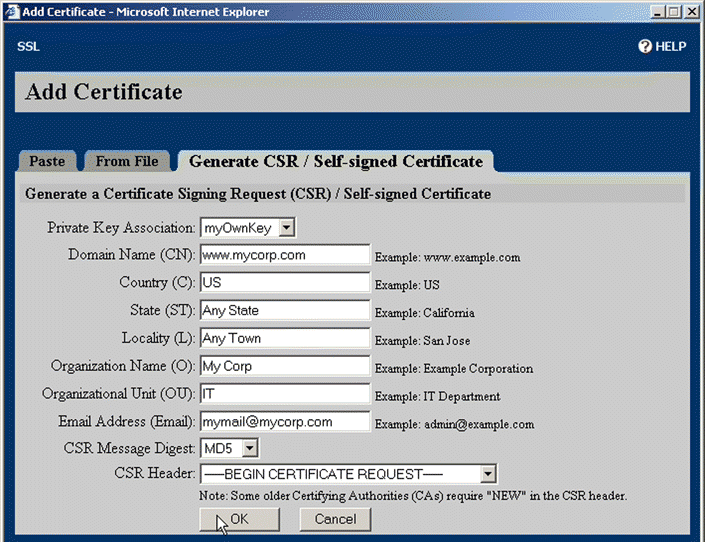
5. Select the key to associate with the certificate from the Private Key Association list box.
6. Enter the desired domain name, country, state, locality, organization name, organization unit, and e-mail address in the appropriate text boxes.
7. Select the appropriate message digest format for the signing request from the CSR Message Digest list box.
8. Select the appropriate header from the CSR Header list box.
9. Click OK. The certificate is created and the Generate Certificate Signing Request (CSR) opens, as shown in Figure 5-40.
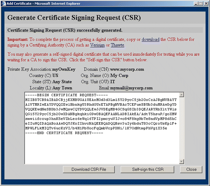
10. Click Download CSR File to save the file to the local file system for transfer to the Certificate Authority.
 |
Note If you know the preferred file name convention of the CA, name the file appropriately now. Otherwise, accept the default naming convention and rename the file later if necessary. |
11. Click Self-sign this CSR to generate a self-signed digital certificate to be used for testing while you wait for the certificate to be signed. The Generate Self-signed Certificate window opens, as shown in Figure 5-41.
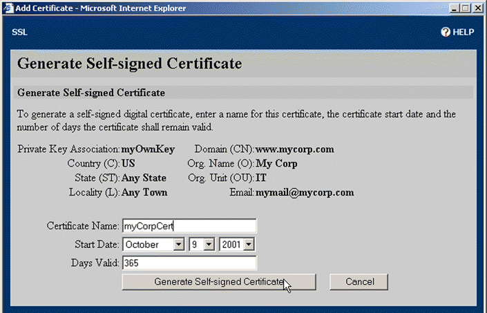
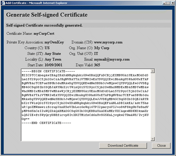
12. Type the name for the certificate in the Certificate Name text box. Select the appropriate date to begin validity of the certificate from the Start Date list boxes. Change the number of days the certificate is valid in the Days Valid text box, if desired. Click Generate Self-signed Certificate. The certificate is generated, and a window opens, allowing the certificate to be downloaded. The Generate Self-signed Certificate window is shown in Figure 5-42. Click Close.
1. Click SSL to activate the SSL tabs.
2. Click the Certificate Groups tab.
3. Click Add Certificate Group. The Add Certificate Group window opens.
4. Click the From PKCS7 File tab. The Import PKCS7 File page opens, as shown in Figure 5-43.
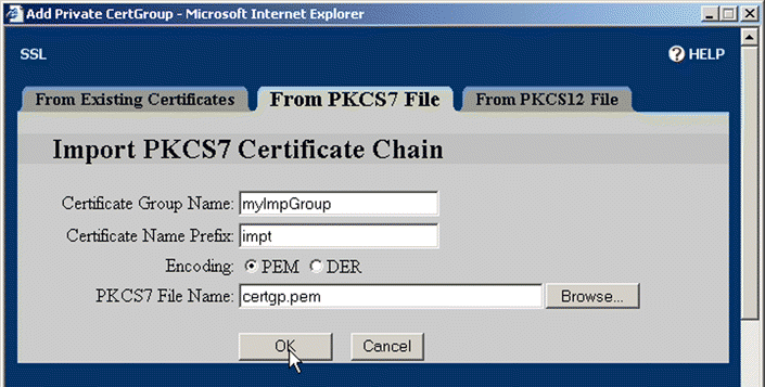
5. Type the name of the group in the Certificate Group Name text box.
6. Type the base name of the certificate in the Certificate Name Prefix text box.
7. Select the encoding option for the file to import by clicking the appropriate Encoding option button.
8. Either type the name and path of the PKCS#7 file to import, or click Browse and navigate to and select the file.
9. Click OK.
1. Click SSL to activate the SSL tabs.
2. Click the Certificate Groups tab.
3. Click Add Certificate Group. The Add Certificate Group window opens.
4. Click the From PKCS12 File tab. The Import PKCS12 Certificate Chain window opens, as shown in Figure 5-44.
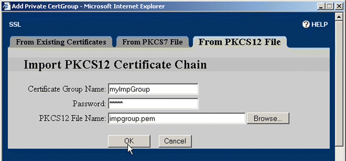
5. Type the name of the group in the Certificate Group Name text box.
6. Type the key password in the Password text box.
7. Either type the name and path of the PKCS#12 file to import, or click Browse and navigate to and select the file.
8. Click OK.
1. Click SSL to activate the SSL tabs.
2. Click Secure Server Wizard. The first screen of the wizard opens, as shown in Figure 5-45.
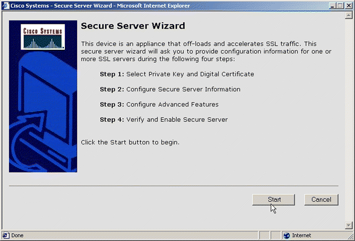
3. Follow the instructions and prompts in the wizard to configure the secure server. When you have completed configuring the server, you can immediately configure another one or exit the Secure Server wizard.
![]()
![]()
![]()
![]()
![]()
![]()
![]()
![]()
Posted: Wed Aug 21 02:46:42 PDT 2002
All contents are Copyright © 1992--2002 Cisco Systems, Inc. All rights reserved.
Important Notices and Privacy Statement.