|
|

Table Of Contents
Start Here: Check All Card Connectors!
Check Pins, Dividers, and Holes
Install the Front and Back Cards
Cutouts in the EMI Gasket for MGX Service Modules
Start Here: Check All Card Connectors!
Revised: July 25, 2006Remove Protective Cover
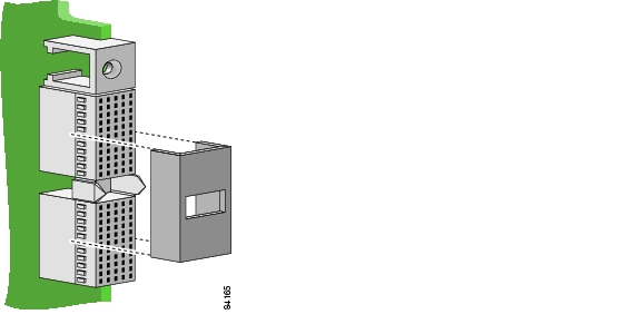
Remove the small protective cover from the rear edge of the card(s). This cover protects alignment tabs during shipping.
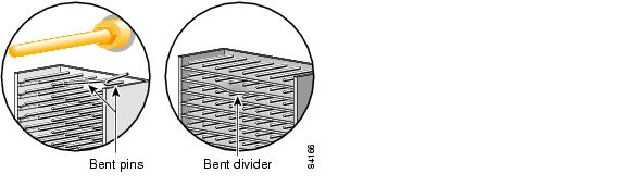
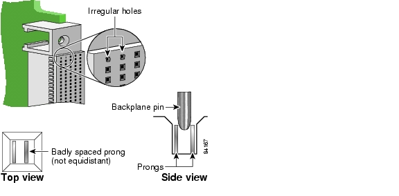
Check Pins, Dividers, and Holes
Cisco equipment is 100% inspected at the factory, but to ensure successful installation, please look at the connectors before you install a card.
If you see any of the problems shown, contact the Cisco Technical Assistance Center at 800-553-2447, 408-526-7209, or email tac@cisco.com.
CautionTo prevent damage to the backplane, do not install cards with bent pins or bent pin dividers. Do not force pins into a connector with irregular or obstructed holes. Do not insert pins into holes that contain off-center pin insertion prongs.
Install the Front and Back Cards
Card Placement
The following switch slots are reserved:
•
•
•
•
•
Caution
Refer to the hardware installation guide for your switch for more details about switch and card installation.
How to Install a Front Card
Step 1
Step 2
Step 3
Caution
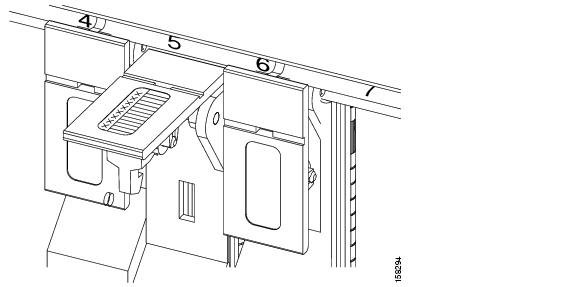
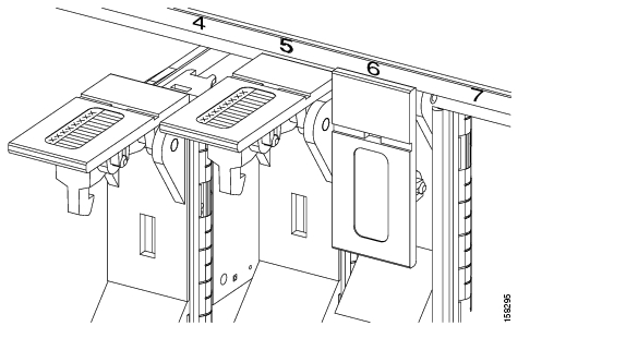
Figure 1 Correct Installation of Multiple Front Cards into a Chassis
Caution
Figure 2 Incorrect Installation of Multiple Front Cards into a Chassis
How to Install a Back Card
Caution
Step 1
Step 2
Step 3
Step 4
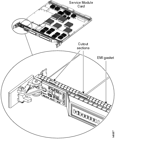
Cutouts in the EMI Gasket for MGX Service Modules
Some of the MGX Service Modules are equipped with a copper gasket to enhance EMI performance.
The gasket is mounted on the component side of the board from top to bottom behind the front faceplate. The gasket consists of a slotted copper section (which is the EMI gasket) and a stainless steel mounting track for attaching the gasket to the card.
Several MGX Service Modules have cut out sections in their EMI gasket (see illustration). These cut out sections improve board insertion and extraction.
The cut out sections are intentional and do NOT indicate that the gasket is broken or defective.
Caution
© 2006 Cisco Systems, Inc. All rights reserved.
Printed in the USA on recycled paper containing 10% postconsumer waste.
![]()
![]()
![]()
![]()
![]()
![]()
![]()
![]()
Posted: Tue Aug 15 17:51:07 PDT 2006
All contents are Copyright © 1992--2006 Cisco Systems, Inc. All rights reserved.
Important Notices and Privacy Statement.