|
|

Table Of Contents
Release Notes for Cisco MGX 8880 Software Release 5.3.00
Release 5.3.00 Features and Enhancements
Remote IP Management Connection Enhancements
Software/Firmware Compatibility Matrix
MGX and RPM Software Version Compatibility Matrix
Limitations, Restrictions, and Notes for 5.3.00
Higher Level Logical Link Limits
AXSM-E Operation, Administration, and Maintenance Cells
Command Line Interface Access Levels
AXSM Card Automatic Protection Switching Limitations
Path and Connection Trace Features
Soft Permanent Virtual Connection Interoperability
Other Limitations and Restrictions
Known MGX 8880 Media Gateway Anomalies
Known Route Processor Module Anomalies
Cisco Product Security Overview
Reporting Security Problems in Cisco Products
Obtaining Technical Assistance
Cisco Technical Support & Documentation Website
Definitions of Service Request Severity
Obtaining Additional Publications and Information
Release Notes for Cisco MGX 8880 Software Release 5.3.00
Part Number OL-8892-01 Revision B0, October 23, 2006
Table of Contents
Overview
These release notes contain the following sections:
•
"Release 5.3.00 Description" section
•
•
•
•
•
•
•
•
•
•
•
•
•
Release 5.3.00 Description
These release notes describe the system requirements, new features, and limitations that apply to Release 5.3.00 of the Cisco MGX 8880 Media Gateway, and provide Cisco support information.
For information about new VXSM features, refer to the Release Notes for the Cisco Voice Switch Service Module (VXSM), Release 5.3.00.
For information about new VISM-PR features, refer to the Release Notes for the Cisco Voice Interworking Service Module (VISM), Release 3.3.25.
Type of Release
Release 5.3.00 is a software and hardware release for the MGX 8880 media gateway.
Locating Software Updates
Release 5.3.00 software is located at:
http://www.cisco.com/kobayashi/sw-center/wan/wan-planner.shtmlnp
Route processor module (RPM) Cisco IOS software images are located at:
http://www.cisco.com/kobayashi/sw-center/sw-ios.shtml
Release 5.3.00 Features and Enhancements
This release includes the following new features for the Cisco MGX 8880 platform:
•
•
VXSM Enhancements
For information about VXSM enhancements, refer to Release Notes for the Cisco Voice Switch Service Module (VXSM), Release 5.3.00.
Security Enhancements
This release introduces the following security enhancements:
•
•
SFTP and SSH Features
Cisco MGX switches currently support the following remote access applications and protocols:
•
•
This release adds SFTP to the PXM45 card and SSH to the RPM-XF card. SFTP is an alternative to FTP that provides for secure (and authenticated) file transfer between a PXM card and a remote host.
For more information about managing Telnet and SSH features, see the following:
•
–
–
•
–
Disabling Telnet and FTP
By default, the PXM45 permits unsecured access from Telnet and FTP clients, as well as secure access from SSH and SFTP clients. A new option (16) of the cnfndparm command, along with an existing option (15), disables unsecured Telnet and FTP access from remote hosts, while permitting secure SFTP and SSH sessions.
If you plan to use SFTP and SSH on the PXM45, you should consider disabling FTP and Telnet access to improve security. Telnet and FTP transfer all user ID, password, and session management information between the client and the PXM45 using clear text. Clear, or unencrypted, text can be read by network analysis and snooping tools.
Initializing SFTP
Upgrading PXM software is not sufficient to initialize and enable the SFTP feature. You must initialize the sshd_config file and reset the MGX chassis. Because resetting a chassis can interrupt traffic, you should initialize SFTP before upgrading software so you don't need to reset it later.
To initialize SFTP, perform the following steps:
Step 1
Step 2
Step 3
Step 4
Step 5
Step 6
Note
Remote IP Management Connection Enhancements
You can manage an MGX 8850 node directly from an Ethernet or console port on the PXM, or you can configure a remote path to the PXM through a service module or route processor module. The following management paths are supported in prior releases:
•
•
Earlier releases supported intranode connections only, and you could only have one PVC between an RPM and PXM. Release 5.3.00 enhances the atm0 feature to internode connections, where an RPM on one MGX switch connects to PXMs on other MGX switches using PNNI. And now you can manage multiple PXMs from a single RPM.
Management Connection Limitations
The IP addresses of hosts accessing the MGX 8850 node are stored in a RAM cache. Because this cache has a limit of 50 entries, only 50 IP hosts can actively access the node at one time. New IP hosts are blocked until the cache clears (as result of inactivity from some hosts) to make room for new entries.
Multiple RPMs can connect to the same PXM, but each RPM can have only one connection to the PXM. This is because the PXM has a single atm0 address.
Note
Note
Configuring an RPM Management Connection
The following quick start procedure summarizes the RPM configuration procedure. This procedure assumes the RPM already has a switch partition configured for the management connection.
The following quick start procedure summarizes the PXM configuration procedure.
Example Management Configuration
This example shows how to configure a management connection between an RPM-XF on one switch and the PXM on another switch. In this example, the RPM-XF switch partition and the PXM atm0 interface are already available.
The following example configures the RPM-XF switch interface, adds a slave connection, and displays the NSAP address.
Router(config)#interface switch1.100 point-to-pointRouter(config-subif)#ip address 10.10.10.200 255.255.255.0Router(config-subif)#pvc 0/100Router(config-if-atm-vc)#ubr 1544Router(config-if-atm-vc)#switch connection vcc 0 100 master remoteRouter(config-if-swconn)#endRouter#show switch connection vcc 0 100----------------------------------------------------------Alarm state : No alarmLocal Sub-Interface : 100Local VPI : 0Local VCI : 100Remote NSAP address : defaultLocal NSAP address : 47.0091810001040000ABCD7777.000001011802.00Remote VPI : 0Remote VCI : 0The following example configures the atm0 interface of the PXM card, adds a master connection to the RPM-XF, and verifies that the connection is state is up. The NSAP address and VPI/VCI entered are the values previously displayed at the RPM-XF.
LA.8.PXM.a > ipifconfig atm0 10.10.10.144 netmask 255.255.255.0LA.8.PXM.a > svcifconfig atm0 remote 47.0091810001040000ABCD7777.000001011802.00 pvc 0.100LA.8.PXM.a > dspsvcifM8850_LA System Rev: 05.02 Apr. 25, 2006 16:36:38 PSTMGX8850 Node Alarm: NONEIP CONNECTIVITY SVC CACHE--------------------------------------------------------------------atm (unit number 0):Remote AESA: 47.0091.8100.0104.0000.abcd.7777.0000.0101.1802.00SPVC VPI.VCI: 0.100 (PCR=3642 cps)Flags: (0x6) ATMARP,LLCENCAPState: (0x1) UPRxLCN: 1505 TxLCN: 1505LCNindex: 766 LCNcallid: 0x80000001Input Frames: 1 Output Frames: 1Input Errors: 0 Output Errors: 0Input ArpReq: 0 Output ArpReq: 0Input ArpRply: 0 Output ArpRply: 0Input InArpReq: 0 Output InArpReq: 0Input InArpRply: 1 Output InArpRply: 0...Platform Enhancements
This release adds the following MGX platform enhancements.
•
The server automatically copies database tables to the new directory for a release.
•
Cisco uses this feature to upgrade hardware (Field Programmable Gate Array) FPGA images without introducing new hardware versions. This simplifies the process of adding or changing features and can reduce hardware costs for both Cisco and customers.
•
Currently, traffic sent to the MPSM-T3E3-155 and MPSM-16-T1/E1 cards is managed by the class of service only. For example, the CBR traffic class is always given priority over the VBR.RT traffic class, even if VBR.RT connections are committed and data received is within the SCR limit.
Through this QoS enhancement, the PXM QE1210 is programmed using information from the MPSM so it can manage traffic dynamically based on the committed rate of the connections and interface policy.
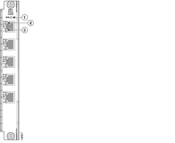
RPM-PR Ethernet Backcard
The MGX-RJ45-5-ETH is a single-height back card for the RPM-PR that provides five RJ-45 connectors for Gigabit Ethernet, Fast Ethernet, or Ethernet lines. Figure 1 shows the MGX-RJ45-5-ETH faceplate.
Figure 1 MGX-RJ45-5-ETH Back Card
AXSM-8-622-XG Service Module
The AXSM-8-622-XG Service Module is supported on the MGX 8880 in Release 5.3.00.
The Cisco° 8-Port OC-12/STM-4 Channelized/Unchannelized ATM Switch Service Module is a line card for use in the Cisco MGX° 8800 Media Gateway in combination with the Cisco PXM-45 Processor Switch Module . This ATM switch service module has eight physical 622 Mbps interfaces that can be used to deliver high-density OC-12 or STM-4 trunking/User-Network Interface (UNI) or aggregation of sub-OC-12 traffic through port channelization.
Up to 12 Cisco 8-port OC-12/STM-4 ATM switch service modules can reside in the MGX 8880 to provide support for up to 96 OC-12c/STM-4 interfaces for service providers that require both high bandwidth and high network availability.
The AXSM-8-622-XG service module is used in conjunction with the SFP-4-622 back card. This card is a 4-port SFP back card for OC-12/STM-4 interfaces.
Key Features
•
•
•
•
•
•
Release 5.2.10 Features
Maintenance Release 5.2.10 does not introduce new Cisco MGX 8880 features or enhancements.
Release 5.2.00 Features
Release 5.2.00 introduced the following hardware:
•
•
MGX-VXSM-T3 Card
Cisco MGX 8880 Release 5.2.00 introduced a third VXSM card for the support of T3 lines. The card consists of a front card with six T3 ports and a half-height back card with three T3 ports. The front card can be configured with either one back card or two back cards.
System Requirements
This section describes software compatible with Release 5.3.00, and lists the supported hardware.
Software/Firmware Compatibility Matrix
Table 1 lists Cisco WAN or Cisco IOS products that are compatible with Release 5.3.00.
MGX and RPM Software Version Compatibility Matrix
Table 2 lists the software that is compatible for use in a switch running Release 5.3.00 software.
SNMP MIB Release
The SNMP MIB release for Release 5.3.00 is mgx8XXXrel5300mib.tar.
Note
Supported Hardware
This section lists the MGX 8880 product IDs, 800 part numbers, and revision levels.
Release 5.3.00 Hardware
Release 5.3.00 introduces the following RPM-PR backcard:
•
MGX 8880 Product IDs and Card Types
Table 3 lists product IDs, minimum 800 part numbers, and the minimum revision levels for the MGX 8880.
Service Class Template Files
This section contains Service Class Template (SCT) file information for Release 5.3.00.
AXSM and AXSM/B
The AXSM and AXSM/B SCTs have the following characteristics:
•
•
•
•
The file names and checksums for the SCT files are as follows:
•
•
•
•
•
•
•
•
•
•
To confirm that the checksum of the SCT file and the file on the node match, enter dspsctchksum <filename>.
AXSM-E
The AXSM-E SCTs have the following characteristics:
•
•
•
•
•
•
The following are checksums for the new AXSM-E SCT file:
•
•
•
•
•
•
•
•
Limitations, Restrictions, and Notes for 5.3.00
This section includes information about limitations, restrictions, and notes pertaining to MGX Release 5.3.00.
•
•
When multiple VXSM cards are installed simultaneously or the configuration of multiple VXSM slots are cleared simultaneously, one or more VXSM cards could fail to be installed. This potential failure results in following recommendations (refer to CSCed12646):
–
–
Upgrading the VISM-PR Image
If you are upgrading the VISM-PR image to Release 3.2.1x or later and the PXM1E or PXM45 image from Release 4.x or earlier to Release 5.x, first upgrade the VISM-PR cards. Then, upgrade the PXM1E or PXM45 cards in the same node.
Do not configure the new VISM features until you have fully upgraded the network. After you upgrade your network to PXM1E or PXM45 Release 5.x or later and VISM-PR to Release 3.2.1x or later, apply the standard upgrade process.
Higher Level Logical Link Limits
The numbers of logical links in the higher levels of the PNNI hierarchy is limited to 30 per level when the complex node configuration is turned on. The limit is essential to reduce the processing time involved in finding the bypasses between the logical links. Each time a significant change occurs in bandwidth in one of the links within the peer group, the bypass calculation is triggered and the bypasses are usually found from one logical link to another.
If there are n logical links, the calculation involves finding n*n bypasses.
If the number of logical links n is large, a lot of processing time is used to calculate the bypasses. Limit the number of logical links per level to 30. To control the number, configure the appropriate number of aggregation tokens for the outside links for that peer group.
AXSM-32-T1E1-E Notes
The following notes apply:
•
•
•
•
•
•
•
•
•
•
•
•
•
•
–
–
•
•
•
•
•
–
–
•
AXSM-E Operation, Administration, and Maintenance Cells
The following notes apply to AXSM-E operation, administration, and maintenance (OAM) cells:
•
•
For example, if only one connection exists, that connection can receive 1,500 segment OAM loopback cells per second. If 2,000 connections exist on an AXSM-E card, and one segment OAM loopback cell per second is being channeled through on each connection, then there can only be up to 1,500 connections to receive loopback cells at any given second. The additional 500 connections are not received for that second.
•
Command Line Interface Access Levels
The following notes pertain to configuring command access levels:
•
•
•
•
•
•
Disk Space Maintenance
Because the firmware does not audit the disk space usage nor remove unused files, the disk space in C: and E: drives must be manually monitored.
Manually delete any unused saved configuration files, core files and firmware files, and the configuration files of the MGX-RPM-PR-512 and MGX-RPM-XF-512 cards to avoid a shortage of disk space required to store event logs: configuration upload files in the C: drive and the configuration of MGX-RPM-PR-512 and MGX-RPM-XF-512 cards in the E: drive.
The following steps are recommended to remove files on the system from the active controller card:
Step 1
CLI cc <directory_name>Step 2
CLI llStep 3
CLI rm <complete_filename>Step 4
CLI llSaving Configurations
The system keeps only the two most recent copies of the saved system configuration under the C:/CNF directory. You can use FTP to transfer all of the saved configurations under C:/CNF to their local server for future reference. All files under C:/CNF are not replicated over to the standby controller card under any circumstances.
Using the clrsmcnf Command
These notes pertain to the clrsmcnf command:
•
•
•
•
•
•
AXSM Card Automatic Protection Switching Limitations
These notes pertain to the Automatic Protection Switching (APS) feature:
•
•
•
•
Path and Connection Trace Features
These notes pertain to the path and connection trace features:
•
•
•
•
Priority Routing Feature
These notes pertain to the priority routing feature:
Prioritized reroute of soft permanent virtual connection (SPVCs) is not guaranteed if the SPVCs originate on a signaling port. SPVCs might get routed out of order. In-order routing of SPVCs is guaranteed on non-signaling ports.
•
•
•
–
–
–
Soft Permanent Virtual Connection Interoperability
These notes pertain to SPVC interoperability:
•
•
•
•
•
•
•
•
•
–
–
–
Manual Clocking
When resetcd is invoked, the primary and secondary (if configured) clock sources are recommitted. However, the clock to which the node is latched is not requalified. Only the backup clock is qualified if present. Recommitted means that the primary and secondary are requalified, and the node temporarily latches onto the internal oscillator. After the clock is requalified, the node locks onto the primary clock source once again.
Enabling Priority Bumping
When you enable priority bumping on the node, you cannot change the booking factor for AXSM signaling ports. You can change the booking factor for non-signaling ports.
Other Limitations and Restrictions
Other limitations and restrictions are as follows:
•
•
•
–
–
•
•
Clearing the Configuration on Redundant PXM45 Card
These notes apply to redundant cards.
•
•
Known MGX 8880 Media Gateway Anomalies
For information about anomalies in MGX Release 5.3.00 on other platforms, refer to the Release Notes for Cisco MGX 8850 (PXM1E/PXM45), Cisco MGX 8950, and Cisco MGX 8830 Switches, Release 5.3.00.
For information about anomalies with the VXSM card, refer to Release Notes for the Cisco Voice Switch Service Module (VXSM), Release 5.3.00.
For information about anomalies with the VISM card, refer to Release Notes for the Cisco Voice Interworking Service Module (VISM), Release 3.3.25.
Known Route Processor Module Anomalies
For information about anomalies with the MGX-RPM-XF-512 card, refer to Release Notes for Cisco MGX Route Processor Module (RPM-XF) IOS Release 12.4(6)T1 for PXM45-based Switches, Release 5.3.00.
For information about anomalies with the MGX-RPM-PR-512 card, refer to Release Notes for Cisco MGX Route Processor Module (RPM-PR) IOS Release 12.4(6)T1 for MGX Releases 1.3.14 and 5.3.00.
Documentation
A Guide to Cisco Multiservice Switch Documentation ships with your product. That guide contains general information about how to locate Cisco MGX, broadband and packet exchange (BPX), service expansion shelf (SES), and CWM documentation online.
Obtaining Documentation
Cisco documentation and additional literature are available on Cisco.com. Cisco also provides several ways to obtain technical assistance and other technical resources. These sections explain how to obtain technical information from Cisco Systems.
Cisco.com
You can access the most current Cisco documentation at this URL:
http://www.cisco.com/techsupport
You can access the Cisco website at this URL:
You can access international Cisco websites at this URL:
http://www.cisco.com/public/countries_languages.shtml
Product Documentation DVD
The Product Documentation DVD is a comprehensive library of technical product documentation on a portable medium. The DVD enables you to access multiple versions of installation, configuration, and command guides for Cisco hardware and software products. With the DVD, you have access to the same HTML documentation that is found on the Cisco website without being connected to the Internet. Certain products also have .PDF versions of the documentation available.
The Product Documentation DVD is available as a single unit or as a subscription. Registered Cisco.com users (Cisco direct customers) can order a Product Documentation DVD (product number DOC-DOCDVD= or DOC-DOCDVD=SUB) from Cisco Marketplace at this URL:
http://www.cisco.com/go/marketplace/
Ordering Documentation
Registered Cisco.com users may order Cisco documentation at the Product Documentation Store in the Cisco Marketplace at this URL:
http://www.cisco.com/go/marketplace/
Nonregistered Cisco.com users can order technical documentation from 8:00 a.m. to 5:00 p.m. (0800 to 1700) PDT by calling 1 866 463-3487 in the United States and Canada, or elsewhere by calling 011 408 519-5055. You can also order documentation by e-mail at tech-doc-store-mkpl@external.cisco.com or by fax at 1 408 519-5001 in the United States and Canada, or elsewhere at 011 408 519-5001.
Documentation Feedback
You can rate and provide feedback about Cisco technical documents by completing the online feedback form that appears with the technical documents on Cisco.com.
You can submit comments about Cisco documentation by using the response card (if present) behind the front cover of your document or by writing to the following address:
Cisco Systems
Attn: Customer Document Ordering
170 West Tasman Drive
San Jose, CA 95134-9883We appreciate your comments.
Cisco Product Security Overview
Cisco provides a free online Security Vulnerability Policy portal at this URL:
http://www.cisco.com/en/US/products/products_security_vulnerability_policy.html
From this site, you will find information about how to:
•
•
•
A current list of security advisories, security notices, and security responses for Cisco products is available at this URL:
To see security advisories, security notices, and security responses as they are updated in real time, you can subscribe to the Product Security Incident Response Team Really Simple Syndication (PSIRT RSS) feed. Information about how to subscribe to the PSIRT RSS feed is found at this URL:
http://www.cisco.com/en/US/products/products_psirt_rss_feed.html
Reporting Security Problems in Cisco Products
Cisco is committed to delivering secure products. We test our products internally before we release them, and we strive to correct all vulnerabilities quickly. If you think that you have identified a vulnerability in a Cisco product, contact PSIRT:
•
An emergency is either a condition in which a system is under active attack or a condition for which a severe and urgent security vulnerability should be reported. All other conditions are considered nonemergencies.
•
In an emergency, you can also reach PSIRT by telephone:
•
•
Tip
Never use a revoked or an expired encryption key. The correct public key to use in your correspondence with PSIRT is the one linked in the Contact Summary section of the Security Vulnerability Policy page at this URL:
http://www.cisco.com/en/US/products/products_security_vulnerability_policy.html
The link on this page has the current PGP key ID in use.
If you do not have or use PGP, contact PSIRT at the aforementioned e-mail addresses or phone numbers before sending any sensitive material to find other means of encrypting the data.
Obtaining Technical Assistance
Cisco Technical Support provides 24-hour-a-day award-winning technical assistance. The Cisco Technical Support & Documentation website on Cisco.com features extensive online support resources. In addition, if you have a valid Cisco service contract, Cisco Technical Assistance Center (TAC) engineers provide telephone support. If you do not have a valid Cisco service contract, contact your reseller.
Cisco Technical Support & Documentation Website
The Cisco Technical Support & Documentation website provides online documents and tools for troubleshooting and resolving technical issues with Cisco products and technologies. The website is available 24 hours a day, at this URL:
http://www.cisco.com/techsupport
Access to all tools on the Cisco Technical Support & Documentation website requires a Cisco.com user ID and password. If you have a valid service contract but do not have a user ID or password, you can register at this URL:
http://tools.cisco.com/RPF/register/register.do
Note
Submitting a Service Request
Using the online TAC Service Request Tool is the fastest way to open S3 and S4 service requests. (S3 and S4 service requests are those in which your network is minimally impaired or for which you require product information.) After you describe your situation, the TAC Service Request Tool provides recommended solutions. If your issue is not resolved using the recommended resources, your service request is assigned to a Cisco engineer. The TAC Service Request Tool is located at this URL:
http://www.cisco.com/techsupport/servicerequest
For S1 or S2 service requests, or if you do not have Internet access, contact the Cisco TAC by telephone. (S1 or S2 service requests are those in which your production network is down or severely degraded.) Cisco engineers are assigned immediately to S1 and S2 service requests to help keep your business operations running smoothly.
To open a service request by telephone, use one of the following numbers:
Asia-Pacific: +61 2 8446 7411 (Australia: 1 800 805 227)
EMEA: +32 2 704 55 55
USA: 1 800 553-2447For a complete list of Cisco TAC contacts, go to this URL:
http://www.cisco.com/techsupport/contacts
Definitions of Service Request Severity
To ensure that all service requests are reported in a standard format, Cisco has established severity definitions.
Severity 1 (S1)—An existing network is down, or there is a critical impact to your business operations. You and Cisco will commit all necessary resources around the clock to resolve the situation.
Severity 2 (S2)—Operation of an existing network is severely degraded, or significant aspects of your business operations are negatively affected by inadequate performance of Cisco products. You and Cisco will commit full-time resources during normal business hours to resolve the situation.
Severity 3 (S3)—Operational performance of the network is impaired, while most business operations remain functional. You and Cisco will commit resources during normal business hours to restore service to satisfactory levels.
Severity 4 (S4)—You require information or assistance with Cisco product capabilities, installation, or configuration. There is little or no effect on your business operations.
Obtaining Additional Publications and Information
Information about Cisco products, technologies, and network solutions is available from various online and printed sources.
•
•
http://www.cisco.com/go/marketplace/
•
•
•
http://www.cisco.com/go/iqmagazine
or view the digital edition at this URL:
http://ciscoiq.texterity.com/ciscoiq/sample/
•
•
http://www.cisco.com/en/US/products/index.html
•
http://www.cisco.com/discuss/networking
•
http://www.cisco.com/en/US/learning/index.html
Acronyms
Table 4 lists acronyms that have been referenced in these release notes.
.
CCSP, CCVP, the Cisco Square Bridge logo, Follow Me Browsing, and StackWise are trademarks of Cisco Systems, Inc.; Changing the Way We Work, Live, Play, and Learn, and iQuick Study are service marks of Cisco Systems, Inc.; and Access Registrar, Aironet, BPX, Catalyst, CCDA, CCDP, CCIE, CCIP, CCNA, CCNP, Cisco, the Cisco Certified Internetwork Expert logo, Cisco IOS, Cisco Press, Cisco Systems, Cisco Systems Capital, the Cisco Systems logo, Cisco Unity, Enterprise/Solver, EtherChannel, EtherFast, EtherSwitch, Fast Step, FormShare, GigaDrive, GigaStack, HomeLink, Internet Quotient, IOS, IP/TV, iQ Expertise, the iQ logo, iQ Net Readiness Scorecard, LightStream, Linksys, MeetingPlace, MGX, the Networkers logo, Networking Academy, Network Registrar, Packet, PIX, Post-Routing, Pre-Routing, ProConnect, RateMUX, ScriptShare, SlideCast, SMARTnet, The Fastest Way to Increase Your Internet Quotient, and TransPath are registered trademarks of Cisco Systems, Inc. and/or its affiliates in the United States and certain other countries.
All other trademarks mentioned in this document or Website are the property of their respective owners. The use of the word partner does not imply a partnership relationship between Cisco and any other company. (0601R)
Any Internet Protocol (IP) addresses used in this document are not intended to be actual addresses. Any examples, command display output, and figures included in the document are shown for illustrative purposes only. Any use of actual IP addresses in illustrative content is unintentional and coincidental.
© 2006 Cisco Systems, Inc. All rights reserved.
![]()
![]()
![]()
![]()
![]()
![]()
![]()
![]()
Posted: Thu May 24 10:08:50 PDT 2007
All contents are Copyright © 1992--2007 Cisco Systems, Inc. All rights reserved.
Important Notices and Privacy Statement.