|
|

The shelf is designed for center mounting only. It is NEBS compliant with the GR-63-CORE and GR-1089-CORE requirements.

This section describes the types of physical interfaces supported by the MGX 8240.
Table 2-1 lists the switch physical interfaces under different conditions.
| Physical Interface | Number of Ports Supported | ||
|---|---|---|---|
| No Redundancy | 1 for 4 Redundancy Support | Each PSM Blade | |
DS3 Access Port | 45 | 36 | 3 |
DS1 ports under DS3 | 1,260 | 1,008 | 84 |
DS0 ports under DS3 | 30,240 | 24,192 | 2,016 |
SONET ATM Trunk Ports | 15 (30 with APS) | 12 (24 with APS) | 1 (2 with APS) |
RS232 Serial Ports for CLI. | 16 | 16 | 1 |
10/100BaseT Ethernet Ports for network management |
|
| 1 |
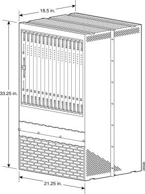
Table 2-2 shows the dimensions of an unmounted MGX 8240 unit.
| Dimension | Value |
|---|---|
Depth (without cable management) | 18.5 in. 22.5 in. |
Depth (withcable management) | |
Width (without mounting brackets) | 21.25 in. |
Height | 33.25 in.(19 RU) |
Weight (empty) | 100 lbs. |
Weight (fully loaded) | 220 lbs. |
Shelf wattage (fully loaded) | 1500 Watts |

The shelf is designed to be center-mounted in a standard telecom 23-inch relay rack. Two chassis can be mounted in a standard 7-foot configuration. There should be at least 5" betweenthe two chassis.
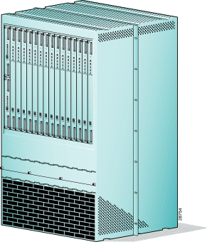
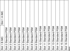
The MGX 8240 shelf has a 16-slot card cage. There are 15 full-size slots and 2 half-size slots. The two half-sized slots are for IMCs.
An MGX 8240 with IMC redundancy uses two IMCs, one primary and one backup. An IMC fits into each of the two half-size slots. At installation, usually the top IMC is primary, and the bottom IMC is backup. Figure 2-3 shows the slot designation for the cards.
 |
Note If only one IMC is to be used, it should be placed in Slot 1A. |

The PSM slots are numbered 1 through 16 (from left to right) on the bottom of the card cage.
Slot 1:
Slots 2 through 16:
The Mid-plane design:
I/O Panels are installed in the rear of the chassis. Two types of I/O cards exist:
1. The PSM I/O, with two OC3 transceivers, three DS3 ports, and an RJ45 CRAFT port.
2. The IMC I/O card, with 1 Ethernet port, 1 RJ45 console port, and BITS A and BITS B ports, and a D connector for alarms.
A blank I/O panel is supplied to cover slots that do not contain one of the above cards.
The MGX 8240 incorporates three fan trays. Each fan tray:
Any two of the three fan trays are sufficient to cool a fully-loaded chassis. Each fan has a tachometer output. These nine outputs are bused to each of the 15 PSM card slots.
During configuration, the installer should configure at least one PSM card to monitor and report fan status. All other PSM cards have this feature disabled as the default.
Upon detection of any fan failure, the PSM performs the following:
 |
Note If a fan tray fails, leave it in place until a replacement unit is available. The chassis can runo n two fan trays, but when a fan tray is removed, all three fans on the tray appear to fail. This condition generates fan failure alarms. |
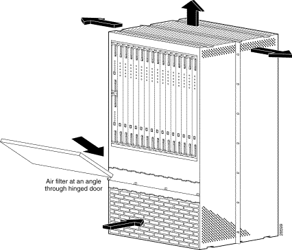
The shelf is equipped with a removable reusable air filter. Air intake is from the front and from the sides to maximize the intake air volume. Figure 2-4 represents the front and side air intakes.

The DC input module provides the following features:
A cable management system is provided with the MGX 8240. It is removable for those customers who wish to use other commercially available systems.
On the chassis, faceplates on each PSM card provide EMI protection and visual indicators as to the card's status. The PSM faceplate has LED indicators to display alarm status (see Figure 2-5).
Unused slots have blank faceplates.
All external connectivity to the PSM module is through its midplane connector. Each PSM module has its own temperature sensor for detecting over-temperature conditions, and generates an individual over-temperature major alarm.
Multiple PSM modules per chassis can be configured to back up as many as four primary PSM modules in the chassis (See "PSM Card Redundancy" section).

The LEDs indicate the following
:
The PSM I/O Modules are shown in Figure 2-6.

The PSM I/O module provides external connectivity (physical termination) on behalf of a PSM module. The PSM I/O module normally connects to the PSM module across the midplane in the same slot position. If a PSM module fails, the I/O module can be switched (controlled by the backup PSM module) to route its midplane connections to the backup PSM module. The PSM I/O module provides the following external connectors:
The Integrated Management Controller (IMC) provides centralized out-of-band management connectivity to the MGX 8240 switch. The IMC can manage (detect and reset) all PSM cards in a switch—up to 15. The IMC has the following functions:

The IMC I/O card has an RJ45 Connector for the Shelf Ethernet Interface, an RJ45 Connector for the Shelf RS232 console interface, a 15-pin connector for the 4 alarm relay contacts, and 2 BITS inputs.
The Ready LED changes from yellow to green when the IMC becomes primary, and from green to yellow when the IMC becomes secondary.
The RJ11/RS232 connector on the IMC front card is for factory use only.
![]()
![]()
![]()
![]()
![]()
![]()
![]()
![]()
Posted: Sun Sep 29 05:20:13 PDT 2002
All contents are Copyright © 1992--2002 Cisco Systems, Inc. All rights reserved.
Important Notices and Privacy Statement.