|
|

This chapter covers the following elements of installing the MGX 8240 Private Line Service Gateway:
Install the MGX 8240 in a clean, dry, well-ventilated area (see Table 1-2). Verify that a -48 VDC (approximately 40 Amps) source is close to where the MGX 8240 will be mounted. Also make sure there is an accessible site ground to connect to the equipment rack, or follow local wiring practices.
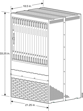
Table 1-1 shows the dimensions of an unmounted MGX 8240 unit.
| Dimension | Value |
Depth |
|
| 18.43 in |
| 22.5 in |
Width | 21.5 in |
Height | 33.25 in (19 RU) |
Weight |
|
| 100 lbs |
| 125 lbs |
| 220 lbs |
Shelf wattage (fully loaded) | 1500 watts |
The MGX 8240 should be mounted in a standard 23-inch relay rack. Two MGX 8240 systems can fit in a single rack.
Leave space in front of and behind the MGX 8240 for installation, maintenance, and wiring. You will need at least 2.5 ft (0.75 m) clearance at the front of the rack and at least 2.0 ft (0.60 m) clearance at the rear of the rack.
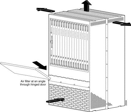
The unit vents vertically. Air is pulled in from the front and sides, and exits on the top and sides. Leave at least 5 ft between the top of the MGX 8240 and the shelf above it. The air filter fits at an angle in the lower section of the chassis (see Figure 1-3).
Certain site requirements (temperature and humidity, altitude, system grounding, and ESD/EMI precautions) must be met to ensure that the MGX 8240 unit functions well.
The MGX 8240 is intended for indoor use.Table 1-2 lists the necessary shipping, storage, and operating temperatures
| Condition | Specification |
|---|---|
Shipping temperature | -40 to +66 degrees C (-40 to +150.8 degrees F) |
Storage temperature | -30 to +50 degrees C (-22 to +122 degrees F) |
Operating temperature | 0 to 40 degrees C (32 to 104 degrees F) |
Relative humidity | 5% to 90% non-condensing Note: When the MGX 8240 is mounted with the Common Interface Module, the humidity must stay between 20% and 80%. |
Altitude | Between 60 m (200 ft) and 4000 m (13,000 ft) above sea level |
The MGX 8240 supports chassis ground (protective earth ground) for optimum performance as well as personal safety. All accessible surfaces that may become energized under a fault condition are connected to the ground.
Chassis ground points must be connected to the appropriate building ground points according to local wiring practices. Ground wires require a minimum diameter of 1.85 mm or 6 AWG (American Wire Gauge). If local codes allow grounding to the equipment rack only, ground wires are not required; use ground straps.
 |
Caution Before attempting to handle any electronic parts, put on an antistatic wrist strap (supplied) and connect it to the grounded equipment. The MGX 8240 has electro-static discharge (ESD) jacks in front and back. On the front panel, the ESD jack is at the left near the bottom of the far left PSM. On the back panel, the ESD jack is at the left near the bottom of the far left I/O Module. |
The MGX 8240 has been tested against all relevant standards of electromagnetic interference (EMI). However, Cisco recommends that users avoid placing the rack close to very strong EMI sources such as elevators, air-conditioners, photocopiers, and fax machines.
|
Caution Means reader be careful. In this situation, you might do something that could result in equipment damage or loss of data. |
 |
Warning This warning symbol means danger. You are in a situation that could cause bodily injury. Before you work on any equipment, you must be aware of the hazards involved with electrical circuitry and familiar with standard practices for preventing accidents. (To see translated versions of this warning, refer to the Regulatory Compliance and Safety Information document that accompanied the product. |
|
Warning Only trained service personnel should install the equipment. |
|
Warning Read the installation instructions before you connect the equipment to its power source. |
The MGX 8240 system is intended for installation in a RESTRICTED ACCESS LOCATION.
The guidelines that follow help ensure your safety and protect the MGX 8240 equipment. The list of guidelines may not address all potentially hazardous situations in your working environment, so be alert, and exercise good judgement at all times.
The safety guidelines are:
|
Warning Before working on a chassis or working near power supplies, unplug the power cords on an AC-powered system. On a DC-powered system, disconnect the power at the circuit breakers. |
Follow these guidelines when working on equipment powered by electricity:
|
Warning Means danger. You are in a situation that could cause bodily injury. Before you work on any equipment, be aware of the hazards involved with electrical circuitry and be familiar with standard practices for preventing accidents. |
Waarschuwing Dit waarschuwingssymbool betekent gevaar. U verkeert in een situatie die lichamelijk letsel kan veroorzaken. Voordat u aan enige apparatuur gaat werken, dient u zich bewust te zijn van de bij elektrische schakelingen betrokken risico's en dient u op de hoogte te zijn van standaard maatregelen om ongelukken te voorkomen.
Varoitus Tämä varoitusmerkki merkitsee vaaraa. Olet tilanteessa, joka voi johtaa ruumiinvammaan. Ennen kuin työskentelet minkään laitteiston parissa, ota selvää sähkökytkentöihin liittyvistä vaaroista ja tavanomaisista onnettomuuksien ehkäisykeinoista.
Attention Ce symbole d'avertissement indique un danger. Vous vous trouvez dans une situation pouvant causer des blessures ou des dommages corporels. Avant de travailler sur un équipement, soyez conscient des dangers posés par les circuits électriques et familiarisez-vous avec les procédures couramment utilisées pour éviter les accidents.
Warnung Dieses Warnsymbol bedeutet Gefahr. Sie befinden sich in einer Situation, die zu einer Körperverletzung führen könnte. Bevor Sie mit der Arbeit an irgendeinem Gerät beginnen, seien Sie sich der mit elektrischen Stromkreisen verbundenen Gefahren und der Standardpraktiken zur Vermeidung von Unfällen bewußt.
Avvertenza Questo simbolo di avvertenza indica un pericolo. La situazione potrebbe causare infortuni alle persone. Prima di lavorare su qualsiasi apparecchiatura, occorre conoscere i pericoli relativi ai circuiti elettrici ed essere al corrente delle pratiche standard per la prevenzione di incidenti.
Advarsel Dette varselsymbolet betyr fare. Du befinner deg i en situasjon som kan føre til personskade. Før du utfører arbeid på utstyr, må du vare oppmerksom på de faremomentene som elektriske kretser innebærer, samt gjøre deg kjent med vanlig praksis når det gjelder å unngå ulykker.
Aviso Este símbolo de aviso indica perigo. Encontra-se numa situação que lhe poderá causar danos físicos. Antes de começar a trabalhar com qualquer equipamento, familiarize-se com os perigos relacionados com circuitos eléctricos, e com quaisquer práticas comuns que possam prevenir possíveis acidentes.
¡Atención! Este símbolo de aviso significa peligro. Existe riesgo para su integridad física. Antes de manipular cualquier equipo, considerar los riesgos que entraña la corriente eléctrica y familiarizarse con los procedimientos estándar de prevención de accidentes.
Varning! Denna varningssymbol signalerar fara. Du befinner dig i en situation som kan leda till personskada. Innan du utför arbete på någon utrustning måste du vara medveten om farorna med elkretsar och känna till vanligt förfarande för att förebygga skador.
|
Warning Ultimate disposal of this product should be handled according to all national laws and regulations. |
Waarschuwing Dit produkt dient volgens alle landelijke wetten en voorschriften te worden afgedankt.
Varoitus Tämän tuotteen lopullisesta hävittämisestä tulee huolehtia kaikkia valtakunnallisia lakeja ja säännöksiä noudattaen.
Attention La mise au rebut définitive de ce produit doit être effectuée conformément à toutes les lois et réglementations en vigueur.
Warnung Dieses Produkt muß den geltenden Gesetzen und Vorschriften entsprechend entsorgt werden.
Avvertenza L'eliminazione finale di questo prodotto deve essere eseguita osservando le normative italiane vigenti in materia.
Advarsel Endelig disponering av dette produktet må skje i henhold til nasjonale lover og forskrifter.
Aviso A descartagem final deste produto deverá ser efectuada de acordo com os regulamentos e a legislação nacional.
¡Advertencia! El desecho final de este producto debe realizarse según todas las leyes y regulaciones nacionales.
Varning! Slutlig kassering av denna produkt bör skötas i enlighet med landets alla lagar och föreskrifter.
|
Warning Do not work on the system or connect or disconnect cables during periods of lightning activity. |
Waarschuwing Tijdens onweer dat gepaard gaat met bliksem, dient u niet aan het systeem te werken of kabels aan te sluiten of te ontkoppelen.
Varoitus Älä työskentele järjestelmän parissa äläkä yhdistä tai irrota kaapeleita ukkosilmalla.
Attention Ne pas travailler sur le système ni brancher ou débrancher les câbles pendant un orage.
Warnung Arbeiten Sie nicht am System und schließen Sie keine Kabel an bzw. trennen Sie keine ab, wenn es gewittert.
Avvertenza Non lavorare sul sistema o collegare oppure scollegare i cavi durante un temporale con fulmini.
Advarsel Utfør aldri arbeid på systemet, eller koble kabler til eller fra systemet når det tordner eller lyner.
Aviso Não trabalhe no sistema ou ligue e desligue cabos durante períodos de mau tempo (trovoada).
¡Advertencia! No operar el sistema ni conectar o desconectar cables durante el transcurso de descargas eléctricas en la atmósfera.
Varning! Vid åska skall du aldrig utföra arbete på systemet eller ansluta eller koppla loss kablar.
|
Warning Before working on equipment that is connected to power lines, remove jewelry (including rings, necklaces, and watches). Metal objects will heat up when connected to power and ground and can cause serious burns or weld the metal object to the terminals. |
Waarschuwing Alvorens aan apparatuur te werken die met elektrische leidingen is verbonden, sieraden (inclusief ringen, kettingen en horloges) verwijderen. Metalen voorwerpen worden warm wanneer ze met stroom en aarde zijn verbonden, en kunnen ernstige brandwonden veroorzaken of het metalen voorwerp aan de aansluitklemmen lassen.
Varoitus Ennen kuin työskentelet voimavirtajohtoihin kytkettyjen laitteiden parissa, ota pois kaikki korut (sormukset, kaulakorut ja kellot mukaan lukien). Metalliesineet kuumenevat, kun ne ovat yhteydessä sähkövirran ja maan kanssa, ja ne voivat aiheuttaa vakavia palovammoja tai hitsata metalliesineet kiinni liitäntänapoihin.
Attention Avant d'accéder à cet équipement connecté aux lignes électriques, ôter tout bijou (anneaux, colliers et montres compris). Lorsqu'ils sont branchés à l'alimentation et reliés à la terre, les objets métalliques chauffent, ce qui peut provoquer des blessures graves ou souder l'objet métallique aux bornes.
Warnung Vor der Arbeit an Geräten, die an das Netz angeschlossen sind, jeglichen Schmuck (einschließlich Ringe, Ketten und Uhren) abnehmen. Metallgegenstände erhitzen sich, wenn sie an das Netz und die Erde angeschlossen werden, und können schwere Verbrennungen verursachen oder an die Anschlußklemmen angeschweißt werden.
Avvertenza Prima di intervenire su apparecchiature collegate alle linee di alimentazione, togliersi qualsiasi monile (inclusi anelli, collane, braccialetti ed orologi). Gli oggetti metallici si riscaldano quando sono collegati tra punti di alimentazione e massa: possono causare ustioni gravi oppure il metallo può saldarsi ai terminali.
Advarsel Fjern alle smykker (inkludert ringer, halskjeder og klokker) før du skal arbeide på utstyr som er koblet til kraftledninger. Metallgjenstander som er koblet til kraftledninger og jord blir svært varme og kan forårsake alvorlige brannskader eller smelte fast til polene.
Aviso Antes de trabalhar em equipamento que esteja ligado a linhas de corrente, retire todas as jóias que estiver a usar (incluindo anéis, fios e relógios). Os objectos metálicos aquecerão em contacto com a corrente e em contacto com a ligação à terra, podendo causar queimaduras graves ou ficarem soldados aos terminais.
¡Advertencia! Antes de operar sobre equipos conectados a líneas de alimentación, quitarse las joyas (incluidos anillos, collares y relojes). Los objetos de metal se calientan cuando se conectan a la alimentación y a tierra, lo que puede ocasionar quemaduras graves o que los objetos metálicos queden soldados a los bornes.
Varning! Tag av alla smycken (inklusive ringar, halsband och armbandsur) innan du arbetar på utrustning som är kopplad till kraftledningar. Metallobjekt hettas upp när de kopplas ihop med ström och jord och kan förorsaka allvarliga brännskador; metallobjekt kan också sammansvetsas med kontakterna.
|
Warning Before working on a chassis or working near power supplies, unplug the power cord on AC units; disconnect the power at the circuit breaker on DC units. |
Waarschuwing Voordat u aan een frame of in de nabijheid van voedingen werkt, dient u bij wisselstroom toestellen de stekker van het netsnoer uit het stopcontact te halen; voor gelijkstroom toestellen dient u de stroom uit te schakelen bij de stroomverbreker.
Varoitus Kytke irti vaihtovirtalaitteiden virtajohto ja katkaise tasavirtalaitteiden virta suojakytkimellä, ennen kuin teet mitään asennuspohjalle tai työskentelet virtalähteiden läheisyydessä.
Attention Avant de travailler sur un châssis ou à proximité d'une alimentation électrique, débrancher le cordon d'alimentation des unités en courant alternatif ; couper l'alimentation des unités en courant continu au niveau du disjoncteur.
Warnung Bevor Sie an einem Chassis oder in der Nähe von Netzgeräten arbeiten, ziehen Sie bei Wechselstromeinheiten das Netzkabel ab bzw. schalten Sie bei Gleichstromeinheiten den Strom am Unterbrecher ab.
Avvertenza Prima di lavorare su un telaio o intorno ad alimentatori, scollegare il cavo di alimentazione sulle unità CA; scollegare l'alimentazione all'interruttore automatico sulle unità CC.
Advarsel Før det utføres arbeid på kabinettet eller det arbeides i nærheten av str¿mforsyningsenheter, skal str¿mledningen trekkes ut p vekselstrømsenheter og strømmen kobles fra ved strømbryteren på likestrømsenheter.
Aviso Antes de trabalhar num chassis, ou antes de trabalhar perto de unidades de fornecimento de energia, desligue o cabo de alimentação nas unidades de corrente alternada; desligue a corrente no disjuntor nas unidades de corrente contínua.
¡Advertencia! Antes de manipular el chasis de un equipo o trabajar cerca de una fuente de alimentación, desenchufar el cable de alimentación en los equipos de corriente alterna (CA); cortar la alimentación desde el interruptor automático en los equipos de corriente continua (CC).
Varning! Innan du arbetar med ett chassi eller nära strömförsörjningsenheter skall du för växelströmsenheter dra ur nätsladden och för likströmsenheter bryta strömmen vid överspänningsskyddet.
|
Warning Before working on a system that has an On/Off switch, turn OFF the power and unplug the power cord. |
Waarschuwing Voordat u aan een systeem werkt dat een aan/uit schakelaar heeft, dient u de stroomvoorziening UIT te schakelen en de stekker van het netsnoer uit het stopcontact te halen.
Varoitus Ennen kuin teet mitään sellaiselle järjestelmälle, jossa on kaksiasentokytkin, katkaise siitä virta ja kytke virtajohto irti.
Attention Avant de travailler sur un système équipé d'un commutateur marche-arrêt, mettre l'appareil à l'arrêt (OFF) et débrancher le cordon d'alimentation.
Warnung Bevor Sie an einem System mit Ein/Aus-Schalter arbeiten, schalten Sie das System AUS und ziehen das Netzkabel aus der Steckdose.
Avvertenza Prima di lavorare su un sistema dotato di un interruttore on/off, spegnere (OFF) il sistema e staccare il cavo dell'alimentazione.
Advarsel Slå AV strømmen og trekk ut strømledningen før det utføres arbeid på et system som er utstyrt med en av/på-bryter.
Aviso Antes de começar a trabalhar num sistema que tem um interruptor on/off, DESLIGUE a corrente eléctrica e retire o cabo de alimentação da tomada.
¡Advertencia! Antes de utilizar cualquier sistema equipado con interruptor de Encendido/Apagado (ON/OFF), cortar la alimentación y desenchufar el cable de alimentación.
Varning! Slå AV strömmen och dra ur nätsladden innan du utför arbete på ett system med strömbrytare.
|
Warning This equipment is intended to be grounded. Ensure that the host is connected to earth ground during normal use. |
Waarschuwing Deze apparatuur hoort geaard te worden Zorg dat de host-computer tijdens normaal gebruik met aarde is verbonden.
Varoitus Tämä laitteisto on tarkoitettu maadoitettavaksi. Varmista, että isäntälaite on yhdistetty maahan normaalikäytön aikana.
Attention Cet équipement doit être relié à la terre. S'assurer que l'appareil hôte est relié à la terre lors de l'utilisation normale.
Warnung Dieses Gerät muß geerdet werden. Stellen Sie sicher, daß das Host-Gerät während des normalen Betriebs an Erde gelegt ist.
Avvertenza Questa apparecchiatura deve essere collegata a massa. Accertarsi che il dispositivo host sia collegato alla massa di terra durante il normale utilizzo.
Advarsel Dette utstyret skal jordes. Forviss deg om vertsterminalen er jordet ved normalt bruk.
Aviso Este equipamento deverá estar ligado à terra. Certifique-se que o host se encontra ligado à terra durante a sua utilização normal.
¡Advertencia! Este equipo debe conectarse a tierra. Asegurarse de que el equipo principal esté conectado a tierra durante el uso normal.
Varning! Denna utrustning är avsedd att jordas. Se till att värdenheten är jordad vid normal användning.
|
Warning Read the installation instructions before you connect the system to its power source. |
Waarschuwing Raadpleeg de installatie-aanwijzingen voordat u het systeem met de voeding verbindt.
Varoitus Lue asennusohjeet ennen järjestelmän yhdistämistä virtalähteeseen.
Attention Avant de brancher le système sur la source d'alimentation, consulter les directives d'installation.
Warnung Lesen Sie die Installationsanweisungen, bevor Sie das System an die Stromquelle anschließen.
Avvertenza Consultare le istruzioni di installazione prima di collegare il sistema all'alimentatore.
Advarsel Les installasjonsinstruksjonene før systemet kobles til strømkilden.
Aviso Leia as instruções de instalação antes de ligar o sistema à sua fonte de energia.
¡Atención! Ver las instrucciones de instalación antes de conectar el sistema a la red de alimentación.
Varning! Läs installationsanvisningarna innan du kopplar systemet till dess strömförsörjningsenhet.
|
Warning Class 1 laser product. |
Waarschuwing Klasse-1 laser produkt.
Varoitus Luokan 1 lasertuote.
Attention Produit laser de classe 1.
Warnung Laserprodukt der Klasse 1.
Avvertenza Prodotto laser di Classe 1.
Advarsel Laserprodukt av klasse 1.
Aviso Produto laser de classe 1.
¡Advertencia! Producto láser Clase I.
Varning! Laserprodukt av klass 1.
|
Warning Do not stare into the beam or view it directly with optical instruments. |
Waarschuwing Niet in de straal staren of hem rechtstreeks bekijken met optische instrumenten.
Varoitus Älä katso säteeseen äläkä tarkastele sitä suoraan optisen laitteen avulla.
Attention Ne pas fixer le faisceau des yeux, ni l'observer directement à l'aide d'instruments optiques.
Warnung Nicht direkt in den Strahl blicken und ihn nicht direkt mit optischen Geräten prüfen.
Avvertenza Non fissare il raggio con gli occhi né usare strumenti ottici per osservarlo direttamente.
Advarsel Stirr eller se ikke direkte p strlen med optiske instrumenter.
Aviso Não olhe fixamente para o raio, nem olhe para ele directamente com instrumentos ópticos.
¡Advertencia! No mirar fijamente el haz ni observarlo directamente con instrumentos ópticos.
Varning! Rikta inte blicken in mot strålen och titta inte direkt på den genom optiska instrument.
To install the MGX 8240, you will need the following:
|
Caution An antistatic wrist strap must be worn during installation to prevent electrostatic damage to the MGX 8240. |
|
Caution Three people are needed to lift the chassis. If three people are not available, use a hand lift. |
Unpack the box(es) and check contents against the shipping list (see Appendix B). Save the packaging.
If the box has been damaged or if some parts are missing or defective, call 800-553-2447 and the package carrier to report the damage. Obtain a Returned Material Authorization (RMA) number and include the RMA number on the label. Return the unit in original packaging.
The following sections describe the procedures required to mount the MGX 8240 and bring it on line.
|
Caution Before attempting to handle electronic parts, put on a grounded antistatic wrist strap. |
Step 1 Use the bolt-positioning template provided by Cisco to plan position of bolts. You may find it helpful to install some bolts from the back to the front before lifting the chassis into place.
Position the MGX 8240 at the top of the equipment rack or otherwise as planned by engineers. Cisco recommends that installers have three people available to lift the chassis, and have a fourth person to bolt the chassis into place. If three people are not available, use a hand lift.
Step 2 Connect the chassis ground wire to the signal ground lug on the rear of the switch.
 |
Note No more than two MGX 8240s can be mounted in a 7-foot rack. |
This step is only for persons who need to retrofit the MGX 8240. If you have received the retrofit shipping kit and need to retrofit your MGX 8240 switch, use the information provided in Appendix C, "Retrofit MGX 8240 Installation Addendum."
The MGX 8240 requires -42 VDC to -56 VDC power at approximately 40 Amps for a fully loaded shelf.
|
Note Make sure power is turned off. |
Step 1 Connect the DC power (Cisco recommends number #6 AWG Solid Wire).
Step 2 The MGX 8240 supports dual DC feeds. Determine if you want two separate dual feeds or one.
Step 3 Connect one end from the DC power into the MGX 8240 connector block as shown below.
| Cable Type | Connector Type | Purpose |
|---|---|---|
Power | #6 AWG lug | Supplies -48 VDC power to the MGX 8240 |
The MGX 8240 has 15 full-size slots and 2 half-size slots. An IMC fits into each of the two half-size slots. Redundancy is optional, if you want redundancy, you may install two IMC cards (one primary and one backup).
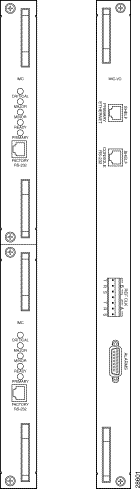
The IMC I/O Panel has an RJ45 connector for the Shelf Ethernet Interface, an RJ11 connector for the Shelf RS232 serial interface, pin connectors for the 4 alarm relay contacts, and 2 BITS inputs.
The Redundant Switch Out LED changes from yellow to green when the IMC becomes primary, and from green to yellow when the IMC becomes secondary.
The RS232 connector is for factory use only.
The Reset button, recessed about 1.5 inches behind the faceplate, does a hard reset of the card.
The IMC takes the place of the Common Interface Module (CIM). The CIMs on older chassis are being replaced with IMCs. Release 2.2 C2X MGX 8240 chassis comes with IMC card(s) installed (one is required, two are optional for redundancy).
IMC cards are hot-swappable. Replacing a CIM unit with an IMC card requires several external changes, including changing BITS clock connections and moving Ethernet and RS232 connectors from the old CEMI/O card to the new IMCI/O card. See Figure 1-6

|
Note If you are changing from a CIM to an IMC card on a chassis with traffic, you will need to refer to the IMC Upgrade Procedure, available from TAC. |
Whenever switching over to standby IMC, all the active telnet and ftp sessions need to be reinitialed. The current ftp session would get terminated with "netout: Socket operation on non-socket" error for ftp and all telnet sessions would hang.
The IMC card requires information on the following parameters:
After FDOS, users can access the IMC card through all the same means that access the PSM cards: V-CLI, VT-100, telnet, etc. However, to do FDOS, it is necessary to use the serial port, connecting to a dumb terminal or PC.
To perform FDOS on the IMC card, follow the steps below:
Step 1 In a terminal window, at the login prompt, enter the following command:
sysadminAt the password prompt, enter the following command:
sysadminStep 2 At the IMCCMDR> prompt, type <?> or help to show options.
Step 3 You will see a screen containing eight commands: change, menus, show, oper, set, exit, connect, and remoteshell. For FDOS, you will use the menu command. Enter the following command:
IMCCMDR> menu |
Note In IMCCMDR, it is not necessary to type the whole command, only the first letter(s) unique to the commands. For instance, for the menu command, you can type m. |
This first screen will have four options:
1. Node Setup
2. Administration
3. Help
4. Exit
Step 4 Node Setup will be highlighted. Press <Enter>.
Step 5 Under Node Setup you will have two options: 1. Node Config and 2. SNMP Configuration. Node Config will be highlighted. Press <Enter>.
You will see a Node Configuration screen that requires you to supply information on the following:
Step 6 When those are set, press <Shift>+<F1> to enter data.
Step 7 You will see a Node Configuration screen prompting you to update the parameters now. Use the arrow key to highlight Yes. Press <Enter>.
Step 8 You will see a screen prompting you to reboot now. Highlight Yes and press <Enter> if you can reboot safely, or No to reboot later. Note: if you reboot now, you will have to telnet back in to the CMDR in order to make more changes.
Step 9 If you choose No and do not reboot, you will see the Node Setup window again. Node Config will be highlighted. Use the arrow key to highlight SNMP Config. Press <Enter>.
Step 10 You will see two options: 1. Manager/Trap Reporting and 2. Community Information. Manager/Trap Reporting will be highlighted. Press <Enter>.
Step 11 In the Trap Report Screen, New will be highlighted. Press <Enter>. You will see the New Manager screen prompting you for the IP address of the chassis that will receive traps. Enter the IP address.
Step 12 You will see a screen prompting you to send the traps to the address. Enter Yes. Enter the port number to which traps are sent (default is 162). Indicate whether the trap community is private or public. Press <Shift>+<F1>.
Step 13 You will see the SNMP Config screen again. Use the arrow key to highlight Community Information and press <Enter>. You will see the Community String Access screen. New will be highlighted. Press <Enter>. You will see the New Community String screen. Fill in the name of the community string (such as public or private) and press <Shift>+<F1>. You will see another screen prompting you to allow GETs, SETs, and TRAPs. The default answers are all yes. Select Yes or No, and press <Shift>+<F1>.
Step 14 Press <Esc> to return to the main menu window. With the arrow keys, highlight Administration and press <Enter>. You will see a screen with two options: 1. Set System Time and 2. Operator Access. Set System Time will be highlighted. Press <Enter>.
Step 15 You will see a screen prompting you for information on the system date, time, and time zone. Set them, and press <Shift>+<F1>.
Step 16 You will return to the Administration window. If you have finished making changes and do not want to add a new user, then reboot (see directions below).
If you want to add a user, use the arrow key to highlight Operator Access. You will see a new screen, on which New will be highlighted. Press <Enter>. Use the arrow key to highlight "Add new user." You will see a screen prompting you to enter the new user's login ID, password, and security level. To see the menu of possible security levels, highlight the Display Only Access and press <Enter>. Choose security level and press <Shift>+<F1>.
Step 17 To reboot, use <Esc> to return to the Main menu. Use the arrow key to highlight the Exit option, and press <Enter>.
After FDOS, the IMC's Ready LED will turn green, signalling that NAT is possible.
The secondary IMC automatically derives FDOS configuration from the primary. The user does not have to perform FDOS on the secondary card.
To install the I/O modules on the rear of the chassis, perform the following steps:
Step 1 Put the CIMI/O into slot 1, on the far right. Slide it in until you feel a slight resistance, then put your thumbs on the thumb levers and push the module gently into place.
Step 2 Attach the remaining 15 I/O modules into their respective slots.

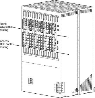
The MGX 8240 provides two types of network connections (refer to Table 1-4):
1. DS3 Channelized Access with IOM or OC3 channelized access with IOO.
2. OC3 Single-Mode Intermediate Reach fiber unchannelized for network.
The DS3 channelized access typically connects to Digital Cross-Connect Systems (DCS) or M13 multiplexers via a DSX-3 cross-connect panel. The DS3 connectors are located on each rear I/0 panel (slots 2-16).
Perform the following steps to make the connection:
Step 1 Connect the BNC on the DS3 access Tx port to the Rx of far end equipment. Use the lower cable tray.
Step 2 Connect the BNC on the Rx port to the Tx port.
Step 3 Repeat Steps 1 and 2 for each of the remaining DS3 connections.
The OC3 channelized access connects to DS3/OC3 sonet multiplexors via a fiber optics patch panel. The OC3 channelized access support bidirectional and unidirectional, non-revertive 1+1 Automatic Protection Switching (APS).
Perform the following steps to make the connection:
Step 1 Connect the top Access OC3 connector to the primary connection.
Step 2 Connect the bottom Access OC3 connector to the associated backup circuit. Use the bottom cable tray.
|
Note Figure 1-8 shows the cabling for a DS3; cabling for the OC3 differs (see Figure 1-4). |
| Cable Type | Connector Type | Purpose |
|---|---|---|
Channelized DS3 | BNC | Supply DS3 connectivity to customer equipment |
OC3 | SC | Supply OC3 connectivity to network equipment |
Channelized OC3 | SC | Supply OC3 connectivity to customer equipment |
The OC3 ATM trunk connects to ATM core switches via a fiber optics patch panel. The OC3 ATM trunks support bidirectional and unidirectional, non-revertive 1+1 Automatic Protection Switching (APS). Perform the following steps to connect the OC3 ATM trunk:
Step 1 Connect the top network OC3 connector to the primary trunk connection.
Step 2 Connect the bottom network OC3 connector to the associated backup circuit. Use the upper cable tray.
Perform the following steps to install the modules on the front of the chassis:
Step 1 Put the PSM into slot 2. Slide it forward until you feel a slight resistance, then put your thumbs on the thumb levers and push the module gently into place.
|
Warning Improper insertion of card can damage the midplane. |
Step 2 Place the remaining 14 PSMs in the same manner.
|
Note The FACTORY RS232 connector is for manufacturing purposes only—do not use it. |
The MGX 8240 is connected to the IMC IO Ethernet port.
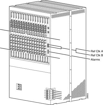
The MGX 8240 has two BITS inputs labeled Ref CLK A and Ref CLK B. Both inputs are identical; if you are installing only one BITS source, it does not matter which input you use. The connections are characterized by three wires labeled T (Tip), R (Ring), and S (Signal Ground).
The BITS Clock Source should be a DS1, B8ZS signal from Stratum 3 or higher clock source. The clock source is terminated at the unit.
|
Note Figure 1-9 shows the cabling for a DS3; cabling for the OC3 differs (see Figure 1-4). |
To start the MGX 8240, perform the following steps:
Step 1 Turn the power switch to the ON position.
Step 2 Verify that the Ready LED turns green after all connections are loaded (this may take up to ten minutes).
|
Note If the Ready LED does not turn green after ten minutes, contact Customer Support. |
On power up, the PSM starts diagnostics, including register, RAM, and control (interrupts). Where appropriate, multiple functional blocks are tested, with the use of loopback functionality. The Startup BERT Loopback test follows the hardware diagnostics.
After each sub-system has been individually tested, the data paths between sub-systems are tested. After the diagnostics are completed, the PSM loads the Operating software from flash into RAM. Then the PSM reads and processes the configuration files from the Flash. By doing so, the system configures ports and makes connections. After all the configuration files are executed, the Ready LED turns green, signalling that provisioning is finished.
The internal OAM Loopback test runs continuously. If it fails, the health monitor reboots the system.
Perform First Day of Service (FDOS) on the MGX 8240 to verify that the switch is ready to be managed by the Network Management System.
Before starting FDOS, you need the following:
Perform the following steps to make an RS232 terminal connection:
Step 1 Use the RS232 DCE RJ45 connector to connect the cable between the VT-100 terminal and MGX 8240.
Step 2 Configure terminal device for VT-100 with a baud rate of 9600 (8, N, 1).
Step 3 Configure the Ethernet Connector Signal list (RJ45 connector).
Table 1-5 and Table 1-6 show the Ethernet and RS232 connector signal lists.
| Pin No. | Signal |
|---|---|
1 | TDP (Transmit Data Positive) |
2 | TDN (Transmit Data Negative) |
3 | RDP (Receive Data Positive) |
4 | No Connect |
5 | No Connect |
6 | RDN (Receive Data Negative) |
7 | No Connect |
8 | No Connect |
| Pin No. | Signal |
|---|---|
1 | CTS (Clear to Send) |
2 | DTR (Data Terminal Ready) |
3 | TXD (Transmit Data) |
4 | Ground |
5 | Ground |
6 | RXD (Receive Data) |
7 | DSR (Data Set Ready) |
8 | RTS (Ready to Send) |
The Craft Interface/Console Management Diagnostic Resource (CMDR or Commander) is the menu-based tool available to set up FDOS. The menu-based tool is easily invoked when a user logs in through the serial port into the switch. CMDR is menu based and several menus are available.
To set up the Craft Interface/CMDR, connect your VT-100 terminal (or laptop) via the RS232c cable to the serial port on the module.
To begin FDOS, perform the following steps:
Step 1 Enter CMDR and press <Enter>.
Step 2 Enter your username and password on the Login menu (Default is ultimate/ultimate; sysadmin/sysadmin may also work).
Figure 1-10 shows the Login procedure.
Step 3 To display the menu mode, enter menu.
The Main menu displays (see Figure 1-11).

Step 4 Use the following keys to navigate through the screens:
The instructions below are to be followed only on a chassis that has the CIM. For a chassis using the IMC card, go to FDOS on PSM Cards in Chassis Using IMC.
As each card is installed, you need to set the following values:
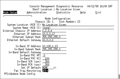
Set the node IP address by using the Node Setup menu. Perform the following steps:
Step 1 Move the cursor to Node Setup and press <Enter>. The Node Setup menu displays.
Step 2 To change the Node IP address, select Node Configuration for the Node Configuration Window (see Figure 1-12).
Step 3 Position the cursor at the System Location blank and enter the location.
Step 4 Position the cursor at the System Name blank and enter the name.
Step 5 Position the cursor at the IP address and enter the new IP address over the old one.
|
Note If you do not use the default IP address and set the subnet mask to 255.255.255.0, redundancy will not work. |
Step 6 Set the Subnet Mask to 255.255.255.0.
Step 7 Use Default Gateway as the IP address of the router to direct all external IP packets towards.
Step 8 After entering all of the above information, press <F1> to update the configuration information in memory. For this information to take effect, the node requires a reboot (this is done in Step 16).
Step 9 At the power restart, the CMDR dialog box prompts you to reboot the system. Enter No.
Step 10 To program the MGX 8240 node to send traps to the management station, perform the following steps:
(a) From the Node Setup menu, press <Enter>.
(b) Select the SNMP Configuration menu. The SNMP Configuration displays (see Figure 1-13).

Step 11 Press <Enter>. This enters the information related to the Trap manager. The Trap Report menu displays (see Fig. 1-14).

Step 12 With the cursor on New, press <Enter> again to see the New Manager submenu (see Figure 1-15).
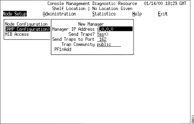
Step 13 Position the cursor on the IP address area and enter the IP address of the workstation to receive the traps.
Step 14 Select Send Traps and enter Yes. Leave all other information unchanged (Port = 162, Trap = Public).
Step 15 To make the changes effective, press <F1>. Perform a card restart to make these changes effective. After a restart, the card can be managed remotely and can receive traps using SNMP. This operation should be extended to all cards in the network.
Step 16 Exit the menu system after all configuration changes are made. The prompt changes to CMDR>>.
Step 17 Reboot the system by entering the following command:
oper rebootStep 18 You must reboot the system for all changes to take place.
|
Note Before beginning FDOS on any PSM card, you must have done FDOS on the IMC card. |
All cards in the MGX 8240 chassis can have FDOS provisioning done through the primary IMC. Users open a CMDR session for each PSM to allow FDOS provisioning.
As each card is installed, you need to set the following values:
Step 1 In a terminal window, at the login prompt, enter the following command:
sysadminStep 2 At the password prompt, enter the following command:
sysadmin |
Note In CMDR it is not necessary to type the whole command, but only the first letter(s) unique to the commands. |
Step 3 This first screen will have five options (Node Setup, Administration, Statistics, Help, Exit). Node Setup will be highlighted. Press <Enter>.
Step 4 Under Node Setup you will have two options: 1. Node Config and 2. SNMP Configuration. Node Config will be highlighted. Press <Enter>.
Step 5 You will see a Node Configuration screen that requires you to fill in information on the following:
Step 6 When those are set, press <Shift>+<F1> (or PF1 from a dumb terminal) to enter d.
Step 7 You will see a Node Configuration screen prompting you to update the parameters now. Use the arrow key to highlight Yes. Press <Enter>.
Step 8 You will see a screen that prompting you to reboot now. Highlight Yes and press <Enter>if you can reboot safely, or No to reboot later. Note: if you reboot now, you will have to press <Control>+ T to return to the IMC CMDR.
Step 9 If you choose No and do not reboot, you will see the Node Setup window again. Node Config will be highlighted. Use the arrow key to highlight SNMP Config. Press <Enter>.
Step 10 You will see two options: 1. Manager/Trap Reporting and 2. Community Information. Manager/Trap Reporting will be highlighted. Press <Enter>.
Step 11 In the Trap Report Screen, New will be highlighted. Press <Enter>. You will see the New Manager screen prompting you for the IP address of the host that will receive traps. Enter the IP address.
Step 12 You will see a New Manager screen, prompting you to send the traps to the address. Select Yes. Enter the port number to which traps are sent (default is 162). Indicate whether the trap community is private or public. Press <Shift>+<F1> (or PF1 from a dumb terminal).
Step 13 You will see the SNMP Config screen again. Use the arrow key to highlight Community Information. Press <Enter>.
Step 14 You will see the Community String Access screen. New will be highlighted. Press <Enter>. You will see the New Community String screen. Fill in the name of the community string (such as public or private). Press <Shift>+<F1> (or PF1 from a dumb terminal).
Step 15 You will see another screen that prompting you to allow GETs, SETs, and TRAPs. The default answers are all yes. Select Yes or No, and press <Shift>+<F1> (or PF1 from a dumb terminal).
Step 16 Press Esc to return to the main menu window. With the arrow keys, highlight Administration. Press <Enter>. You will see a screen with two options: 1. Set System Time and 2. Operator Access. Set System Time will be highlighted. Press <Enter>.
Step 17 You will see a screen prompting you for information on the system date, time, and time zone. Set them. Press <Shift>+<F1> (or PF1 from a dumb terminal).
Step 18 You will return to the Administration window. If you have finished making changes and do not want to add a new user, then reboot (see directions below).
Step 19 If you want to add a user, use the arrow key to highlight Operator Access. You will see a new screen, on which New will be highlighted. Press <Enter>. Use the arrow key to highlight Add new user.
Step 20 You will see a screen prompting you to enter the new user's login ID, password, and security level. To see the menu of possible security levels, highlight Display Only Access and press <Enter>. Choose security level and press <Shift>+<F1> (or PF1 from a dumb terminal).
Step 21 To reboot, press <Esc> to return to the main menu. Use the arrow key to highlight the Exit option, and press <Enter>.
Step 22 Repeat the steps above for all other PSM cards in the chassis.
![]()
![]()
![]()
![]()
![]()
![]()
![]()
![]()
Posted: Tue Oct 1 09:10:40 PDT 2002
All contents are Copyright © 1992--2002 Cisco Systems, Inc. All rights reserved.
Important Notices and Privacy Statement.